Andrzej Pożarycki and Tomasz Garbowski / Procedia Eng<strong>in</strong>eer<strong>in</strong>g 57 ( 2013 ) 922 – 928923The work [11-12] presents, that durability, re<strong>in</strong>forced pavement lifetime prediction analysis and grad<strong>in</strong>g <strong>of</strong> geosyntheticasphalt <strong>in</strong>terlayer systems can be obta<strong>in</strong>ed by fatigue crack growth test<strong>in</strong>g with the wedge splitt<strong>in</strong>g test <strong>in</strong>stead <strong>of</strong> the mostcommonly used beams and bend<strong>in</strong>g tests [13]. Based on such experiment they reported that SAMI and SAMI + asphaltre<strong>in</strong>forcement asphalt <strong>in</strong>terlayer systems outperform standard asphalt re<strong>in</strong>forcement systems (asphalt emulsion spray<strong>in</strong>g)and non-<strong>in</strong>terlayer systems by far, especially at low temperatures and high loads.Experimental data clearly evidences the beneficial, though rather qualitative, character <strong>of</strong> engaged geosynthetics. Amongmany available <strong>in</strong> the literature method <strong>of</strong> model<strong>in</strong>g the crack propagation <strong>in</strong> composite materials, the embeddeddiscont<strong>in</strong>uity, constitutive smeared crack<strong>in</strong>g [14], or X-FEM [15] seem to be frequently used by various researchers tocapture the crack growth effect. In the discrete crack propagation formulation a l<strong>in</strong>ear elastic fracture mechanics is usuallyemployed, on the other hand for the constitutive model<strong>in</strong>g <strong>of</strong> crack the damage mechanics is used. The discreet and smearedapproaches are different <strong>in</strong> nature but both require a particular set <strong>of</strong> parameter <strong>in</strong> order to properly simulate fractur<strong>in</strong>g anddegradation <strong>of</strong> material stiffness dur<strong>in</strong>g fatigue test. Unfortunately not all <strong>of</strong> the needed parameters are easily accessible.Therefore the careful choice <strong>of</strong> proper crack model<strong>in</strong>g technique has to be made based on available experimental data anddesired model<strong>in</strong>g expectations. Dur<strong>in</strong>g the fatigue test <strong>of</strong>ten more than millions <strong>of</strong> load<strong>in</strong>g cycles are generated therefore thecrack clos<strong>in</strong>g and open<strong>in</strong>g (due to cycl<strong>in</strong>g load<strong>in</strong>g) and self-heal<strong>in</strong>g <strong>of</strong> visco-elasto-plastic materials seem to be an importantphenomenon. In order to capture such behavior the proper material model which is capable to describe compressive andtensile stiffness degradation separately (e.g. [14], [16]) should be employed. By hav<strong>in</strong>g <strong>in</strong>dependent material behavior <strong>in</strong>tension and compression one can observe a recovery <strong>of</strong> progressive damage especially when material switches from tensionto compression and vice versa.However the task <strong>of</strong> pavement model<strong>in</strong>g is an example that confirms the thesis, that relatively simple eng<strong>in</strong>eer<strong>in</strong>gapproach <strong>of</strong> analysis <strong>of</strong> a layered system is a better approximation to the reality than the mathematically exact solution [17].2. Models <strong>of</strong> composites with isotropic matrix re<strong>in</strong>forced with regular gridHere the attention is given to the group <strong>of</strong> theoretical solutions, which may <strong>in</strong>clude alternative models <strong>of</strong> re<strong>in</strong>forcedconcrete pavement construction [18]. The composite material consist<strong>in</strong>g <strong>of</strong> a discrete grid embedded <strong>in</strong> the m<strong>in</strong>eral-asphaltmatrix can be further simplified through e.g. homogenization. Alternatively, if the composite is modeled as layered structure<strong>in</strong> the frame <strong>of</strong> isotropic l<strong>in</strong>ear theory <strong>of</strong> elasticity, the re<strong>in</strong>forcement can be treated as an equivalent layer with f<strong>in</strong>itethickness.2.1 Employment the elementary homogenizationSelected for analysis examples are based on geosynthetics made <strong>of</strong> glass fibers. The first is the geogrid and the other is ageocomposites, see Table 1.Table 1 Parameters <strong>of</strong> geosynthetics chosen for analysisa) GEOGRID ::GlassGrid 8550::Tensile strength:Grid elongation at break:Grid size:Young`s modulus <strong>of</strong> the glass filaments:Mass per unit area:Adhesive back<strong>in</strong>g:b) GEOCOMPOSITES ::PGM-G 100/100::Tensile strength:Grid elongation at break:Mesh width <strong>of</strong> the glass filaments:Young`s modulus <strong>of</strong> the glass filaments:Mass per unit area:Asphalt retention:Strength at 2% stra<strong>in</strong>:50 × 50 kN/m< 5%,25 × 25 mm,73 000 MPa,185 g/m2,pressure sensitive.100 × 100 kN/m,< 3%,40 × 40 mm,73 000 MPa,430 g/m 2 ,1.1 kg/m 2 ,68 × 68 kN/m.
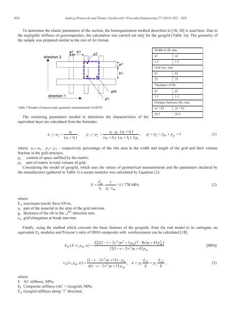
924 Andrzej Pożarycki and Tomasz Garbowski / Procedia Eng<strong>in</strong>eer<strong>in</strong>g 57 ( 2013 ) 922 – 928To determ<strong>in</strong>e the elastic parameters <strong>of</strong> the section, the homogenization method described <strong>in</strong> [18, 20] is used here. Due tothe negligible stiffness <strong>of</strong> geocomposites, the calculation was carried out only for the geogrid (Table 1a). The geometry <strong>of</strong>the sample was prepared similar to the size <strong>of</strong> A4 format.Table 2 Results <strong>of</strong> macroscopic geometry measurements GG8550The rema<strong>in</strong><strong>in</strong>g parameters needed to determ<strong>in</strong>e the characteristics <strong>of</strong> theequivalent layer are calculated from the formulas:Width <strong>of</strong> rib, mma1a21.5 1.5Grid size, mmb1b225 25Thickness <strong>of</strong> ribg1g21.5 1.5Distance between ribs, mma1 + b1 a1 + b126.5 26.5ua1= u =( a + b )1 21 1a ⋅g ⋅ ( a + b )1 1 1 1, p 1= p2=( a1+ b1) ⋅ ( a1+ b1) ⋅2g1, p1+ p2 + pm+ pp= 1(1)where: u 1= u2, p 1= p2- respectively percentage <strong>of</strong> the ribs area <strong>in</strong> the width and length <strong>of</strong> the grid and their volumefraction <strong>in</strong> the grid structure,p p content <strong>of</strong> space unfilled by the matrix,p m part <strong>of</strong> matrix <strong>in</strong> total volume <strong>of</strong> grid,Consider<strong>in</strong>g the model <strong>of</strong> geogrid, which uses the values <strong>of</strong> geometrical measurements and the parameters declared bythe manufacturer (gathered <strong>in</strong> Table 1) a secant modulus was calculated by Equation (2):Fm1E = ⋅u g ⋅εwhere:F m maximum tensile force kN/m,u i part <strong>of</strong> the material <strong>in</strong> the strip <strong>of</strong> the grid mm/mmg i thickness <strong>of</strong> the rib <strong>in</strong> the „i th ” direction mm,є m grid elongation at break mm/mm.i i m=11 778 MPa (2)F<strong>in</strong>ally, us<strong>in</strong>g the method which converts the basic features <strong>of</strong> the geogrids, from the real model to its surrogate, anequivalent E K modulus and Poisson’s ratio <strong>of</strong> HMA composite with re<strong>in</strong>forcement can be calculated [18].2 2 2mm−ν− ν2κ+ pmE[2(1 −ν−2 ν ) κ + 3 p (7 −8 ν) κ+ 45 p ]EK( E, ν, pm, κ ) =12(1 2 ) 45[MPa]where:E AC stiffness, MPa;E k Composite stiffness (AC + Geogrid), MPa;E zi Geogrid stiffness along “i” direction;2(1−ν−2 ν ) κ+ 15ν⋅p E Eνk( ν, pm, κ ) = , κ = p + p4(1 −ν−2 ν2) κ+ 15 pm z1 z21 2m E E, (3)