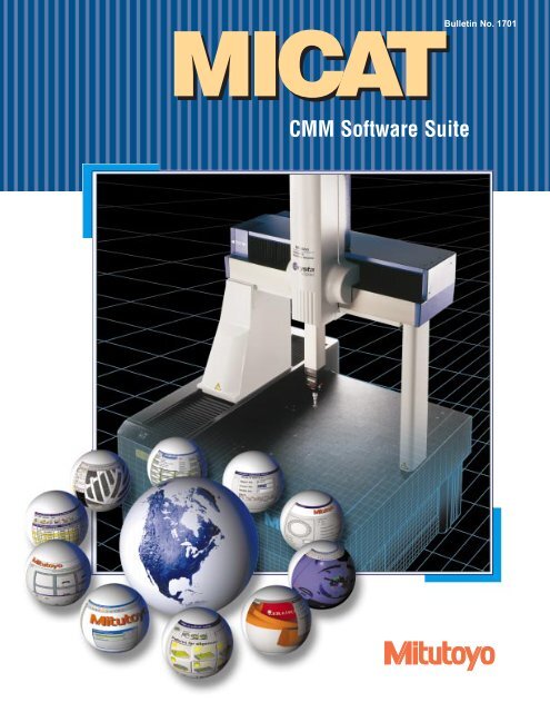
CMM Software Suite MICAT - Mitutoyo America Corporation
CMM Software Suite MICAT - Mitutoyo America Corporation
CMM Software Suite MICAT - Mitutoyo America Corporation
- No tags were found...

You also want an ePaper? Increase the reach of your titles
YUMPU automatically turns print PDFs into web optimized ePapers that Google loves.
<strong>MICAT</strong>-C1TolerancingAll features measured in <strong>MICAT</strong> can be compared against tolerancesstipulated in the final design helping to ensure total quality control ofyour products.Full Geometric Drawing Tolerancing (GDT) commandsare available. Orientation (Parallelism, Perpendicularity,etc.) can be assessed along with the form error of the features(Circularity, Flatness, etc.). A scaled graphical outputhighlights problem areas; deviations from the true geometricalform can be magnified to aid visualization.. Setting Tolerances for Elements. Tolerance ResultsRepetitive Tasks made easyIt is also possible to easily set up variety of customized on-line macrosfor regularly used instruction sets so that certain routines are instantlyavailable. <strong>MICAT</strong> automatically defaults to the last-used setting ratherthan requiring the user to reset parameters every time a measuring programis written, ensuring that the operator is as productive as possible.<strong>MICAT</strong> also features an ASCII converter that converts part programscreated by an external program into the internal <strong>MICAT</strong> format, givingyour system total flexibility as well as the ability to easily upgrade,while still being able to use files from your old system.Operator AssistanceTo assist operators, the software constantly displays the current. Tolerance Measurement Report machine position and temperature for those machines with the temperaturecompensation function.The attitude of the current co-ordinate system can also be displayedand with a 'Picture & Sound' function, users can define their own setof instructions for machine operators, producing a fail-safe part program.The temperature compensation function is used to maintainaccuracy if the machine is located in an area with temperature fluctuationsor if the component being measured is abnormally warm orcold. The operator simply enters the expansion co-efficient for thematerial being measured and results are then calculated at the standard. Machine Position and Temperaturemeasuring temperature of 20 degrees C.Data OutputResults can be output to a file, reported to SPC software or printed ina comprehensive standard layout. Alternatively, users can define theirown layout using the Protocol Manager of <strong>MICAT</strong>.5. Entering Expansion Coefficient
<strong>MICAT</strong>-C1Protocol DesignerProtocol Designer provides users with the means to adapt measurementreports to suit their requirements. <strong>MICAT</strong> includes some example formatsand also standard Initial Sample Inspection Report layouts thatcan be used or modified to suit.The reports can be printed automatically following the <strong>MICAT</strong> measurementprogram or archived and printed at a future date. Additionalinformation such as supplier, batch or lot numbers can be recorded onthe report via user defined dialogue boxes. Again these boxes can bedisplayed during the <strong>MICAT</strong> part program for the operator to enter thedata or it can be subsequently entered in Protocol Designer.. Graphical Representation of Results. Report Output SettingQ-Pak (Option)Designed to further simplify the <strong>CMM</strong> measurementprocess for the shop floor, Q-Pak allows the <strong>CMM</strong> to runas a measurement gage.Locations are pre-defined on the <strong>CMM</strong> table; these can be fixtures ora simple grid arrangement. Operators select a free location and positionthe part for measurement, and then enter the part program to runat that specific location. Part programs run consecutively leaving theoperator to attend to other tasks, returning later to collect the measurementresults and if required, enter a new part to be measured. Thenumber of table locations is only restricted by the <strong>CMM</strong> table size.If a part needs to be measured urgently, there is a password optionwhich allows the operator to 'jump' the queue and move any part to thefront or move other parts to the back of the queue. Q-Pak allows the<strong>CMM</strong> to run virtually without any manual operation. The addition ofa touch-screen, or bar-code reader can further simplify its use.. Parameter Setting. Main Screen Shot6
<strong>MICAT</strong>-C3 3-D CAD Surface Evaluation Function<strong>MICAT</strong>-C3 includes a 3D Surface program that allowstolerance comparisons between measured points andnominal CAD data. Measured results are displayedgraphically in 'Real-Time' and are color coded dependingon the deviation, allowing operators to immediately seeproblem areas.Model data is imported from a range of CAD systems using a variety ofexchange formats. The CAD model is displayed in a 3D viewer, completewith its elements information, where standard tools allow the userto zoom, pan or rotate the graphic model to provide the most suitableview.The reference coordinate system can be set using the CAD data; coordinatestaken from the model being used to complete the alignment inGeopak-Win so the part and the CAD origin coincide. The origin positioncan then be transposed or rotated to a more suitable position formeasurement.Real-Time MeasurementThe results of each measured point is displayed in a table showing the X,Y and Z deviations as well as the 'surface normal' deviation alongside thereference CAD data point. Deviations are color-coded based on theamount of the tolerance used enabling fast evaluation. Colors may beuser-defined as a percentage of the tolerance. In addition to displayingthe measured points summary window, minimum, maximum and averagedeviations are also shown. A histogram summarizes the dispersionof the deviations against the nominal data.Automatic Measurement<strong>MICAT</strong>-C3 is able to use the CAD data to control the movements ofCNC <strong>CMM</strong>'s. Individual points can simply be selected by a mouse clickon the CAD viewer. The coordinates are displayed and the user then hasthe option to either measure the selected point or send the data toGeopak-Win for subsequent use. For surfaces, a measurement grid utilityallows rapid data collection of multiple positions. The user selects thesurface to be measured and determines the grid width and height.<strong>MICAT</strong>-C3 then calculates points to be measured on the surface, displaysthe points in the viewer for confirmation and then measures the points,displaying the results.As the topography of the model is known, features such as holes areautomatically avoided eliminating the risk of collisions. <strong>MICAT</strong>-C3 alsosimplifies Geometry measurement, the feature to be measured, alongwith the start/end points. Other relevant information can be determinedby selecting points on the CAD model. The points to be measured aredisplayed to the user prior to confirmation allowing modification ifrequired. A unique calculation function determines the position of eachmeasurement point avoiding features such as slots.. Auto-Measurement of Single Point. Auto-Measurement of Cylindrical Geometric Features. Auto-Measurement of Circular Geometric Features8. Auto-Measurement of Linear Geometric Features.
<strong>MICAT</strong>-C3 3-D CAD Surface Evaluation FunctionBest Fit FunctionIf measured results show substantial deviations, a 'Best-fit' routine providesthe information required to correct the part. This function automatically'Best-fits' the measured points to the CAD model, then displaysthe shift in X,Y and Z co-ordinates along with the rotation requiredaround each axis to achieve this result. The graphical display is alsoupdated.'Best-fit' is most effective when the reference co-ordinate system is notaccurately defined to provide tool setting information.Mirrored PartsOften, to simplify CAD design, only one part of a symmetrical componentis created; this is frequently the case in the automotive industry. Inthis instance it has the ability to either mirror the CAD model about a referenceplane or around its axis in the case of rotational symmetry suchas impellers. The complete component can then be displayed in the CADviewer for analysis or measurement.. Before Best Fitting. After Best Fit. Best Fitting Function Menu. Results Histogram displayed in Real-TimeData OutputUser-defined graphical layouts clearly show the measurement resultssimplifying their interpretation, measured results can also be output as alist to file or printer. Measured points can be output inDMIS/VDAFS/IGES formats to allow CAD systems to modify theresults for reverse engineering or for the part to be checked in a CADassembly for part interference.The CAD nominal data can also be used to calculatea "section" of the model for use with the <strong>MICAT</strong>scanning. The section can then be used to compare a2D scan of the component against the nominal or tocalculate geometric properties of the section.9. Measurement Results displayed in Real-Time showing tolerance condition
<strong>MICAT</strong>-C3Evaluation for Two Dimensional Curved LinesWhere analysis of forms and shapes is required from the measuringroutine, then <strong>MICAT</strong> with the addition of the scanning is unsurpassedin performance and analysis.<strong>MICAT</strong>-C3 scanning provides high performance scanning of workpiecesand evaluation of the resultant contours. Accurate analysis canbe made quickly and efficiently and with links included to and froma whole range of CAD and Machine Tool systems, reverse engineeringis made possible, making it a very powerful software solution.The measurement of the profile or surface of the workpiece is carriedout, using the Contour Measurement Method. The use of patchesmakes surface measurement possible by defining the scan direction,area and data collection parameters.. ‘Best fitting’ helps to differentiate between form and positional errors.Samples of parts that canbe evaluated by Scanpak-WinData Analysis<strong>MICAT</strong>-C3 with scanning can compare measured data to the nominaldata obtained from a CAD system and output the deviations usingeasily interpreted graphics. The data can be manipulated to show bestfitconditions and may be used to determine offsets for the manufacturingprocess.. Contour Tolerance Window for best fitting. Tolerance Comparison Contour Window. Tolerance Result After Best FittingIn addition, powerful tools are provided for expansion or contractionof measured data, and for computing geometric elements out of thescanned results.<strong>MICAT</strong>-C3 with the scanning option supports the Renishaw SP600Mand SP25M analog scanning probes on the Renishaw PH10M indexableprobe head. In addition to the standard Renishaw touch triggerand scanning probes, <strong>MICAT</strong>-C3 also supports the superb <strong>Mitutoyo</strong>MPP100 and MPP300 digital scanning probes. Both the Renishaw and<strong>Mitutoyo</strong> probe systems are available with interchangeable magneticstylus modules and passive stylus racks.10
. Measurement Parameters<strong>MICAT</strong>-C3’s Gear Measuring is designed to measure andanalyze data for all types of gears and is completely integratedwith <strong>MICAT</strong>’s coordinate measuring, eliminating the needfor file conversion.The operator is guided through an intuitive graphical interface to input thenominal gear data and measurement conditions, such as probe type and thengenerates the gear measuring measurement program. The program can becalled from <strong>MICAT</strong> at any time to allow additional measurement routines tobe added to the Gear measurement program. Alternatively the <strong>CMM</strong> can bemounted with a batch of the same type of parts. Different parameters can bemeasured such as Profile, Helical Lead, Tooth, Thickness and Pitch, and segmentedgears are also accommodated. The user can specify which parametersto measure and even specify which teeth to evaluate. If the mating gear datais known, a simulatedrolling test can be carriedout.Gear Measuring (Option)Following measurement,the gear data can be comparedagainst gear standardsincluding ISO, DIN,. Input of Tooth conditionsAGMA and JIS.. HTML Report Screen. Gear Parameter Information tableResults are output in a range of standard protocol reportsand generated in HTML format, allowing them to beviewed on any computer with an Internet browser and thedata to be shared with suppliers, customers, developmentteams and the like.. Gear Measurement Summary of Results Table11
Non-Contact Vision Measurement (Option)QVP Data Capture Single Click Operation is another useful element. When a feature is selected, such asa point or line, the edge is automatically detected. All the operator has to do is select the relevant tool fromthe icon menu and then click near the applicable feature.In addition, every image captured by the high resolution CCD camera can be processed simply and quickly,and can be stored as a Bitmap file, which can then be used with spreadsheet or word processing softwareto produce high quality report documents.<strong>Mitutoyo</strong>'s Quick Vision Probe, which is available as a retrofit system for CNC<strong>CMM</strong>s, enables non-contact vision measurement at an affordable cost.Non Contact MeasurementWhen using the QVP with a conventional <strong>CMM</strong>, many of the restrictions of contact measurement areeliminated. Small dimensions, easily deformed plastic and rubber parts, and printed items such as PCB'scan be easily and accurately measured, compared to contact type probes. Another benefit is that heavy orlarger workpiece components that require vision measurement techniques can be easily accommodateddue to the design and construction of a conventional <strong>CMM</strong>. Coupled with sub-second vision processingspeed, the QVP significantly reduces inspection cycles, hence increasing measurement efficiency andreducing costs. A white LED illumination system is employed, which provides a range of advantages.These include quick responses to when the brightness is adjusted, in addition to a long service life. Theneed for external light sources and associated cables are eliminated as well. Minimal additional wiring tothe <strong>CMM</strong> is required, making the retrofit as easy.By using a lightweight alloy body, the overall size and weight of the probe is kept to a minimum, aidingcompatibility with conventional probes, and can be used with the current probe system that is employedon the <strong>CMM</strong>. The probe also comes in two configurations: Auto-joint connector, or straight shank type.The auto-joint type can be used with an automatic rack probe changing system, hence reducing the cycletime of a part program where both contact and non-contact measurement techniques are required.Total ControlThe system is supplied with the powerful Window's based Vision image analysis software. This runs with<strong>MICAT</strong> <strong>CMM</strong> software, giving seamless control between both contact and vision measurement. This isdesigned with an easy, intuitive interface that allows relatively inexperienced users to progress quicklywith minimal training. An auto/manual focusing function is available for edge detection as well as stepand height measurement.Single Click OperationSingle Click Operation is another useful element. When a feature is selected,such as a point or line, the edge is automatically detected. All the operator hasto do is select the relevant tool from the icon menu and then click near theapplicable feature. In addition, every image captured by the high resolutionCCD camera can be processed simply and quickly, and can be stored as aBitmap file, which can then be used with spreadsheet or word processingsoftware to produce high quality report documents.12. QVP Data Capture. QVP in action
MeasurLink ® (Option)Now available for SPC analysis, <strong>Mitutoyo</strong>'s MeasurLink ® QualityManagement <strong>Software</strong> combines real-time data acquisition, on-line SPCanalysis, integrated networking, and quality information sharing into a comprehensivesolution for your company.The MeasurLink ® suite consists of a number of different software modulesthat allow users to determine the level of depth they want in a quality managementsystem.MeasurLink ® has a wide range of capabilities, performing as a data acquisitionclearing house by enabling users to connect and acquire data from virtuallyany measuring device.It supports <strong>CMM</strong>, Form Measuring Products and Vision Systems, in additionto a full array of other tools including Calipers, Micrometers, Indicators,Height Gages and more. They can be networked into one large quality analysissystem with the ability to provide manufacturing QC data to a variety ofinformation users in the company.MeasurLink ® creates a total quality measurement system by networking<strong>CMM</strong>s as well as other metrology instruments, allowing for the acquisitionand analysis of QC data, quality management of the manufacturing process,the tracking, management and R&R of gages in use, and advanced SPCanalysis and reporting for the manufacturing entity, through modules such asSTATMeasure PLUS, Gage R&R (Repeatability and Reproducibility), SPCProcess Manager and SPC Process Analyzer.MeasurLink ® STATMeasure PLUSMeasurLink ® STATMeasure PLUS is a Real-Time DataAcquisition module for <strong>CMM</strong>s and Vision MeasuringMachines, and is the base module for a Total QualityEnvironment. This is explained in more detail opposite.MeasurLink ® Process ManagerThis module monitors all MeasurLink ® Real-Timeactivities on a computer network. It provides realtimefeedback about the behavior and control state of all networkedSPC Data Acquisition Stations across the shopfloor,giving the QC/Production Manager the perfecttool to organize and maintain a shop floor quality programat a glance.MeasurLink ® Process AnalyzerThe Process Analyzer module is an application that analyzes processperformance and capability. It gives the ability to also identify problemareas in the manufacturing environment, allowing corrective action to betaken at an early stage, with statistical data easily manipulated andunderstood within an intuitive interface.MeasurLink ® Gage R&RMeasurLink ® Gage R&R gives you all the necessary tools for conductingGage Repeatability and Reproducibility studies as defined in theMeasurement System Analysis Reference Manual for QS9000.For more information on any of the MeasurLink ® Modules, request theseparate MeasurLink ® brochure, or visit www.measurlink.com13
MeasurLink ® (Option)MeasurLink ® STATMeasure PLUSDesigned for Coordinate Measuring Machines (<strong>CMM</strong>s) and VisionMeasuring Machines (Quick Scope and Quick Vision machines). It is basedon all the functionality of the latest data acquisition software and is fully integratedwith the latest <strong>Mitutoyo</strong> <strong>CMM</strong> and Vision <strong>Software</strong>, delivering processcapability and part acceptability to operators at a glance.STATMeasure PLUS is designed to be intuitive and operatorfriendly and is capable of high volume inspection with multivariantdisplays. Unlike most of the traditional SPC softwarethat is designed for small tools, the multi-variant display inSTATMeasure PLUS allows you to view your inspectionresults in four different display types: Graphics View, ManagerSnapshot View, Manager Global Variable View and ColumnIndicator View.The Graphics View displays callout boxes against BMP, JPEG,DXF, DWG and DWF pictures. The Manager Snapshot Viewsfunction displays a grid of features (16 viewable at one time).Snapshot windows include Box-Whisker, Meter Chart,Histogram, Information (Cp, Cpk). The third view type available,Manager Global Variable View, displays a bar graph of allfeatures’ current Cpk.Finally, the column Indicator View type displays the current observation of features (20 visibleat any one time) against the tolerance limits. Graphic View callouts can include the followingoutput: Part ID, Revision, Current Observation, Cp, Cpl, Pp,Ppk, Nominal, UTL, LTL, Process Mean, Average Range, StandardDeviation, Subgroup and Observational numbers, Box-Whisker, MeterChart, Histogram, Indicator Bar, Control Indicator Light and simpleGo/NG display.In addition to the multi-variant view, STATMeasure PLUS allows youto see dedicated charts including Xbar & R, Xbar & S, Pre-control, RunChart, Individual and moving range, Statistics, Histogram andObservations. STATMeasure PLUS also supports Attribute and ShortRun data collection. It can also be integrated with MeasurLink's ® SPCsoftware family, such as SPC Process Analyzer and SPC ProcessManager for broader quality management.14Other Features• Wizard Start-up• Force traceability and assignable cause options• Save Window and print layout• Multi-feature column indicator view• Add traceability on the fly• Double-click subgroup summary• Single page report that contains multiplefeatures statistical summary• Data export capability• Support for multiple reading RS-232C Output• Control Limit locking• Context Sensitive help• QVP in action
<strong>MICAT</strong> Series FunctionsMANUAL <strong>CMM</strong><strong>MICAT</strong>-M1Graphical User InterfaceHigh Level BranchingPTB Certified AlgorithmsCSV file output and Protocol DesignerGraphical Representation of Measured Features<strong>MICAT</strong>-M2All <strong>MICAT</strong>-M1 Functions3D CAD Surface Evaluation FunctionAdvanced Graphical ReportingNative Download CAD Formats:VDAFSIGESSATOptional TranslatorsSTEPCATIAPro/EParasolidUnigraphics<strong>MICAT</strong>-M3All <strong>MICAT</strong>-M1 and M2 functionsEvaluation for Two Dimensional Curved LineBi-directional CAD/NC Tool Path CommunicationsNative Download CAD Formats:VDAFSIGESSATOptional TranslatorsSTEPCATIAPro/EParasolidUnigraphicsCNC <strong>CMM</strong><strong>MICAT</strong>-C1Graphical User InterfaceHigh Level BranchingPTB Certified AlgorithmsCSV file output and Protocol DesignerGraphical Representation of Measured Features<strong>MICAT</strong>-C2All <strong>MICAT</strong>-C1 FunctionsGraphical Programming from CADNative Download CAD Formats:VDAFSIGESSATOptional TranslatorsSTEPCATIAPro/EParasolidUnigraphics<strong>MICAT</strong>-C3All <strong>MICAT</strong>-C1 and C2 functions3D CAD Surface Evaluation FunctionAdvanced Graphical ReportingEvaluation for Two Dimensional Curved LineBi-directional CAD/NC Tool Path CommunicationsNative Download CAD Formats:VDAFSIGESSATOptional TranslatorsSTEPCATIAPro/EParasolidUnigraphicsOPTIONSMeasurLink for all <strong>MICAT</strong>Q-Pak for All <strong>MICAT</strong>-CCorrect Plus for all <strong>MICAT</strong>-CNon-Contact Vision Measurement for All <strong>MICAT</strong>-CConvert the DMIS File (IN/OUT) for <strong>MICAT</strong>-C2 and C-3Gear Measuring for <strong>MICAT</strong>-C3
<strong>Mitutoyo</strong> <strong>America</strong> <strong>Corporation</strong>www.mitutoyo.comRegional Offices Michigan Illinois CaliforniaPhone: (734) 459-2810 Phone: (630) 978-5385 Phone: (626) 961-9661Massachusetts Indiana North CarolinaPhone: (978) 692-8765 Phone: (317) 577-6070 Phone: (704) 875-8332© 2003 <strong>Mitutoyo</strong> <strong>America</strong> <strong>Corporation</strong>, Aurora IL We reserve the right to change specifications and prices without notice. 10B-4 • Printed in USA • October 2003