SurfaceMeasure - Mitutoyo America Corporation
SurfaceMeasure - Mitutoyo America Corporation
SurfaceMeasure - Mitutoyo America Corporation

Create successful ePaper yourself
Turn your PDF publications into a flip-book with our unique Google optimized e-Paper software.
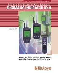
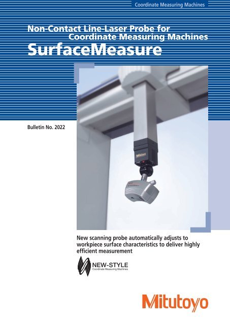
Non-Contact Line-Laser Probe Made by <strong>Mitutoyo</strong>Now you can measure a workpiece without being concerned about its color toneor glossiness.Automatic Beam Intensity Measurement and High-Speed ScanningThe <strong>SurfaceMeasure</strong> is a lightweight, high-performance, non-contact, line-laser probe developed for usewith CNC coordinate measuring machines. The use of digital signals has eliminated the effects of signaldeterioration on measurement accuracy and also improved measuring speed.Furthermore, by automatically adjusting the laser intensity and camera sensitivity according to theenvironment and the workpiece material, the <strong>SurfaceMeasure</strong> has achieved automatic beam intensitymeasurement, providing a simpler and more comfortable laser-scanning environment.High-Speed Scanning■Positioning control in a maximum of 720 directions enableshigh-speed scanning of even complex workpieces in theoptimum orientation.Additionally, the use of ACR3* allows you to make fullyautomated measurements while selecting “non-contact”and “contact” probes as desired.• Using the ACR3 equipped with a power supply port for the laserprobe, which can be specially ordered, eliminates the need forwarming up the laser probe.Automatic Intensity Adjustment■Since the laser intensity and camera sensitivity areautomatically adjusted, stable shape data can be obtainedeven when the workpiece has multiple colors and varyingdegrees of reflectance.紫銀銅金緑赤青黒Measuring a color-sample plate*ACR3 is a trademark of Renishaw plc.■The <strong>SurfaceMeasure</strong>, with a measuring area of 2.36"(60mm)(W) x 2.36"(60mm) (D), captures data at the rate of 75 lines/sec.Measuring a glossy object0.023(0.06mm) minimum pitch2.36(60mm)2.36(60mm)*Line pitch (variable) 0.06mmMeasuring area 177.3(4,500mm²/s)At a line pitch of .04(1mm)75lines/sec2.36(60mm)3
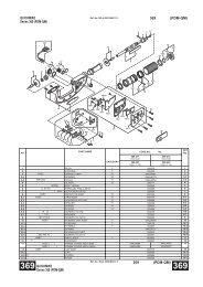
Providing Measurement Solutions with Non-Contact Line-Reducing the measurement, inspection, and analysis processes through high-speed data collection.User-friendly point cloud data processing softwareEvaluation based on non-contact measurement begins with the processof accurately capturing the surfaces of the product that has been formed.The high-density point cloud data obtained from the surface of a partis utilized by evaluation software programs for data analysis purposes,such as extraction of geometric elements, evaluation of free-formsurfaces and profile shapes, and comparison with master data.Furthermore, utilizing the obtained data in reverse engineering canrevitalize the creative and manufacturing cycle that uses 3D data asits core.Scanning: MSURF-S■Scanning paths can be created by simply defining three items:the scanning starting point, the scanning length, and thescanning width.• You can easily define these three items using the joystick whilechecking the camera preview.• If point cloud data or master data is displayed on the screen, youcan define the three items using the mouse on the data. Thisfeature is convenient for creating a measurement path based onsimulation and for specifying areas where data needs to be remeasured,both of which are useful in reducing the number ofmeasurement steps. These operations can be easily carried outusing the joystick.■Point cloud data obtained from scanning can be exported intext or STL format.• This data can also be processed using various kinds of softwareprograms designed for processing point cloud data.■MSURF-S can be started from MCOSMOS• Since a work coordinate system created in MCOSMOS can beutilized by MSURF-S, you can execute fully automatic measurementsthat merge “contact” and “non-contact” measurements.■Scanning paths can be registered as measurement macros.• You can use the override function to modify all or some of themeasurement conditions in the created measurement macros.• The submacro function is effective for measuring multiple units ofthe same workpiece.• The execution time of a measurement macro is computed from themeasurement conditions and the coordinate measuring machinespecifications.Note: If ACR3 is not used, the probe must be manually changed.4
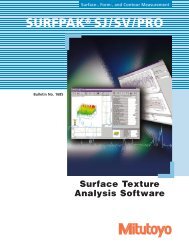
Laser Probes to Strengthen Manufacturing CapabilityEnabling easy measurement of curved shapes, producing data that can be used in reverse engineering.Inspection: MSURF-I■Importing CAD data• Support of IGES, STL, and SAT formats is standard.• Optional formats available include CATIA V4, CATIA Variable,ProEngineer, Unigraphics, STEP, and VDAFS.■Feature-by-feature comparison• You can detect various features from point cloud data or meshdata and compare them to the design data. From featurescontaining point data, such as a circle, you can calculate thedimensions between the features.• Features that can be detected include the basic elements such asplanes, points, straight lines, slots, cylinders, circular cones andspheres as well as welded bolts, welded nuts, cylindrical pins,T-studs, etc.■Comparison of cross-sectional shapes• You can cut point cloud data or mesh data to compare crosssectionalshapes or compute angles, distances, radii, etc.• Additionally, the optional turbine blade analysis function cancompute the LE thickness, TE thickness, maximum thickness,chord length, etc.Cross-sectional evaluation (dimension computation)Turbine blade analysis (optional function)■Planar shape comparison• Point cloud data or mesh data can be compared with CAD data,and the planar shape errors displayed on a color map.• Since wall thicknesses can be displayed on a color map, there isno need to cut the workpiece as is necessary with conventionalmethods.• A simulated digital caliper function enables quick evaluation of awide variety of steps and gaps.• When evaluating the curvature of a surface, the angle R within thespecified tolerance, for example, can be evaluated.■Creation of an operating procedure macro using theautomation function• The automation function can record the operating procedure,including the execution of measurement macros.This function allows you to automate a series of operations, frommeasurement, to evaluation, to report creation.Color map of errors Color map of wall thickness Evaluation of steps and gapsEvaluation of surface curvature5
Off-line teaching software to improve work efficiencyIf model data is available, you can create measurement macros even if you don’t havethe actual workpiece.Off-line teaching: MSURF-GSince MSURF-G can use model data to create measurement macros,measurement operations can start immediately when the actualobject is ready.MSURF-G increases the availability factor of measuring machines and,when combined with MSURF-I, significantly reduces the number ofprocess steps in everything from measurement to product evaluation.• Reduces the time the CMM was previously occupied in the creation of measurement macros.• Allows easy creation of measurement macros, regardless of the skill level of the operator.• Optimizes workflow from measurement to evaluation.■Semi-automatic function for creating measurement pathswith optimum probe orientation• To create a measurement path, simply specify a single point on themodel.• The optimum scanner orientation is automatically selected.• This function creates new measurement paths while avoiding areaswhere measurement paths have already been created.*On sheet metal, the semi-automatic function can be used onapproximately 95% of the entire area.■Detection of collision between the “laser probe + probe head”and the model• When a collision is detected, the collision area is displayed in redand the collision information is output in an inspection tree.*Collision with the spindle cannot be detected.Output of scan information containing a detected collision.■Generation of simulated data for the point cloud dataexpected to be obtained through scanning• Creates point cloud data on work models while adjusting forthe measurement conditions (scanner orientation, measurementpitch, overlap, etc.), the camera’s blind spots (the laser projectiondirection and the position of the model), and the scannerconditions (effective field of view, reflection angle, etc.).When a collision is detected, the area is displayed in red.■Displaying measurement movements (scanner movements)in animation• Replays the measurement movements at an appropriate speed byadjusting for the type of scanner being used and the stripe pitch.• A slider can be used toadjust the speed at whichthe scanner movements aredisplayed. The animation canalso be advanced or reversed.■When a measurement macro is created, the macroexecution time is estimated. This time is calculated fromthe measurement conditions and the coordinate measuringmachine used, resulting in a value close to the actual time.6
One Number to Serve You Better1-888-MITUTOYO (1-888-648-8869)Note: All information regarding our products, and in particular the illustrations, drawings, dimensional and performance datacontained in this printed matter as well as other technical data are to be regarded as approximate average values. We thereforereserve the right to make changes to the corresponding designs. The stated standards, similar technical regulations, descriptionsand illustrations of the products were valid at the time of printing. In addition, the latest applicable version of our General TradingConditions will apply. Only quotations submitted by ourselves may be regarded as definitive.<strong>Mitutoyo</strong> products are subject to US Export Administration Regulations (EAR). Re-export or relocation of our products may requireprior approval by an appropriate governing authority.Trademarks and RegistrationsDesignations used by companies to distinguish their products are often claimed as trademarks. In all instances where <strong>Mitutoyo</strong><strong>America</strong> <strong>Corporation</strong> is aware of a claim, the product names appear in initial capital or all capital letters. The appropriate companiesshould be contacted for more complete trademark and registration information.Aurora, Illinois(Corporate Headquarters)Westford, MassachusettsHuntersville, North CarolinaMason, OhioPlymouth, MichiganCity of Industry, California© 2011 <strong>Mitutoyo</strong> <strong>America</strong> <strong>Corporation</strong>, Aurora IL 3M - 0111-14 Printed in USA, May 2011