- Page 1 and 2: Leica PhotogrammetrySuiteProject Ma
- Page 3 and 4: Table of ContentsTable of Contents
- Page 5 and 6: Prepare the Block File . . . . . .
- Page 7 and 8: Generate Pyramid Layers . . . . . .
- Page 9 and 10: Editing Exterior Information for Mu
- Page 11 and 12: References. . . . . . . . . . . . .
- Page 13 and 14: List of FiguresFigure 1: Topography
- Page 15 and 16: Figure 104: Sensor Tab for IKONOS S
- Page 17 and 18: List of TablesTable 1: LPS Menu Bar
- Page 19 and 20: PrefaceAbout This ManualThe Leica P
- Page 21 and 22: IntroductionLPS Project Manager/ 1
- Page 23 and 24: Introduction to LPS Project Manager
- Page 25 and 26: LPS ProjectManagerFunctionalityTria
- Page 27 and 28: Airborne GPS and inertial navigatio
- Page 29 and 30: ToolbarThe following icons are loca
- Page 31 and 32: Photogrammetric TheoryLPS Project M
- Page 33 and 34: Introduction to PhotogrammetryIntro
- Page 35 and 36: Figure 3: LPS Project Manager Point
- Page 37 and 38: See “The Collinearity Equation”
- Page 39 and 40: Classic aerial triangulation using
- Page 41 and 42: Each photograph or image that is ex
- Page 43 and 44: Scanning ResolutionsOne of the prim
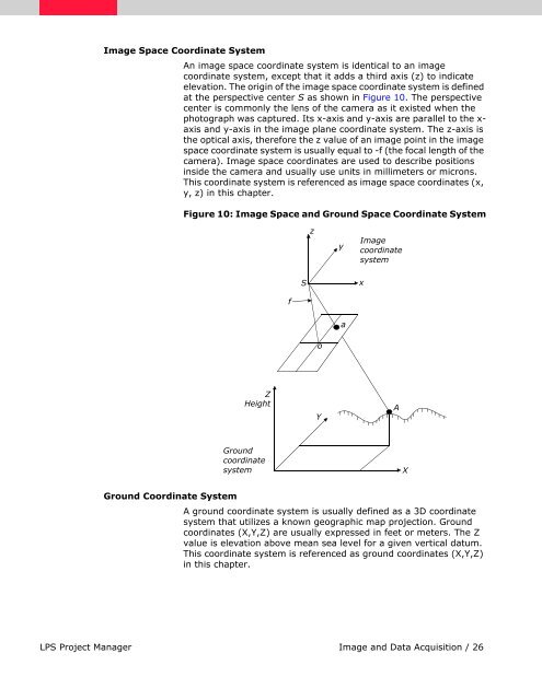
- Page 45: Coordinate SystemsConceptually, pho
- Page 49 and 50: • principal point• focal length
- Page 51 and 52: For more information, see “Fiduci
- Page 53 and 54: Figure 16: Omega, Phi, and Kappazyz
- Page 55 and 56: Figure 19: Tertiary Rotation Kappa
- Page 57 and 58: In order for the image and ground v
- Page 59 and 60: Space ForwardIntersectionSpace forw
- Page 61 and 62: Figure 21: Photogrammetric Configur
- Page 63 and 64: X o2, Y o2, Zo 2If three GCPs have
- Page 65 and 66: A = the matrix containing the parti
- Page 67 and 68: The effect of the automatic error d
- Page 69 and 70: Figure 23 illustrates the GCP confi
- Page 71 and 72: Another issue of automated triangul
- Page 73 and 74: aaρ=∑i,j∑i,jIn the above equat
- Page 75 and 76: Relation-based MatchingImage Pyrami
- Page 77 and 78: Figure 28: Perspective Centers of S
- Page 79 and 80: Figure 30: Interior Orientation of
- Page 81 and 82: Figure 31: Inclination of a Satelli
- Page 83 and 84: • the changes of angles along the
- Page 85 and 86: Figure 35: OrthorectificationImageD
- Page 87 and 88: LPS Project Manager Tour GuidesLPS
- Page 89 and 90: Frame Camera Tour GuideIntroduction
- Page 91 and 92: Access LPS toolsusing the toolbarTh
- Page 93 and 94: Click the Setbutton to openthe Proj
- Page 95 and 96: Next, you choose the images that ma
- Page 97 and 98:
Click the lastfile in therange to a
- Page 99 and 100:
Click OK tostart computingpyramid l
- Page 101 and 102:
Add Fiducial Marks1. Click the Fidu
- Page 103 and 104:
A Main View opens on top of the Fra
- Page 105 and 106:
LPS Project Manager movesto the nex
- Page 107 and 108:
LPS Project Manager returnsto the f
- Page 109 and 110:
The Image File Name on the Sensor t
- Page 111 and 112:
This is the reference CellArray: re
- Page 113 and 114:
Specify the Type and Usage1. Click
- Page 115 and 116:
1. Using Figure 46 on page 130 as a
- Page 117 and 118:
Collect Point ID 1003 in col91p1Now
- Page 119 and 120:
1. In the Point Measurement tool pa
- Page 121 and 122:
Collect Point ID 1005The next contr
- Page 123 and 124:
3. Click in the Point ID column and
- Page 125 and 126:
Collect Point ID 2001Like control p
- Page 127 and 128:
2. Click in the Usage column to acc
- Page 129 and 130:
All of the Point IDs are listedin t
- Page 131 and 132:
After the tie point generation proc
- Page 133 and 134:
Perform AerialTriangulationNow that
- Page 135 and 136:
Check the ResultsScroll to see allo
- Page 137 and 138:
These are the photo or image coordi
- Page 139 and 140:
The Ext. column is green, indicatin
- Page 141 and 142:
Resample methoddisplays hereTo add
- Page 143 and 144:
You can also use the Project Graphi
- Page 145 and 146:
Select multiple imagesto add to the
- Page 147 and 148:
Click on the sliderand move the mou
- Page 149 and 150:
Reference ImagesFigure 45: Referenc
- Page 151 and 152:
Figure 47: Reference Image of col92
- Page 153 and 154:
Digital Camera Tour GuideIntroducti
- Page 155 and 156:
Access LPS toolsusing the toolbarTh
- Page 157 and 158:
The information you supply inthe Cu
- Page 159 and 160:
Select the .datfile for exteriorori
- Page 161 and 162:
Add Imagery tothe BlockThe CellArra
- Page 163 and 164:
You are returned to the LPS Project
- Page 165 and 166:
You can savethis camerainformationf
- Page 167 and 168:
Pixel size is applied to all images
- Page 169 and 170:
1. On the LPS Project Manager toolb
- Page 171 and 172:
Click the Distribution tab3. In the
- Page 173 and 174:
4. Click the Close button in the Po
- Page 175 and 176:
12. Click the Report button in the
- Page 177 and 178:
The Point IDs are listed below each
- Page 179 and 180:
Select the image to display in the
- Page 181 and 182:
The Add Multiple Outputs dialog ope
- Page 183 and 184:
The highlighted ortho is indicated
- Page 185 and 186:
The imagesoverlap hereUse the Swipe
- Page 187 and 188:
Columns are green; the project is c
- Page 189 and 190:
SPOT Pushbroom Sensor Tour GuideInt
- Page 191 and 192:
Access LPS toolsusing the toolbarTh
- Page 193 and 194:
The Custom tab is where you select
- Page 195 and 196:
The image is listedin the Image Nam
- Page 197 and 198:
Click OK3. Review the fields in the
- Page 199 and 200:
Click OKClickImage LayerNOTE: An ex
- Page 201 and 202:
Collect GCPsIn this section, you ar
- Page 203 and 204:
5. Move the cursor into the Detail
- Page 205 and 206:
4. Click the Create Point icon .5.
- Page 207 and 208:
6. Check your point coordinates. Th
- Page 209 and 210:
2. Using the following table, type
- Page 211 and 212:
Collect Point ID 9 Figure 58: Locat
- Page 213 and 214:
The new reference image is added to
- Page 215 and 216:
6. Check your point coordinates. Th
- Page 217 and 218:
Set the VerticalReference SourceTo
- Page 219 and 220:
Set Type and UsageUp until this poi
- Page 221 and 222:
2. Click in the red column labeled
- Page 223 and 224:
Use the locations of the points in
- Page 225 and 226:
4. Click the approximate point in t
- Page 227 and 228:
The Z value is updated, makingthe c
- Page 229 and 230:
Check Tie Point AccuracyYou should
- Page 231 and 232:
The value 15 is used because the re
- Page 233 and 234:
The Ext. columns are green, indicat
- Page 235 and 236:
Click this checkbox so that the sec
- Page 237 and 238:
The highlighted ortho is indicated
- Page 239 and 240:
If you wish, you can click the View
- Page 241 and 242:
Steps have been executed; the block
- Page 243 and 244:
GCP Map Coordinates GCPs are accura
- Page 245 and 246:
Stereo Point Measurement Tool TourG
- Page 247 and 248:
If you are not prompted and the Cla
- Page 249 and 250:
Check DeviceSetupIf you have a digi
- Page 251 and 252:
12. Click Close in the Devices dial
- Page 253 and 254:
6. Click the Create Point icon in t
- Page 255 and 256:
Use the stereoview to locatethe poi
- Page 257 and 258:
4. Click the Create Point icon in t
- Page 259 and 260:
11. Compare your image point X and
- Page 261 and 262:
Each check point now has image coor
- Page 263 and 264:
Practical ApplicationsLPS Project M
- Page 265 and 266:
Getting Started with LPS Project Ma
- Page 267 and 268:
LPS Project ManagerOnce you click t
- Page 269 and 270:
Frame cameras, digital cameras, vid
- Page 271 and 272:
Orbital PushbroomThe Orbital Pushbr
- Page 273 and 274:
A standard set of existing projecti
- Page 275 and 276:
Rotation System SupportLPS Project
- Page 277 and 278:
Figure 72: Average Flying Height of
- Page 279 and 280:
• Existing photogrammetric workst
- Page 281 and 282:
Figure 75: Import Options for Exter
- Page 283 and 284:
Figure 77: The LPS Project Manager
- Page 285 and 286:
Icons are located on the toolbar at
- Page 287 and 288:
Adding Images to the BlockIntroduct
- Page 289 and 290:
Five additional columns represent t
- Page 291 and 292:
Defining the Camera or Sensor Model
- Page 293 and 294:
Figure 84: Image File in the Image
- Page 295 and 296:
• Focal length (mm). The focal le
- Page 297 and 298:
Fiducials for Digital, Video, and N
- Page 299 and 300:
Interior orientation is semi-automa
- Page 301 and 302:
Figure 90: Fiducial Orientation of
- Page 303 and 304:
The data strip commonly contains in
- Page 305 and 306:
Figure 95: Contrast Adjust DialogTh
- Page 307 and 308:
• the status of each exterior ori
- Page 309 and 310:
The Exterior Orientation Parameter
- Page 311 and 312:
Figure 99: CellArray Formula Dialog
- Page 313 and 314:
Uses of Model ParametersPolynomial
- Page 315 and 316:
The software looks for the RPC file
- Page 317 and 318:
Measuring GCPs, Check Points, and T
- Page 319 and 320:
Figure 108: Set Data Scaling Dialog
- Page 321 and 322:
A check point is used to independen
- Page 323 and 324:
Defining theStatistical Qualityof G
- Page 325 and 326:
2. Select the Image Layer option in
- Page 327 and 328:
7. Within the Right View tools grou
- Page 329 and 330:
Automatic Tie Point CollectionIntro
- Page 331 and 332:
Performing Automatic TiePoint Colle
- Page 333 and 334:
Table 8: Photography Scale and Asso
- Page 335 and 336:
• coefficient limit (0 to 0.99)
- Page 337 and 338:
t1t2∆aah∆dd∆d =∆d =--------
- Page 339 and 340:
Figure 119: Kappa as a Function1 Im
- Page 341 and 342:
Block TriangulationIntroductionBloc
- Page 343 and 344:
• X, Y, and Z coordinates of the
- Page 345 and 346:
It is advantageous to assign unique
- Page 347 and 348:
SCBA is most commonly used in the f
- Page 349 and 350:
Different UnweightedCorrectionsThis
- Page 351 and 352:
Figure 124: Advanced Options Tab of
- Page 353 and 354:
Statistical constraints can be assi
- Page 355 and 356:
• RMS error of the check point ph
- Page 357 and 358:
......Six affine transformation par
- Page 359 and 360:
If the exterior orientation paramet
- Page 361 and 362:
Interior Orientation ParametersThe
- Page 363 and 364:
Check Point ResidualsCheck points a
- Page 365 and 366:
.2041 1.9419 1.6884 3.0368 3.9804 2
- Page 367 and 368:
Figure 125: A GCP Configuration for
- Page 369 and 370:
• Map space. This display mode di
- Page 371 and 372:
The reason that we consider only k
- Page 373 and 374:
02x max2y max+= -------------------
- Page 375 and 376:
Figure 129: Advanced Options Tab of
- Page 377 and 378:
The x and y image coordinate residu
- Page 379 and 380:
y: 3.69353383e+0061.13621691e+0032.
- Page 381 and 382:
The information for each image coor
- Page 383 and 384:
gcp 1 0.00006974 -0.00020760-0.0710
- Page 385 and 386:
OrthorectificationIntroductionThe o
- Page 387 and 388:
In the case of adding a single imag
- Page 389 and 390:
Once the settings are accurate, you
- Page 391 and 392:
AppendicesLPS Project Manager/ 371
- Page 393 and 394:
Batch ProcessingIntroductionWhen yo
- Page 395 and 396:
Execute MultipleFiles/SingleCommand
- Page 397 and 398:
Other BatchApplicationsAfter you ha
- Page 399 and 400:
ReferencesIntroductionReferences an
- Page 401 and 402:
von Bündelblockausgleichungen.”
- Page 403 and 404:
http://www.atlas.gc.ca/english/cart
- Page 405 and 406:
Columbia, 1997.Yang and Williams 19
- Page 407 and 408:
Photogrammetric GlossaryAbbreviatio
- Page 409 and 410:
TermsAAdditional parameter (AP). In
- Page 411 and 412:
Block of photographs. Formed by the
- Page 413 and 414:
Coordinate system. “A system, bas
- Page 415 and 416:
See alsoDigital photogrammetryDigit
- Page 417 and 418:
Free-weighted iterative adjustment.
- Page 419 and 420:
Konrady coefficients. Coefficients
- Page 421 and 422:
Orientation angle. The angle betwee
- Page 423 and 424:
Redundancy. In a block of data, the
- Page 425 and 426:
Stereopair. A set of two remotely-s
- Page 427 and 428:
IndexSymbols.blk file 72, 136, 171.
- Page 429 and 430:
Model Setup 72, 136, 172Ortho Resam
- Page 431 and 432:
Interior Orientation tab (fiducial
- Page 433 and 434:
Select Point icon 182, 183, 186Self


![TAVAK [Kompatibilitási mód]](https://img.yumpu.com/31087107/1/190x135/tavak-kompatibilitasi-mad.jpg?quality=85)