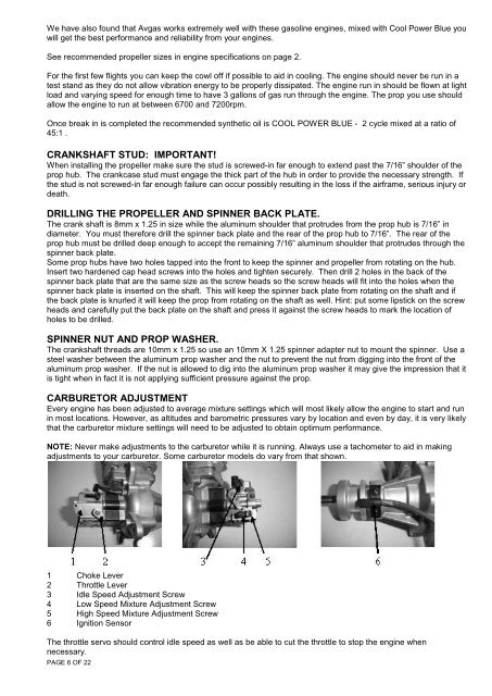
We have also found that Avgas works extremely well with these gasoline engines, mixed with Cool Power Blue youwill get the best performance and reliability from your engines.See recommended propeller sizes in engine specifications on page 2.For the first few flights you can keep the cowl off if possible to aid in cooling. The engine should never be run in atest stand as they do not allow vibration energy to be properly dissipated. The engine run in should be flown at lightload and varying speed for enough time to have 3 gallons of gas run through the engine. The prop you use shouldallow the engine to run at between 6700 and 7200rpm.Once break in is completed the recommended synthetic oil is COOL POWER BLUE - 2 cycle mixed at a ratio of45:1 .CRANKSHAFT STUD: IMPORTANT!When installing the propeller make sure the stud is screwed-in far enough to extend past the 7/16” shoulder of theprop hub. The crankcase stud must engage the thick part of the hub in order to provide the necessary strength. Ifthe stud is not screwed-in far enough failure can occur possibly resulting in the loss if the airframe, serious injury ordeath.DRILLING THE PROPELLER AND SPINNER BACK PLATE.The crank shaft is 8mm x 1.25 in size while the aluminum shoulder that protrudes from the prop hub is 7/16” indiameter. You must therefore drill the spinner back plate and the rear of the prop hub to 7/16”. The rear of theprop hub must be drilled deep enough to accept the remaining 7/16” aluminum shoulder that protrudes through thespinner back plate.Some prop hubs have two holes tapped into the front to keep the spinner and propeller from rotating on the hub.Insert two hardened cap head screws into the holes and tighten securely. Then drill 2 holes in the back of thespinner back plate that are the same size as the screw heads so the screw heads will fit into the holes when thespinner back plate is inserted on the shaft. This will keep the spinner back plate from rotating on the shaft and ifthe back plate is knurled it will keep the prop from rotating on the shaft as well. Hint: put some lipstick on the screwheads and carefully put the back plate on the shaft and press it against the screw heads to mark the location ofholes to be drilled.SPINNER NUT AND PROP WASHER.The crankshaft threads are 10mm x 1.25 so use an 10mm X 1.25 spinner adapter nut to mount the spinner. Use asteel washer between the aluminum prop washer and the nut to prevent the nut from digging into the front of thealuminum prop washer. If the nut is allowed to dig into the aluminum prop washer it may give the impression that itis tight when in fact it is not applying sufficient pressure against the prop.CARBURETOR ADJUSTMENTEvery engine has been adjusted to average mixture settings which will most likely allow the engine to start and runin most locations. However, as altitudes and barometric pressures vary by location and even by day, it is very likelythat the carburetor mixture settings will need to be adjusted to obtain optimum performance.NOTE: Never make adjustments to the carburetor while it is running. Always use a tachometer to aid in makingadjustments to your carburetor. Some carburetor models do vary from that shown.1 Choke Lever2 Throttle Lever3 Idle Speed Adjustment Screw4 Low Speed Mixture Adjustment Screw5 High Speed Mixture Adjustment Screw6 Ignition SensorThe throttle servo should control idle speed as well as be able to cut the throttle to stop the engine whennecessary.PAGE 6 OF 22
The average mixture settings are 1&1/2 turns out for the low speed circuit (See No. 4), and 1&3/4 turns out for thehigh speed circuit (See No. 5). Carburetor mixture adjustment starts with the low speed circuit. The low speedshould be set such that the transition from idle to full throttle is smooth, even if the throttle is snapped to full. Thiswill likely result in a slightly rich idle mixture but you're better off with that than a rough transition. If the engine dieswhen the throttle is advanced, the mixture is likely too lean. If the engine stumbles when the throttle is advanced,the mixture is likely too rich. Since the low speed mixture has some effect on high speed mixture, always adjust thehigh speed after adjusting the low.The high speed circuit is properly adjusted when the engine can reach maximum rpm while in the air, which isusually slightly richer than when it is on the ground. A general rule of thumb is to richen from the maximum on theground rpm by about 200rpm. If ever the engine slows or dies while at full throttle, the high speed mixture is likelytoo lean and you should adjust it as soon as possible or damage can result.NOTE: Be careful not to run the mixture screws in too far as damage to the screw and / or carburetor body mayresult. Also, don't be tempted to run an overly rich mixture. Gas engine lubrication comes from the oil concentrationin the gas, not from a rich fuel / air mixture. If you want more lubrication, you can vary the oil mix ratio. A too richmixture will only result in poor engine performance and a fouled plug and combustion chamber.STARTING THE ENGINECOLD Step 1: Close the choke, advance the throttle to very slightly above the idle position, turn on the ignition andbriskly flip the prop through compression until the engine fires and then dies. If the gas line is dry, this may take 20or more flips.Step 2: Open the choke and briskly flip the prop through compression. The engine should start in just a few flips. Ifit acts like it wants to start but doesn't, you may need to advance the throttle slightly.WARM Open the choke, advance the throttle to very slightly above the idle position, turn on the ignition and brisklyflip the prop through compression. The engine should start in just a few flips. If it acts like it wants to start butdoesn't, you may need to advance the throttle slightly.NOTE: It is possible to flood the engine by over choking. In this case, the spark plug must be removed and dried ofexcess fuel. Make sure to have the ignition off when removing the spark plug.ENGINE MAINTENANCEFuel tubing throughout the fuel system should be changed periodically and should never allow any air to enter thesystem. If your gas line starts to get hard, soft or changes color, there's a good chance it needs to be replaced.Keep in mind that the tubing inside your tank deteriorates more quickly than anywhere else in the system.The exterior of the engine should be kept clean and inspected regularly. Tucked away inside the cowl, it would beeasy to miss loose nuts and bolts without frequent inspections. Dirt inside the cowl area can easily find its way intothe carburetor. It should be kept clean and free of dirt build up.The carburetor fuel screen should be cleaned periodically also. Carefully remove the pump cover (inlet side of thecarburetor), gasket and pump membrane. The screen will be visible and can be cleaned after careful removal. Ifever the carburetor seems to need frequent mixture adjustment or acts like it's starving for fuel, a dirty screen is alikely candidate for a cause. The carburetor should be inspected, cleaned or reconditioned with every flying seasonor after being stored for a long period of time.The spark plug should be inspected, cleaned and gapped periodically and replaced if it is fouled or worn. A newplug with every new season is a worthwhile maintenance step.ASSISTANCEAdditional information and the latest version of this manual are available at TATES PERFORMANCE HOBBIESand answers to specific questions can be obtained by email at sales@tates.com.au or by phone at 03 522 4201.#4 - Running the Engine on a Test StandThe engine mounts supplied with the DL engines are designed to be used on an airframe intended for use with a50cc/100cc gas engine. Running your engine on a test stand may very well cause them to fail. A typical test standdoes not allow the vibration energy produced by the engine to dissipate as it would if mounted in an airframe. As aresult, this energy causes undue stress to be exerted on the mounts and they will likely fail if run long enough.When properly used, the engine mounts will provide trouble free operation. Our own experience has one set oforiginal mounts still performing flawlessly after over 176hrs of vigorous use.Improper use of the engine or its parts may result in injury and property damage. Please read and follow all itemspresented in the operating instructions. This is important for your safety as well as your enjoyment of the engine.PAGE 7 OF 22