Smoke ventilation according to EN 12101-2 - D+H Mechatronic
Smoke ventilation according to EN 12101-2 - D+H Mechatronic
Smoke ventilation according to EN 12101-2 - D+H Mechatronic

You also want an ePaper? Increase the reach of your titles
YUMPU automatically turns print PDFs into web optimized ePapers that Google loves.
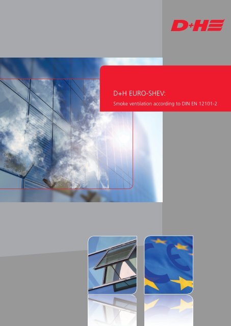
IntroductionSince September 2006, all natural smoke and heat exhaust ventila<strong>to</strong>rs (NSHEVs) must provide usability certificationin accordance with DIN <strong>EN</strong> <strong>12101</strong>-2 or be individually authorised by means of approval. Only tested completesolutions (consisting of a window or dome light and drive) may be used that in the case of standard unitshave a CE mark and in the case of cus<strong>to</strong>m-designed facades and roof designs have individual approval. DIN <strong>EN</strong><strong>12101</strong>-2 is a mandated and harmonised standard which falls in<strong>to</strong> the field of application of the ConstructionProducts Directive and soon of the Construction Products Regulation.In Germany, for example, an NSHEV must always be used when a natural smoke vent is required by building regulations.It is stipulated that the NSHEV must have an aerodynamically effective smoke vent area. If only a certaingeometric opening area (smoke extraction openings) is required for smoke extraction, an NSHEV is not required.Put your confidence in the expertise of <strong>D+H</strong> <strong>Mechatronic</strong> AG <strong>to</strong> plan and install NSHEVs! Our wide range ofcertified systems from leading system suppliers give you great flexibility when planning NSHEVs and guaranteedimplementation reliability for planning and functionality across all phases of your projects. Benefit from theincredible variety of our tested NSHEV solutions! Extremely high weights in the roof area (up <strong>to</strong> 330 kg), extremelyhigh snow loads (up <strong>to</strong> 3,000 pa) or wind loads (up <strong>to</strong> 2,000 pa) are not a problem for the NSHEVs either.In this <strong>D+H</strong> basic module you will find a large amount of information on the subject of DIN <strong>EN</strong> <strong>12101</strong>-2. We hopethis provides you with effective support when working with NSHEVs and helps you <strong>to</strong> keep track of the biggerpicture. Visit our website www.dh-partner.com as well <strong>to</strong> find out even more about our complete EURO-SHEVsystem solutions!Do you still have any questions? Our team of experts will be happy <strong>to</strong> give you advice in person.www.dh-partner.com3
ContentsIntroduction 3Table of Contents 6The <strong>D+H</strong> <strong>Mechatronic</strong> AG company 8A Useful information about <strong>EN</strong> <strong>12101</strong> 91 The <strong>EN</strong> <strong>12101</strong> series of standards using the example of Germany 102 The path <strong>to</strong> the CE marking and <strong>to</strong> the EC certificate of conformity for NSHEVs 173 Using NSHEVs in the building 304 Other product standards for smoke and heat exhaust systems 32B Calculation aids 331 Sample calculation in the roof: specification of the stroke 332 Sample calculation in the vertical facade: specification of the stroke 36C Information about <strong>D+H</strong> drives and brackets 391 Installation positions of <strong>D+H</strong> drives 402 <strong>D+H</strong> bracket sets 43D Euro-SHEV: Working materials 44E Terms and abbreviations 451 Explanation of terms in accordance with <strong>EN</strong> <strong>12101</strong>-2 452 Symbols and abbreviations 485
Table of ContentsIntroduction ................................................................................................................................................ 3The <strong>D+H</strong> <strong>Mechatronic</strong> AG company ............................................................................................................ 8A Useful information about <strong>EN</strong> <strong>12101</strong> ....................................................................................................... 91 The <strong>EN</strong> <strong>12101</strong> series of standards using the example of Germany .....................................................101.1. Fields of application for <strong>EN</strong> <strong>12101</strong>-2 ..........................................................................................111.1.1. Facade exhaust system (vertical facade) .............................................................................121.1.2. Roof exhaust system .........................................................................................................121.2. Installation conditions for roof NSHEVs ......................................................................................131.2.1. Single flap without wind deflec<strong>to</strong>rs ...................................................................................131.2.2. Single flap with wind deflec<strong>to</strong>rs ........................................................................................131.2.3. Dual single flap installed at an angle of 0-30° ...................................................................141.3. Performance classes ...................................................................................................................151.3.1. Reliability: Re class (Re 50, Re 1,000, Re A) in accordance with Annex C ...........................151.3.2. Snow load: SL class (SL 0, 125, 250, 500, 1,000 N/m², SL A) in accordance with Annex D ....151.3.3. Wind load: WL class (WL 0, 1,500, 3,000 N/m², WL A) in accordance with Annex F ...........151.3.4. Low ambient temperatures: T class (T(-25), T(-15), TA) in accordance with Annex E ...........151.3.5. Resistance <strong>to</strong> heat: B class (B 300, 600 °C, B A) in accordance with Annex G ....................151.4. Determination of the aerodynamic free opening area in accordance with <strong>EN</strong> <strong>12101</strong>-2 - Annex B ....161.5. Summary of basic requirements for <strong>D+H</strong> Euro-SHEVs .................................................................162 The path <strong>to</strong> the CE marking and <strong>to</strong> the EC certificate of conformity for NSHEVs ................................172.1. Initial type testing of the NSHEV product ...................................................................................192.1.1. Testing the reliability Re ....................................................................................................192.1.2. Testing the snow load SL ..................................................................................................192.1.3. Testing the low ambient temperature ...............................................................................192.1.4. Testing the wind load WL .................................................................................................202.1.5. Testing the resistance <strong>to</strong> heat ...........................................................................................212.1.6. Testing the aerodynamic free opening area .......................................................................212.2. Initial inspection of fac<strong>to</strong>ry production control and the quality plan ............................................252.3. The EC certificate of conformity .................................................................................................252.4. Marking an NSHEV in accordance with <strong>EN</strong> <strong>12101</strong>-2 ...................................................................272.4.1. Description of the CE type plate ........................................................................................272.5. Declaration of conformity ..........................................................................................................293 Using NSHEVs in the building ..............................................................................................................303.1. The right path <strong>to</strong> an NSHEV ......................................................................................................316
4 Other product standards for smoke and heat exhaust systems ..........................................................324.1. pr<strong>EN</strong> <strong>12101</strong>-9 (control units) ......................................................................................................324.2. <strong>EN</strong> <strong>12101</strong>-10 (energy supply) .....................................................................................................324.3. TR <strong>12101</strong>-5: Dimensioning natural smoke and heat exhaust <strong>ventilation</strong> systems ........................32B Calculation aids .....................................................................................................................................331 Sample calculation in the roof: specification of the stroke .................................................................331.1. Objective ...................................................................................................................................331.2. Known data ...............................................................................................................................331.3. Approach ..................................................................................................................................341.3.1. Determining the geometric opening area A vfor a window ................................................341.3.2. Determining the width/height ratio of a casement ............................................................341.3.3. Determining the opening angle .........................................................................................341.3.4. Determining the coefficient of discharge Cv ......................................................................351.3.5. Determining the aerodynamic free opening area for an NSHEV .........................................351.3.6. Determining the number of windows required for this smoke section ...............................351.4. Result ........................................................................................................................................352 Sample calculation in the vertical facade: specification of the stroke ..................................................362.1. Objective ...................................................................................................................................362.2. Known data ...............................................................................................................................362.3. Approach ..................................................................................................................................362.3.1. Determining the geometric opening area A vfor a window ................................................362.3.2. Determining the width/height ratio of a casement ............................................................372.3.3. Determining the opening angle .........................................................................................372.3.4. Determining the coefficient of discharge Cv0 ....................................................................372.3.5. Determining the aerodynamic free opening area for an NSHEV .........................................382.3.6. Determining the number of windows required for this smoke section ...............................382.4. Result ........................................................................................................................................38C Information about <strong>D+H</strong> drives and brackets ...........................................................................................391 Installation positions of <strong>D+H</strong> drives ...................................................................................................401.1. Installation positions for drives on windows in the vertical facade ..............................................401.2. Installation positions for drives on windows in the roof or skylight area ......................................422 <strong>D+H</strong> bracket sets ..............................................................................................................................43D Euro-SHEV: Working materials ...............................................................................................................44E Terms and abbreviations ........................................................................................................................451 Explanation of terms in accordance with <strong>EN</strong> <strong>12101</strong>-2 .......................................................................452 Symbols and abbreviations ................................................................................................................487
1 The <strong>EN</strong> <strong>12101</strong> series of standards using the example ofGermanyThe <strong>EN</strong> <strong>12101</strong> series of standards currently consists of ten sections, which have been adopted in German standards(<strong>EN</strong> <strong>12101</strong>-xx) or published as technical reports (TR <strong>12101</strong>-xx).Previous Previous ContentS futureDIN standard VdS Guideline DIN standard<strong>Smoke</strong> and heat control systems dIN <strong>EN</strong> <strong>12101</strong>-1Part 1: Specification for smoke barriersDIN 18232-3 * Structural fire protection in industrial buildings DIN <strong>EN</strong> <strong>12101</strong>-2<strong>Smoke</strong> and heat exhaust <strong>ventilation</strong> systems<strong>Smoke</strong> vents, tests<strong>Smoke</strong> and heat control systems dIN <strong>EN</strong> <strong>12101</strong>-3Part 3: Specification for poweredsmoke and heat exhaust ventila<strong>to</strong>rsSystems (kits) <strong>EN</strong> <strong>12101</strong>-4DIN 18232-2 <strong>Smoke</strong> and heat control systems tr <strong>12101</strong>-5Part 2: Natural smoke vent systems (NSV)dimensioning, requirements and installationdifferential pressure systems dIN <strong>EN</strong> <strong>12101</strong>-6<strong>Smoke</strong> duct sections D dIN <strong>EN</strong> <strong>12101</strong>-7<strong>Smoke</strong> control dampers D dIN <strong>EN</strong> <strong>12101</strong>-8VdS 2581 VdS Guidelines for natural pr<strong>EN</strong> <strong>12101</strong>-9smoke vent systems- Electrical control devices -requirements and test methodsVdS 2593 Guidelines for natural smoke vent systems DIN <strong>EN</strong> <strong>12101</strong>-10- Electrical power supply units -requirements and test methodsTable 1: Overview of the <strong>EN</strong> <strong>12101</strong> series of standards: *already withdrawnThe standards for pr<strong>EN</strong> <strong>12101</strong>-9 (control units), which are not only used in natural smoke and heat exhaust<strong>ventilation</strong> systems (NSVs) but in all smoke and heat exhaust <strong>ventilation</strong> systems, do not currently have <strong>to</strong> beimplemented. The technical guidelines (Technical Reports, TR) are provided for information purposes only. <strong>EN</strong><strong>12101</strong>-10 (power supply) is used in Europe as a test standard.10Section A
1.1. fIEldS of APPlIcAtIon for En <strong>12101</strong>-2En <strong>12101</strong>-2 applies <strong>to</strong> natural smoke and heat exhaust ventila<strong>to</strong>rs (nSHEVs). this standard specifies the requirementsand test methods for nSHEVs, both for horizontally (roof exhaust systems) and vertically (facade exhaustsystems) installed nSHEVs. dIn En <strong>12101</strong>-2 supersedes the German predecessor standard dIn 18232-3.current version of En <strong>12101</strong>-2Section A11
1.1.1. Facade exhaust system (vertical facade)An NSHEV consisting of electromotive drive and the SHEV opening in the facade can, for example, be installedwith a chain drive or rack and pinion drive:Chain drive SHEV opening nSHEVRack and pinion drive SHEV opening nSHEVA wind sensitive control system is manda<strong>to</strong>ry!1.1.2. Roof exhaust systemAn NSHEV consisting of electromotive drive and the SHEV opening in the roof can, for example, be installed witha rack and pinion drive:Rack and pinion drive SHEV opening nSHEVNSHEVs in the roof are subject <strong>to</strong> special installation conditions. These conditions are specified in Section 1.2.A wind sensitive control system is NOT required!The entire NSHEV must pass all individual tests in the facade and roof area. The tested components such as theelectromotive drive must not be replaced with other components.12Section A
1.2. Installation conditions for roof NSHEVsWe differentiate in general between two types of NSHEV in the roof:1. Single flaps with or without wind deflec<strong>to</strong>rs2. Dual single flaps with wind deflec<strong>to</strong>rsNSHEVs as a single flap in the roof can be installed with and without wind deflec<strong>to</strong>rs and are subject <strong>to</strong> specialinstallation conditions. Single flaps can only be used in the roofs depicted. Minimum clearances are defined <strong>to</strong>ensure that the NSHEV functions correctly. If these distances are not observed, the NSHEV no longer achievesthe specified aerodynamic efficiency.1.2.1. Single flap without wind deflec<strong>to</strong>rsAt an angle of installation of [α] 30° <strong>to</strong> 45°Distance of the NSHEV <strong>to</strong> the roof ridge [dimension A]:Distance of the upper edge of the flap <strong>to</strong> the roof ridge [dimension F]:At an angle of installation of [α] 46° <strong>to</strong> 60°Distance of the NSHEV <strong>to</strong> the roof ridge [dimension A]:Distance of the upper edge of the flap <strong>to</strong> the roof ridge [dimension F]:750 mm ≤ A ≤ 1500 mm≤ 250 mm500 mm ≤ A ≤ 1500 mm≤ 500 mm1.2.2. Single flap with wind deflec<strong>to</strong>rsAt an angle of installation of [α] 25° <strong>to</strong> 45°Distance of the NSHEV <strong>to</strong> the roof ridge [dimension A]:Distance of the upper edge of the flap <strong>to</strong> the roof ridge [dimension F]:At an angle of installation of [α] 46° <strong>to</strong> 60°Distance of the NSHEV <strong>to</strong> the roof ridge [dimension A]:Distance of the upper edge of the flap <strong>to</strong> the roof ridge [dimension F]:Roof ridge750 mm ≤ A ≤ 1500 mm≤ 250 mm500 mm ≤ A ≤ 1500 mm≤ 500 mmWind deflec<strong>to</strong>rs(WD)NSHEV(WD)HCMHCMW CMH WDThe following applies <strong>to</strong> an angle of installation of 25° - 29°:The unit height HCM must not be greater than 2.5 m. At nominal sizes of HCM ≤ 1.0 m, the entire opening angle range between 15° and90° can be used. The opening angle is limited <strong>to</strong> max. 30° for nominal sizes above HCM > 1.0 m.Section A13
1.2.3. Dual single flap when installed at an angle of 0-30°The dual single flap can be used in monopitch, barrel and gable roofs. The wind deflec<strong>to</strong>rs, which are alwaysrequired, protect the NSHEV from side wind influences so that no wind sensitive control system is required.Minimum clearances are defined for applications in barrel and gable roofs <strong>to</strong> guarantee that the NSHEV functionscorrectly. If these distances are not observed, the NSHEV no longer achieves the specified aerodynamic efficiency.Roof inclination 0-30° - monopitch and barrel roofWind deflec<strong>to</strong>rsWind deflec<strong>to</strong>rsT widthT widthRoof inclination 2-30° - gable roofWind deflec<strong>to</strong>rsThese installation conditions are only general limitations. Additional system-specific information is provided in theprofile system-related system modules.14 Teil A14Section A
1.3. Performance classesIn addition <strong>to</strong> some functional properties such as the opening time ≤ 60 s and requirements in accordance with<strong>EN</strong> <strong>12101</strong>-2 para. 4, the aerodynamic free area (see <strong>EN</strong> <strong>12101</strong>-2, para. 6) and specific performance classes inaccordance with <strong>EN</strong> <strong>12101</strong>-2, para. 7 are also tested.These performance classes are defined by the NSHEV manufacturer. The manufacturer may choose betweenpredefined values and the undefined class A. This chosen value is then tested by the notified test centre.The following list provides an overview of the performance classes that can be selected and the values predefinedby the standard.1.3.1. Reliability: Re class (Re 50, Re 1000, Re A) in accordance with Annex CThe reliability Re indicates how often the NSHEV can be opened <strong>to</strong> fully opened SHEV position. If the NSHEVis also intended for day <strong>to</strong> day <strong>ventilation</strong>, it must be possible <strong>to</strong> open the NSHEV at least 10,000 times <strong>to</strong> the<strong>ventilation</strong> comfort position (Le 10,000). The comfort position is defined by the NSHEV manufacturer.1.3.2. Snow load: SL class (SL 0, 125, 250, 500, 1000 N/m², SL A) in accordancewith Annex DThe snow load class SL indicates under what snow load the NSHEV can still be opened safely at ambient temperature.The snow load class is only relevant for NSHEVs in the roof. Above an angle of installation of ≥ 60°, itcan be assumed that snow loads slip off the NSHEV. Hence, snow load class SL 0 can be applied.1.3.3. Wind load: WL class (WL 0, 1500, 3000 N/m², WL A) in accordance withAnnex FThe wind load class WL indicates the suction load which may operate on the NSHEV without the NSHEV opening.For example, in dome light elements or in skylights, this should prevent the NSHEVs being opened unintentionallyby suction forces occurring on the roof. In facade exhaust systems, this is particularly important in the caseof outward opening sashes, as the suction forces may similarly cause the NSHEVs <strong>to</strong> open unintentionally.1.3.4. Low ambient temperatures: T class (T(-25), T(-15), TA) in accordance withAnnex EThe performance class T (temperature class) represents the temperature in °C at which the NSHEV has beentested and may be used. The designation T(00) indicates that the NSHEV may only be used in construction worksat temperatures above 0°C. If class T(00) applies, the NSHEV does not have <strong>to</strong> undergo a low ambient temperaturetest; in all other classes, however, this is required.1.3.5. Resistance <strong>to</strong> heat: B class (B 300, 600 °C, B A) in accordance with Annex GThe resistance <strong>to</strong> heat class B indicates up <strong>to</strong> what expected fire temperatures the NSHEV may be used.Section A15
1.4. Determining the aerodynamic free opening area in accordance with<strong>EN</strong> <strong>12101</strong>- 2, Annex B<strong>EN</strong> <strong>12101</strong>-2 requires the specification of the aerodynamic free opening area for smoke extraction from the buildingfor each NSHEV in the roof or facade.The aerodynamic free area A ais calculated by multiplying the clear geometric area of the NSHEV with the coefficien<strong>to</strong>f discharge. The coefficient of discharge Cv (with side wind influence) or Cv0 (without side wind influence)is determined by the notified test centre while testing the NSHEV.1.5. Summary: Basic requirements for <strong>D+H</strong> Euro-SHEVsIn summary, the following are the basic requirements for a <strong>D+H</strong> NSHEV in accordance with <strong>EN</strong> <strong>12101</strong>-2:• Drive and window are a single unit• No replacement with non-<strong>D+H</strong> products• Opening time ≤ 60 seconds• Only tested and certified components are usedIf an NSHEV deviates from the values given in the test and certification reports, the certificate becomes invalid.16Section A
2 The path <strong>to</strong> the CE marking and <strong>to</strong> the EC certificate ofconformity for NSHEVsThe harmonised standards of the <strong>EN</strong> <strong>12101</strong> series of standards generally require implementation of initial typetesting (see Section 2.1) and an initial inspection (see Section 2.2). Only if both tests have been passed successfullymay the manufacturer – upon receipt of the EC certificate of conformity – affix the type plate with the CEmarking (see Section 2.4).Initial type testing is commissioned by a manufacturer from a notified test centre, e.g. for electromotive drives.Initial type testing checks whether the NSHEV exhibits the performance classes (see Section 1.3) specified by themanufacturer.The results of initial type testing are the test and classification reports. Whereas only the tests actually performedand the results are documented in the test reports, in the classification reports these test reports are extended <strong>to</strong>cover NSHEVs of the same product family and the NSHEVs are classified by performance classes.An application is then made <strong>to</strong> a notified test centre for an EC certificate of conformity. The manufacturer ofNSHEVs for smoke extraction must establish fac<strong>to</strong>ry production control and create a product-specific quality plan(see Section 2.2).After the fac<strong>to</strong>ry inspection has been performed by the notified test centre, the EC certificate of conformity isissued, on the basis of which the type plate may be affixed with the CE marking.<strong>EN</strong> <strong>12101</strong> provides that all NSHEVs brought in<strong>to</strong> circulation after 1 September 2006 must be CE-certified.The following consequences arise for window manufacturer and/or window and facade manufacturers (hereafterreferred <strong>to</strong> collectively as window manufacturer): they may only continue <strong>to</strong> use systems that conform <strong>to</strong> therequirements and are tested and marked. Window manufacturer must therefore now choose one of two options:a. In-house manufacturer certificationThe window manufacturer must commission manufacturer certification from a notified body in accordance with<strong>EN</strong> <strong>12101</strong>-2. The centre then performs a fac<strong>to</strong>ry inspection of the window manufacturer. Fac<strong>to</strong>ry productioncontrol must be guaranteed and a product-specific quality plan must be submitted. Operation will continue <strong>to</strong>be moni<strong>to</strong>red by the notified centre.The following problems arise in this case: Most window manufacturer do not have the expertise <strong>to</strong> secure thenecessary certification in the short term. In addition, the internal expenditure and the costs of the process aresignificant, in particular for SMEs.b. External procurement of complete NSHEVsIn this case, the window manufacturer purchases complete NSHEVs (i.e. window element including openingmechanism) from a certified manufacturer. As the company is not authorised <strong>to</strong> produce the window elementsitself, the added value for the user is reduced. The consequences for the company are limitation of its core competenciesand profit setbacks.Section A17
As these two options are not really satisfac<strong>to</strong>ry for the cus<strong>to</strong>mer (window manufacturer etc.), <strong>D+H</strong> has developeda procedure that makes it possible <strong>to</strong> use Euro-SHEV system solutions without separate manufacturer certificate.The <strong>D+H</strong> partners obtain a manufacturer certificate that is used <strong>to</strong> manufacture NSHEVs jointly in cooperationwith the window manufacturer.<strong>D+H</strong> Euro-SHEV Manufacturer Cooperation<strong>D+H</strong> Euro-SHEV is an optimum solution for NSHEVs that are recognised under building regulations and producedspecifically for facades and skylights. The profile system is tested and certified in conjunction with the <strong>D+H</strong> drivesystems in this process. These system tests can be used by the window manufacturer <strong>to</strong> implement economicalSHEV standard solutions.If NSHEVs are produced in accordance with <strong>EN</strong> <strong>12101</strong>-2 collaboratively, the <strong>D+H</strong> partner agrees the followingprocedure with the window manufacturer within the framework of a cooperation agreement.1.2.3.4.5.6.The <strong>D+H</strong> partner defines the specifications for the NSHEV on the basis of the valid certificate of conformity(NSHEV specification from myCalc (formerly <strong>EN</strong>-Tool). See Section 3.1.The window manufacturer produces the window observing and complying with these specifications and theapplicable valid manufacturer guidelines and processing instructions for the profile system that is used. SeeSection 3.1.The window manufacturer guarantees fac<strong>to</strong>ry production control that includes at least the following steps:acceptance of order, incoming goods inspection, fac<strong>to</strong>ry inspection and final inspection. Compliance withthe test steps is documented in writing (Euro-SHEV test specification).The window is installed by the window manufacturer in accordance with the processing instructions of theprofile system manufacturer. If some NSHEV components, e.g. glazing or drives, are installed first, the necessarytest steps must be performed and documented on site.The window manufacturer affixes the CE marking issued by the <strong>D+H</strong> partner <strong>to</strong> the NSHEV.The <strong>D+H</strong> partner checks the window manufacturer’s fac<strong>to</strong>ry production control processes annually anddraws up an audit report.The <strong>D+H</strong> path <strong>to</strong> the certificate of conformityApplication by <strong>D+H</strong> AG forinitial type testing of a systemApplication by <strong>D+H</strong> Partner for certificationas manufacturer of the NSHEVFac<strong>to</strong>ry productioncontrol and quality plan(third-party moni<strong>to</strong>ring)Cooperation agreement withwindow fittersInitial type testing(system audit)Notified centre(VdS / MPA / IFI)Fac<strong>to</strong>ry productioncontrol and quality plan(third-party moni<strong>to</strong>ring)Initial inspection of theproduction fac<strong>to</strong>ryNSHEVclassification reportCE certificate of conformityWPK = Fac<strong>to</strong>ryproduction controlCE Production of NSHEVs with CE markingrecognised under construction law18Section A
Manufacturer cooperation offers competitive advantages for both the window manufacturer and the <strong>D+H</strong> partner.Window manufacturer• Ability <strong>to</strong> procure Euro-SHEV solutions independent of the profile manufacturer• Large number of usable profile systems• Cost savings• Planning certainty and application reliability• The Euro-SHEV partner is responsible for the SHEV• No mark-up on <strong>D+H</strong> products• Euro-SHEV partner with extensive <strong>EN</strong>/SHEV expertise<strong>D+H</strong> Partner• Sales of drives and control systems• Installation and service provided• Development and consolidation of the distribution channel by the window manufacturer2.1. Initial type testing of the NSHEVInitial type testing of the product can be performed using one or more NSHEVs of the same product family. Onlythe test of reliability and the test under load must be performed on the same NSHEV. (see also 1.3.)2.1.1. Testing the reliability ReIn an initial stage of the test, dual-function NSHEVs are opened and closed 10,000 times <strong>to</strong> and from the <strong>ventilation</strong>comfort position. The NSHEV is not otherwise put under load. The performance class Re is then tested (thisis the first stage of testing for NSHEVs without dual function). In this stage of the test, the NSHEV is driven <strong>to</strong>the fully open smoke vent position in accordance with manufacturer data, e.g. 1,000 times for max. 60 seconds.As the standard does not define a minimum value for performance class Re, NSHEVs must be used that displaya minimum value of Re = 50. This value Re = 50 (47+3) was also required in the superseded DIN 18232-3.2.1.2. Testing the snow load SLIn the test for the snow load class SL, the NSHEV must be opened <strong>to</strong> its functional position within 60 s of a loadbeing applied and must then remain in position. This test must be repeated twice if it is successful.2.1.3. Testing the low ambient temperatureThe NSHEV must also open within 60 seconds at low temperatures (e.g. -10°C). The low ambient temperaturetest therefore also tests in particular the freeze behaviour of seals in addition <strong>to</strong> the load on the electromotivedrive.In this performance class, the NSHEV must achieve the value T(-05) as a minimum, which guarantees that theNSHEV will continue <strong>to</strong> function correctly even at this low temperature.Section A19
2.1.4. Testing the wind load WLThe wind load class WL is also tested for facade exhaust system units. In this test, a dummy load is applied <strong>to</strong> thecasement <strong>to</strong> simulate a suction load on the vertical facade. The casement must not open when the load is applied.The current standard <strong>EN</strong> <strong>12101</strong>-2 does not distinguish between inward and outward opening sashes. An inwardopening sash is pressed in<strong>to</strong> the outer frame even further by a load acting from inside <strong>to</strong> outside. The value ofWL = 1500 (from the superseded DIN 18232-3) should be achieved as a minimum.The electromotive drives and/or an optional locking mechanism are essentially the key components in an outwardopening sash that prevent the window opening unintentionally.20Section A
2.1.5. Testing the resistance <strong>to</strong> heatIn the resistance <strong>to</strong> heat test, the NSHEV is mounted on a test furnace that is heated from room temperature <strong>to</strong>300°C within 5 minutes. After this heating-up phase during which optional thermal actua<strong>to</strong>rs are deactivated <strong>to</strong>prevent premature actuation, the NSHEV is actuated and must be driven <strong>to</strong> the fully open smoke vent positionwithin 60 seconds. The NSHEV must remain in position for a further 25 minutes.The test is passed if the aerodynamic free area has been reduced by a maximum of 10% after the entire periodunder load of 30 minutes. If the area has been reduced <strong>to</strong> a greater extent, the test is not passed, as not enoughsmoke can be vented from the building in an emergency.2.1.6. Testing the aerodynamic free opening areaVarious measurements are performed on the NSHEV where NSHEVs in the facade are used <strong>to</strong> extract smoke fromthe building. In particular, the static pressure and the atmospheric pressure are measured at different pressureratios (Pa) at different NSHEV opening angles.The coefficient of discharge Cv or Cv0 required by <strong>EN</strong> <strong>12101</strong>-2 is then determined by means of a formula thattakes in<strong>to</strong> account the measurement results for the flow and pressure as well as the geometric area of theNSHEV. The aerodynamic free opening area A acan then be calculated for the NSHEV.Section A21
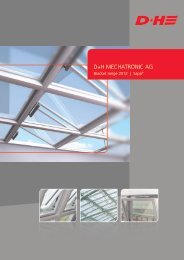
clEAr GEoMEtrIc ArEAA v= clear width (W l) × clear height (H l)A v= W l× H lH LW LAErodynAMIc frEE ArEA for nSHEVSA a= A v× cv (in roof; cv0 in vertical facade)When nSHEVs are installed in a vertical facade a wind sensitive control system is manda<strong>to</strong>ry. for this reason, theaerodynamic coefficient of discharge without side wind influence (cv0) can be measured in nSHEVs installed forfacade smoke extraction.the influence of the side wind (cv) must be taken in<strong>to</strong> account in nSHEVs for roof installation.22Section A
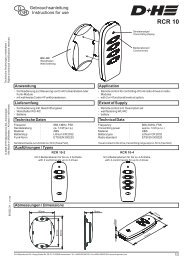
Determining the coefficient of dischargeThe determined aerodynamic coefficients of discharge are displayed on a graph. The following is an example ofthis type of graph for bot<strong>to</strong>m hung and <strong>to</strong>p hung vents opening inwards:If the ratio of width <strong>to</strong> height of the NSHEV is known, the Cv0 value in the vertical facade and the Cv value inthe roof can be read off the array of curves for the desired opening angle.Section A23
2.2. Initial inspection of fac<strong>to</strong>ry production control and the quality planThe NSHEV manufacturer must establish fac<strong>to</strong>ry production control <strong>to</strong> ensure that the NSHEV brought in<strong>to</strong> circulationexhibits the specified performance classes. This is tested by the notified test centre.The fac<strong>to</strong>ry production control must include processes and procedures <strong>to</strong> verify the manufacture of the NSHEV insuitable production steps. The production machines and the measuring and testing equipment are also examined.The manufacturer must also create a product-specific quality plan that defines the frequency with which tests areperformed on the NSHEV components or on the finished NSHEV.2.3. The EC certificate of conformityAfter all tests have been completed, the NSHEV distribu<strong>to</strong>r receives the EC certificate of conformity and is therebyauthorised <strong>to</strong> mark the NSHEVs <strong>according</strong>ly. The second and third pages of the certificate contain the productand classification characteristics.Section A25
Example EC certificate of conformity:1. CPD No.2. Type3. Certified company1. The CPD number consists of the first four numbers identifying the notified test centre. In this example, 0786stands for the VdS test centre. The first four digits are followed by the three characters CPD (ConstructionProducts Directive) and the identification number of the certified company. In this example, the sequential number50075 stands for <strong>D+H</strong> <strong>Mechatronic</strong> AG.2. The designation “RES…” indicates for what type of smoke and heat exhaust ventila<strong>to</strong>rs an EC certificate ofconformity has been issued. Our example is the roof exhaust system, i.e. a roof NSHEV. Type “FES...” stands forfacade exhaust system. Further type specifications are provided in Attachment 1 of the EC certificate of conformity.3. The certified company with full address is named here. The certified company is the distribu<strong>to</strong>r of the NSHEV;the certified company is moni<strong>to</strong>red by a notified centre and is responsible for the conformity of the NSHEV withDIN <strong>EN</strong> <strong>12101</strong>-2.26Section A
2.4. Marking an NSHEV in accordance with <strong>EN</strong> <strong>12101</strong>-2<strong>EN</strong> <strong>12101</strong>-2 defines what information the CE type plate must contain. In addition <strong>to</strong> the manufacturer informationand the number of the EC certificate of conformity, this includes the performance classes confirmed duringinitial type testing. You can obtain the CE type plate from your responsible <strong>D+H</strong> partner (see page 8).The following is a general example of a CE type plate:Dimensions of the CE label Width: 104 mm Height: 20 mm2.4.1. Description of the CE type plateThe individual entries in the first line of the type plate:1 2 3 4 5 6 71: FES Vertical facade (field of application)2: XX Profile manufacturer (must be entered)3: W CCasement width: 2,500 mm4: H CCasement height: 1,600 mm5: 45 Opening angle in degrees6: KA Drive type (in this case chain drive)7: 24 V Power supplySection A27
The entries in the middle line of the type plate:8 9 10 11 12 13 14 158: SL Snow load classification (not required for vertical facade)9: Aa Aerodynamic free opening area of the NSHEV10: Value of Aa, in this case 0.466 m 211: B 300-E Classification of resistance <strong>to</strong> heat (in this case 300°C)12: Re1000 Classification of reliability with SHEV dual function (1,000 strokes)13: WL Wind load classification14: Value of WL in Pa15: T (-10) Classification of reliability at low temperatures (in this case, -10°C)The entries in the bot<strong>to</strong>m line of the type plate:16 17 18 19 20 21 2216: CE The CE marking is a marking under EU law for specific products relating <strong>to</strong>product safety. By affixing the CE marking, the manufacturer confirms thatthe product conforms <strong>to</strong> the valid European directives.17: cPD No.18: Euro-SHEV partner (certified)19: current valid version of <strong>EN</strong> <strong>12101</strong>-2, 09/200320: unique NSHEV manufacturer number (located bot<strong>to</strong>m left on the NSHEVspecification)21: d+H logo (optional)22: calendar week/year28Section A
2.5. Declaration of ConformityIn the declaration of conformity, the manufacturer (certificate holder) declares that the product marked with theCE type plate conforms <strong>to</strong> the listed directives and standards. Following certification, it is possible <strong>to</strong> generatethe declaration of conformity for an NSHEV using the myCalc software (formerly the <strong>EN</strong>-Tool). You can obtainthe declaration of conformity from your responsible Euro-SHEV partner (see page 8).The declaration of conformity must be signed by the certified company of the listed product (signature 1) andby the owner/managing direc<strong>to</strong>r or authorised representative of the certified Euro-SHEV partner (signature 2).1st signature2nd signatureSection A29
3 Using NSHEVs in the buildingOwing <strong>to</strong> the different requirements and safety levels in European countries, no minimum value is defined in<strong>EN</strong> <strong>12101</strong>-2 for the performance classes. This has the disadvantage for planners that NSHEVs can be offered forsale on the German market that do not conform <strong>to</strong> the previous German minimum values. Particular attentionmust be paid when selecting NSHEVs.Requests for information <strong>to</strong> the Deutsches Institut für Bautechnik (DIBt), Berlin, and the planning authoritiesof the federal states have revealed that the German legislature does not intend <strong>to</strong> define minimum values inan environment of deregulation of German building regulations. The values for the performance classes whenplanning buildings may be – but do not have <strong>to</strong> be – defined by the state-level building regulations. Plannersand specialist companies will therefore have greater responsibility in the future.When selecting an NSHEV, it must be ensured that the performance specifications of the manufacturer are atleast equal <strong>to</strong> the performance specifications required by the location of the building. This will in future be theresponsibility of experts, as well as specialist planners and companies.The various requirements of the state-level building regulations in Germany are listed in the following table(further information is available at www.rwa-heute.de).Federal State<strong>Smoke</strong> <strong>ventilation</strong>when?<strong>Smoke</strong> <strong>ventilation</strong>where?<strong>Smoke</strong> <strong>ventilation</strong><strong>to</strong> what extent?Control panelswhere?Model Building Regulation(MBO)Required staircases in buildingsmore than 13 m high,or interior staircases required.At the highest point of thestaircase.Free cross sectional area of atleast 1 m².Ground floor and uppermostlanding.Baden-WuerttembergBavariaBerlinBrandenburgMore than 5 upper s<strong>to</strong>reyfloors, or interior staircasesrequiredRequired staircases in buildingsmore than 13 m high,or interior staircases required.Required staircases in buildingsmore than 13 m high,or interior staircases required.More than 5 upper s<strong>to</strong>reyfloors, or interior staircases.At the highest point.Windows may be designedas smoke vents if they arelocated at sufficient height.Exceptions may be permittedif the smoke can bevented by other means.At the highest point of thestaircase.At the highest point of thestaircase.At the highest point of thestaircase.Free cross sectional area of atleast 1 m².Free cross sectional area of atleast 1 m².Free cross sectional area of atleast 1 m².At least 5% of the basic areaor at least 1 m².Ground floor. Other controlpanels may be required.Ground floor and uppermostlanding.Ground floor and uppermostlanding.Ground floor and uppermostlanding.BremenHamburgHesseMecklenburg-WesternPomeraniaMore than 5 upper s<strong>to</strong>reyfloors, or interior staircasesrequired.Required staircases in buildingsmore than 13 m high,or interior staircases required.More than 5 upper s<strong>to</strong>reyfloors, or interior staircasesrequired.Required staircases in buildingsmore than 13 m high,or interior staircases required.At the highest point of thestaircase.At the highest point of thestaircase.At the highest point of thestaircase.At the highest point of thestaircase.Lower Saxony More than 6 floors. At the highest point of thestaircase.At least 5% of the basic areaor at least 1 m².Free cross sectional area of atleast 1 m².Free cross sectional area of atleast 1 m².Free cross sectional area of atleast 1 m².At least 5% of the basic areaor at least 1 m².Ground floor and uppermostlanding. Other control panelsmay be required.Ground floor and uppermostlanding.Ground floor and uppermostlanding.Ground floor and uppermostlanding.Ground floor and uppermostlanding. Other control panelsmay be required.30Section A
Federal State<strong>Smoke</strong> <strong>ventilation</strong>when?<strong>Smoke</strong> <strong>ventilation</strong>where?<strong>Smoke</strong> <strong>ventilation</strong><strong>to</strong> what extent?Control panelswhere?North Rhine-WestphaliaMore than 5 upper s<strong>to</strong>reyfloors, or interior staircasesrequiredAt the highest point of thestaircase.At least 5% of the basic areaor at least 1 m².Ground floor and uppermostlanding.Rhineland-PalatinateMore than 5 upper s<strong>to</strong>reyfloors, or interior staircasesrequired.At the highest point of thestaircase.At least 5% of the basic areaor at least 1 m².Ground floor and uppermostlanding. Other control panelsmay be required.SaarlandRequired staircases in buildingsmore than 13 m high,or interior staircases required.At the highest point of thestaircase.Free cross sectional area of atleast 1 m².Ground floor and uppermostlanding.SaxonyRequired staircases in buildingsmore than 13 m high,or interior staircases required.At the highest point of thestaircase.Free cross sectional area of atleast 1 m².Ground floor and uppermostlanding.Saxony-AnhaltRequired staircases in buildingsmore than 13 m high,or interior staircases required.At the highest point of thestaircase.Free cross sectional area of atleast 1 m².Ground floor and uppermostlanding.Schleswig-HolsteinRequired staircases in buildingsmore than 13 m high,or interior staircases required.At the highest point of thestaircase.Free cross sectional area of atleast 1 m².Ground floor and uppermostlanding.ThuringiaRequired staircases in buildingsmore than 13 m high,or interior staircases required.At the highest point of thestaircase.Free cross sectional area of atleast 1 m².Ground floor and uppermostlanding.* Observe the specifications of the Hessian Building Regulation (HBO)3.1. The right path <strong>to</strong> an NSHEVIn practice, further limitations must be observed when using NSHEV systems other than the specifications ofthe state-level building regulations; such limitations can be very different depending on the building project.Irrespective of the valid standards and directives, the following processing instructions must be observed:• the processing directives of profile system manufacturers• the processing directives of metal fitting suppliers• the processing directives of the glass industry• other standards and directives such as pinch protection, fall protection and driving rain impermeabilityThe Euro-SHEV partner requires additional specific information from the window manufacturer/planner beforean offer of a standard-compliant NSHEV system with valid and binding NSHEV specification can be made:Specific query with information regarding:-System-Size of window-Glass (weight)-Snow load/wind load-Size of the space <strong>to</strong> be vented-Opening angle and opening direction-Vertical facade/roof…Window manufacturer /plannerOffer with valid and bindingNSHEV specification<strong>D+H</strong> PartnerSection A31
4 Other product standards for smokeand heat extraction systemsStandards are also available or under development for testing control units and the energy supply of SHEV systems(see 4.1, 4.2 and 4.3).All components used <strong>to</strong> set up a complete SHEV system must be purchased from <strong>D+H</strong> <strong>Mechatronic</strong> AG. Pleasecontact your <strong>D+H</strong> partner (see page 8).4.1. pr<strong>EN</strong> <strong>12101</strong>-9 (control units)pr<strong>EN</strong> <strong>12101</strong>-9 describes the requirements and test methods for control units. This standard is valid for electrical,pneumatic and other systems.4.2. <strong>EN</strong> <strong>12101</strong>-10 (energy supply)<strong>EN</strong> <strong>12101</strong>-10 defines the requirements and test methods for the energy supply and was published in January2006.As part 9, this standard is also valid for electrical and pneumatic systems.After the coexistence period has expired, the energy supplies and control units for all smoke extraction methodsmust conform <strong>to</strong> standards pr<strong>EN</strong> <strong>12101</strong>-9 and <strong>EN</strong> <strong>12101</strong>-10 and a CE marking must be affixed, for example, <strong>to</strong>:• Natural smoke and heat exhaust <strong>ventilation</strong> systems (NSHEVs)• Powered exhaust <strong>ventilation</strong> systems• <strong>Smoke</strong> barriers• Pressure differential systems• ...4.3. TR <strong>12101</strong>-5: Dimensioning natural smoke and heat exhaust <strong>ventilation</strong>systemsThe current design standard DIN 18232-2 (2003) is not superseded by European TR <strong>12101</strong>-5, as this standard isonly provided for information purposes as a “Technical Report”.The reasons for this are the differences between the protection objectives of European states and the maintenanceof the high level of safety in Germany.32Section A
BCalculation aidsThis section is divided in<strong>to</strong> the following subsections:• Section 1 “Sample calculation in the roof: specification of the stroke”• Section 2 “Sample calculation in the vertical facade: specification of the stroke”Maximum aerodynamics are determined by, among other things, the maximum stroke of the drive and the maximumopening angle of the window. In addition, the aerodynamics are also influenced by a favourable widthheightratio.The sample calculations provide an overview of what calculations are required by the standard in addition <strong>to</strong> thetypical calculation of forces for NSHEVs. The calculations are performed by <strong>D+H</strong> myCalc (formerly <strong>EN</strong>-Tool) afterall the required information has been entered.1 Sample calculation in the roof: specification of thestrokeThis sample calculation is based on the following classification:• WL 2000• SL 1000• T(00)• B 300-E1.1. ObjectiveThe objective is <strong>to</strong> calculate the <strong>to</strong>tal aerodynamic smoke extraction cross section for this smoke section(A a target <strong>to</strong>tal) and <strong>to</strong> calculate the number of required windows.1.2. Known dataThe following data are known from the specifications or the cus<strong>to</strong>mer:• Profile system: xxx• Series: xx• Installation area: monopitch roof• angle of installation: 9°• Casement width (W CM): 1200 mm• Casement height (H CM): 1600 mm• Casement clearance: 80 mm• Unit height (H FRZK): 3280 mm• Clearance width ∆ w: 2 × 30 mm (series-dependent)• Clearance height ∆ h: 2 × 30 mm (series-dependent)• Type of opening and opening direction: Dual single flap 0-15°, outward• Fill: glass, 8/12/8 mm (glass thicknesses: individual pane / space between panes / individual pane)• Installation position of the drives: on the side opposite <strong>to</strong> the hinges• Drive: rack and pinion drive, the same for all windows• Stroke: 1000 mm• Required aerodynamic free opening area: A a target <strong>to</strong>tal≥ 3.00 m²Section B33
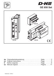
1.3. Approach1.3.1. Determining the geometric opening area A vfor a windowThe geometric opening area is calculated by multiplying the vent outer dimension width and the vent outerdimension height, in each case deducting the clearance width or height (∆ w and ∆ h):A v= clear width (RLB) × clear height (RLH)A v= (W CM– 2 ∆ w) × (H FRZK– 2 ∆ h)A v= (1200 – 60) × (3280 – 60)A v= 1140 × 3220A v= 3.67 m²1.3.2. Determining the width/height ratio of a casementThe width-height ratio is calculated from the ratio of clear width and clear height:W/H = clear width (RLB): clear height (RLH)W/H = 1 140: 3 220W/H = 0.351.3.3. Determining the opening angleThe opening angle is read off the following graph as a function of the stroke and the height. The values displayedon this graph are based on a simple sine trigonometric function. The graph is universally applicable across allsystems:Ratio of the opening angle <strong>to</strong> the height dependent on the strokeSash height Fh [mm]Stroke 800Opening angle [DEG]Stroke 300Stroke 1100Stroke 400Stroke 1200Stroke 500Stroke 1300Stroke 600 Stroke 700 Stroke 800 Stroke 900Stroke 1400Stroke 100034TeilSectionAA
In this sample calculation, an opening angle of 37° is calculated at a vent height of 1,600 mm and a stroke of1,000 mm.1.3.4. dEtErMInInG tHE coEffIcIEnt of dIScHArGE cVusing the width-height ratio determined under 1.3.2., the coefficient of discharge cv required for the next calculationcan now be read off the corresponding table for the system:At a width-height ratio of 0.35 and an opening angle of 35°, the coefficient of discharge cv is 0.46. As the openingangle of 37° calculated in 1.3.3. and the associated cv value are not yet reached, the next lowest openingangle must be applied. (the cv values can easily become worse as the width-height ratio increases and at lowopening angles from the influence of jambs and latches.)In general: the lower the width-height ratio, the better the cv value. the tables used <strong>to</strong> determine the openingangle per series are provided in the “technical Information” part of the d+H Euro-SHEV system module.1.3.5. dEtErMInInG tHE AErodynAMIc frEE oPEnInG ArEA for An nSHEVthe aerodynamic free opening area for a window/nSHEV is calculated by multiplying the geometric opening areaA vcalculated in 1.3.1. with the coefficient of discharge cv from 1.3.3.:A a= A v× cvA a= 3.67 m² × 0.46A a= 1.68 m²/nSHEV1.3.6. dEtErMInInG tHE nuMBEr of WIndoWS rEquIrEd for tHIS SMoKE SEctIonIn this sample calculation, it is assumed the windows are the same. If windows are different, this calculation mustbe repeated per window. the sum of the aerodynamic free opening area of the individual windows then providesthe value for the <strong>to</strong>tal smoke extraction area.A a target <strong>to</strong>tal: A a= number of windows required for this smoke section3.00 m²: 1.68 m² = 21.4. rESulttwo dual single flaps are required <strong>to</strong> achieve the aerodynamic <strong>to</strong>tal smoke extraction cross section for this smokesection at a stroke of 1,000 mm and a unit size of 1,200 × 3,280 mm.Section B35
2 SAMPlE cAlculAtIon In tHE VErtIcAl fAcAdE: SPEcIfIcAtIonof tHE StroKEthis sample calculation is based on the following classification:• WL 3000• SL 0• T(00)• B 300-E2.1. oBJEctIVEthe objective is <strong>to</strong> calculate the <strong>to</strong>tal aerodynamic smoke extraction cross section for this smoke section(A a target <strong>to</strong>tal) and <strong>to</strong> calculate the number of required windows.2.2. KnoWn dAtAthe following data are known from the specifications or the cus<strong>to</strong>mer:• Profile system: xxx• Series: xx• Installation area: vertical facade• Casement width (W cM): 1200 mm• Casement height (H cM): 1600 mm• Clearance width ∆ w: 2 × 30 mm (series-dependent)• Clearance height ∆ h: 2 × 30 mm (series-dependent)• Type of opening and opening direction: Bot<strong>to</strong>m hung vent, inward• Fill: glass, 6/12/6 mm (glass thicknesses: individual pane / space between panes / individual pane)• Installation position of the drives: on the side opposite <strong>to</strong> the hinges• Drive: chain drive, the same for all windows• Stroke: 1000 mm• Required aerodynamic free opening area: A a target <strong>to</strong>tal≥ 3.50 m²2.3. APProAcH2.3.1. dEtErMInInG tHE GEoMEtrIc oPEnInG ArEA A Vfor A WIndoWthe geometric opening area is calculated by multiplying the vent outer dimension width and the vent outerdimension height, in each case deducting the clearance width or height (∆ w and ∆ h):A v= clear width (rlB) × clear height (rlH)A v= (W cM– 2 ∆ w) × (H cM– 2 ∆ h)A v= (1200 – 60) × (1600 – 60)A v= 1140 × 1540A v= 1.76 m²36
2.3.2. dEtErMInInG tHE WIdtH/HEIGHt rAtIo of A cASEMEntthe width-height ratio is calculated from the ratio of clear width and clear height:W/H = clear width (rlB): clear height (rlH)W/H = (1200 - 60) : (1600 – 60)W/H = 1 140 : 1 540W/H = 0.74 → W/H < 1.002.3.3. dEtErMInInG tHE oPEnInG AnGlEthe opening angle is read off the following graph as a function of the stroke and the height. the values displayedon this graph are based on a simple sine trigonometric function. the graph is universally applicable across allsystems:Ratio of the opening angle <strong>to</strong> the height dependent on the strokeSash height Fh [mm]Stroke 800Opening angle [DEG]Stroke 300Stroke 1100Stroke 400Stroke 1200Stroke 500Stroke 1300Stroke 600 Stroke 700 Stroke 800 Stroke 900Stroke 1400Stroke 1000In this sample calculation, an opening angle of 37° is calculated at a vent height of 1,600 mm and a stroke ofTeil A1,000 mm.2.3.4. dEtErMInInG tHE coEffIcIEnt of dIScHArGE cV0using the width-height ratio determined under 2.3.2., the coefficient of discharge cv0 required for the nextcalculation can now be read off the corresponding table for the system:Openingasinwardsbot<strong>to</strong>m/<strong>to</strong>phungFrame cleardimensions overlapWWWWOpening angle°At a width-height ratio of 0.74 and an opening angle of 35°, the coefficient of discharge cv0 is 0.40. As theopening angle of 37° calculated in 2.3.3. and the associated cv0 value are not yet reached, the next lowestSection B37
opening angle must be applied. (The Cv0 values can easily become worse as the width-height ratio increases andat low opening angles from the influence of jambs and latches.)In general: the lower the width-height ratio, the better the Cv0 value. The tables used <strong>to</strong> determine the openingangle per series are provided in the “Technical Information” section of the <strong>D+H</strong> Euro-SHEV system module.2.3.5. Determining the aerodynamic free opening area for an NSHEVThe aerodynamic free opening area for a window/NSHEV is calculated by multiplying the geometric opening areaA vcalculated in 2.3.1. with the coefficient of discharge Cv0 from 2.3.3.:A a= A v× Cv0A a= 1.76 m² × 0.40A a= 0.70 m²/NSHEV2.3.6. Determining the number of windows required for this smoke sectionIn this sample calculation, it is assumed the windows are the same. If windows are different, this calculation mustbe repeated per window. The sum of the aerodynamic free opening area of the individual windows then providesthe value for the <strong>to</strong>tal smoke extraction area.A a target <strong>to</strong>tal: A a= number of windows required for this smoke section3.50 m²: 0.70 m² = 52.4. ResultFive windows are required <strong>to</strong> achieve the aerodynamic <strong>to</strong>tal smoke extraction cross section for this smoke sectionat a stroke of 1,000 mm and a vent size of 1,200 × 1,600 mm.38Section B
CInformation about <strong>D+H</strong> drives and bracketsThis section provides an overview of the general installation options for <strong>D+H</strong> drives in vertical facades and skylights.<strong>D+H</strong> <strong>Mechatronic</strong> AG supplies a number of different chain, linear and lock drives. Specific product informationis provided in the <strong>D+H</strong> product information folder and on the internet at www.dh-partner.com/produkte/antriebe.html.Section C39
1 Installation positions of <strong>D+H</strong> drivesThe possible Installation positions for <strong>D+H</strong> drives and locking mechanisms are outlined below for the differenttypes of window, fields of application and opening directions.The specific installation options for <strong>D+H</strong> drives for any profile system are listed in the <strong>D+H</strong> Euro-SHEV system module.1.1. Installation positions for drives on windows in the vertical facadeAll diagrams are from the interior:NSHEV in the vertical facadeType of openingDriveOpening directionLock drive (optional)InwardsOutwardTurn hingeSide opposite <strong>to</strong> the hingesOne driveTop hung vent Bot<strong>to</strong>m hung ventSide opposite <strong>to</strong> the hingesTwo drivesSide mountedTwo drivesSide opposite <strong>to</strong> the hingesOne driveSide opposite <strong>to</strong> the hingesTwo drivesSide mountedTwo drives40Section C
NSHEV in the vertical facadeType of openingDriveOpening directionLock drive (optional)InwardsOutwardTurn hingeSide opposite <strong>to</strong> the hingesOne driveSide hung ventSide opposite <strong>to</strong> the hingesTwo drivesSide mountedTwo drivesTop-hunglowering ventSide opposite <strong>to</strong> the hingesOne driveParallelopening ventTwo drivesThe specific installation options for <strong>D+H</strong> drives for any profile system are listed in the <strong>D+H</strong> Euro-SHEV systemmodule.Section C41
1.2. Installation positions for drives on windows in the skylight areaAll diagrams are from the interior:NSHEV in skylightsType of openingOpening directionDriveOutwardTurn hingeBot<strong>to</strong>m hung ventAngle of installation 25-60°Side opposite <strong>to</strong> the hingesOne driveSide opposite <strong>to</strong> the hingesTwo or more drivesSide mountedTwo drivesSide opposite <strong>to</strong> the hingesTwo drivesDual single flapAngle of installation 0-30°Side opposite <strong>to</strong> the hingesFour or more drivesSide mountedFour drivesWith all possibleinstallation positions in gable roofThe specific installation options for <strong>D+H</strong> drives for any profile system are listed in the <strong>D+H</strong> Euro-SHEV systemmodule.42Section C
2 <strong>D+H</strong> bracket sets<strong>D+H</strong> <strong>Mechatronic</strong> AG provides the right bracket sets for each drive for the different types of installation on differentprofile systems. The bracket sets include sash brackets and frame brackets. The choice of bracket setsdepends on the application.Suitable bracket sets for the drive series are available on the product pages online.The bracket sets are listed in the sales information.<strong>D+H</strong> <strong>Mechatronic</strong> AG also provides system-specific bracket sets (see the <strong>D+H</strong> Euro-SHEV system modules as well).Section C43
DEuro-SHEVs: Working materialsThis section describes the aids and descriptions <strong>to</strong> identify an NSHEV. <strong>D+H</strong> <strong>Mechatronic</strong> AG provides extensiveworking materials for this purpose via the my<strong>D+H</strong> website.You can access the login page for my<strong>D+H</strong> via the <strong>D+H</strong> <strong>Mechatronic</strong> AG website www.dh-partner.com/service.html.If you are interested in cooperation with <strong>D+H</strong> <strong>Mechatronic</strong> AG, we would be delighted <strong>to</strong> send you access data.You will receive general and specific information about my<strong>D+H</strong> (infomy<strong>D+H</strong>), how <strong>to</strong> log in, how <strong>to</strong> create anNSHEV specification and how <strong>to</strong> print a CE type plate in PDF format via my<strong>D+H</strong>.44Section D
ETerms and abbreviations1 Explanation of terms in accordance with <strong>EN</strong> <strong>12101</strong>-2Exhaust ventila<strong>to</strong>rDevice <strong>to</strong> exhaust gases from a building in case of fire.Aerodynamic free areaGeometric opening area multiplied by the coefficient of discharge.Aerodynamic efficiencyAnother term for coefficient of discharge.<strong>Smoke</strong> and heat exhaust system<strong>Smoke</strong> and heat control system that exhausts smoke and heat from a fire in aconstruction works or part of a construction works.<strong>Smoke</strong> and heat control systemArrangement of components in a construction works <strong>to</strong> limit the effects of smoke andheat from a fire.Activation deviceDevice that activates the opening mechanism of the components (e.g. a fire flap or a natural smoke and heatexhaust ventila<strong>to</strong>r) after being triggered by a fire detection element.Au<strong>to</strong>matic natural smoke and heat exhaust ventila<strong>to</strong>rNatural smoke and heat exhaust ventila<strong>to</strong>r which opens au<strong>to</strong>matically after the outbreak of fire. Au<strong>to</strong>maticsmoke and heat exhaust ventila<strong>to</strong>rs can also be fitted with manual actuation or a manual activation device.Au<strong>to</strong>matic activationActivation of the opening mechanism by a fire detection element without human intervention.Range of natural smoke and heat exhaust ventila<strong>to</strong>rsNatural smoke and heat exhaust ventila<strong>to</strong>rs of various sizes having the same method of construction (identicalnumber of hinges on a louvre or flap, identical material and thickness, etc.) and identical number and type ofopening devices.Section E45
Fire detection elementsElements that respond with a change in state when a fire parameter occurs or changes.Width-height ratioRatio of width <strong>to</strong> height in bot<strong>to</strong>m hung, <strong>to</strong>p hung, side-hung and dormer windows.CE markingBy affixing the CE marking, the manufacturer confirms that the product conforms <strong>to</strong> the applicable EC directives.For further information, go <strong>to</strong>: http://www.vdi-nachrichten.com/ce-richtlinien/basics/index.asp.Coefficient of discharge (Cv) (with side wind influence)Ratio of actual flow rate, measured under specified conditions, <strong>to</strong> the theoretical flow rate through the naturalsmoke and heat exhaust ventila<strong>to</strong>r. The coefficient of discharge takes in<strong>to</strong> account any obstructions in the naturalsmoke and heat exhaust ventila<strong>to</strong>r such as controls, louvres, vanes and the influence of side winds.Coefficient of discharge (Cv0) (without side wind influence)Ratio of actual flow rate, measured under specified conditions, <strong>to</strong> the theoretical flow rate through the naturalsmoke and heat exhaust ventila<strong>to</strong>r. The coefficient of discharge takes in<strong>to</strong> account any obstructions in the naturalsmoke and heat exhaust ventila<strong>to</strong>r such as controls, louvres, and vanes without the influence of side winds.Fire open positionTarget opening position of smoke and heat exhaust ventila<strong>to</strong>rs <strong>to</strong> be achieved and sustained while venting smokeand heat.Geometric area (Av)Opening area of a natural smoke and heat exhaust ventila<strong>to</strong>r. Controls, louvres and other obstructions are nottaken in<strong>to</strong> account.Geometric free areaSmallest cross sectional area of a ventila<strong>to</strong>r through which flow occurs.Manual activationInitiation of the operation of a smoke and heat exhaust ventila<strong>to</strong>r by a human action (e.g. by pressing a but<strong>to</strong>nor pulling a handle).46Section E
Aspect ratioRatio of length <strong>to</strong> width in side-hung windows.Natural <strong>ventilation</strong>Ventilation caused by buoyancy forces due <strong>to</strong> differences in the density of the gases because of temperaturedifferences.Natural smoke and heat exhaust ventila<strong>to</strong>r (NSHEV)Device <strong>to</strong> exhaust smoke and hot gases out of a construction works in case of fire.Dual purpose natural smoke and heat exhaust ventila<strong>to</strong>rNatural smoke and heat exhaust ventila<strong>to</strong>r that can also be used for day <strong>to</strong> day <strong>ventilation</strong>.Opening timePeriod (≤ 60 seconds) between the smoke and heat exhaust ventila<strong>to</strong>r receiving the signal andreaching the functional position (opening position) in case of fire.<strong>Smoke</strong> and heat exhaust ventila<strong>to</strong>r (SHEV)Consists of components selected <strong>to</strong> exhaust smoke and heat in order <strong>to</strong> generate a stable layer of warm gasesabove cooler and cleaner air.Thermal activation elementTemperature-sensitive activation deviceManually opened smoke and heat exhaust ventila<strong>to</strong>r<strong>Smoke</strong> and heat exhaust ventila<strong>to</strong>r that can only be opened manually.Wind sensitive control systemControl system designed <strong>to</strong> control two or more banks of natural smoke and heat exhaust ventila<strong>to</strong>rs in differentbuilding side walls so that only the NSHEVs not subject <strong>to</strong> positive wind pressures open in case of fire.Section E47
2 Symbols and abbreviationsThe following mathematical and physical parameters represented by their symbols and units apply <strong>to</strong> the applicationof standard <strong>EN</strong> <strong>12101</strong>-2.Symbol/Parameter / descriptionUnitabbreviation- -Aa Aerodynamic free area m²A vGeometric opening area of the natural smoke and heat exhaust ventila<strong>to</strong>r m²W CM Casement width (maximum sash dimension) mmH CM Casement height (maximum sash dimension) mmB 300 Classification of the resistance <strong>to</strong> heat at 300°C °CW/HFrame clear width <strong>to</strong> frame clear height quotient (RLB/RLH)CvCoefficient of discharge with side wind influenceCv0Coefficient of discharge without side wind influenceEClassification of the reaction <strong>to</strong> fire of materials in accordance with<strong>EN</strong> 1305-1FMVent mountingg Vent weight N/m²KAChain driveLe 10 000Classification of the <strong>ventilation</strong> function (10,000 times open and close <strong>to</strong>/from the <strong>ventilation</strong> comfort position)MBCentre of hingeMVCentre locknNumber of NSHEV elementsNSHEVNatural smoke and heat exhaust ventila<strong>to</strong>rPd Wind stagnation pressure PaRAB Frame outer dimension width mmRAH Frame outer dimension height mmRe 1000Classification of reliability (1,000 times fully open smoke vent position)RLB Frame clear dimension width mmRLH Frame clear dimension height mmRMFrame mountingSL Snow load classification PaSoloSingle driveT Temperature °CT(00) Functional test classification at above 0°C (room temperature) TDTDTandem drive48Section E
Symbol/abbreviationParameter / descriptionUnitV Side wind velocity m/sVHLocking mo<strong>to</strong>rVMConcealed mountingWL Wind load classification PaZARack and pinion drive∆ w W CM- clear width (RLB) mm∆ h H CM- clear height (RLH) mmα Opening angle of the NSHEV DegreesΘ (Theta) Angle of installation of natural smoke and heat exhaust ventila<strong>to</strong>rs on a roof DegreesSection E49
WWW.dH-PArtnEr.coM©2013 d+H <strong>Mechatronic</strong> AG, Ammersbek 99.701.74, 1.0/01/13d+H <strong>Mechatronic</strong> AGGeorg-Sasse-Strasse 28-32d-22949 AmmersbekGermanytel.: +49 40 60565 0fax: +49 40 60565 222E-mail: info@dh-partner.com