YS05S16 DC-DC Converter Data Sheet - Power-One
YS05S16 DC-DC Converter Data Sheet - Power-One
YS05S16 DC-DC Converter Data Sheet - Power-One

Create successful ePaper yourself
Turn your PDF publications into a flip-book with our unique Google optimized e-Paper software.
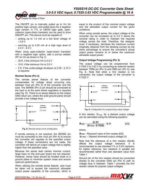
<strong>YS05S16</strong> <strong>DC</strong>-<strong>DC</strong> <strong>Converter</strong> <strong>Data</strong> <strong>Sheet</strong>3.0-5.5 V<strong>DC</strong> Input; 0.7525-3.63 V<strong>DC</strong> Programmable @ 16 AThe ON/OFF pin is internally pulled up to Vin forpositive logic version, and pulled down for a negativelogic version. A TTL or CMOS logic gate, opencollector(open-drain) transistor can be used to driveON/OFF pin. This device must be capable of:– sinking up to 1.2 mA at a low level voltage of 0.8 V– sourcing up to 0.25 mA at a high logic level of2.3 V - 5.5 V.When using open-collector (open-drain) transistorwith a negative logic option, add a pull-up resistor(R*) to Vin as shown in Fig. C:– 20 K, if the minimum Vin is 4.5 V– 10 K, if the minimum Vin is 3.0 V– 5 K, if the undervoltage shutdown at 2.05 - 2.15 Vis required.Remote Sense (Pin 2)The remote sense feature of the convertercompensates for voltage drops occurring onlybetween Vout pin (Pin 4) of the converter and theload. The SENSE (Pin 2) pin should be connected atthe load or at the point where regulation is required(see Fig. D). There is no sense feature on the outputGND return pin, where the solid ground plane shouldprovide a low voltage drop.equal to the product of the nominal output voltageand the allowable output current for the givenconditions.When using remote sense, the output voltage at theconverter can be increased up to 0.5 V above thenominal rating in order to maintain the requiredvoltage across the load. Therefore, the designermust, if necessary, decrease the maximum current(originally obtained from the derating curves) by thesame percentage to ensure the converter’s actualoutput power remains at or below the maximumallowable output power.Output Voltage Programming (Pin 3)The output voltage can be programmed from0.7525 V to 3.63 V by connecting an external resistorbetween TRIM pin (Pin 3) and GND pin (Pin 5); seeFig. E. Note that when a trim resistor is notconnected, the output voltage of the converter is0.7525 V.VinVinON/OFFGNDY-Series<strong>Converter</strong>(Top View)SENSEVoutTRIMRloadRTRIMVinVinON/OFFGNDY-Series<strong>Converter</strong>(Top View)SENSEVoutTRIMFig. D: Remote sense circuit configuration.RwRwRloadIf remote sensing is not required, the SENSE pinmust be connected to the Vout pin (Pin 4) to ensurethe converter will regulate at the specified outputvoltage. If these connections are not made, theconverter will deliver an output voltage that is slightlyhigher than the specified value.Because the sense lead carries minimal current,large trace on the end-user board are not required.However, sense trace should be located close to aground plane to minimize system noise and ensureoptimum performance.When utilizing the remote sense feature, care mustbe taken not to exceed the maximum allowableoutput power capability of the converter, which isFig. E: Configuration for programming output voltage.A trim resistor, R TRIM , for a desired output voltagecan be calculated using the following equation:21.07RTRIM 5.11[kΩ](VO-REQ- 0.7525)where,RTRIM Required value of trim resistor [kΩ]VOREQ Desired (trimmed) output voltage [V]Note that the tolerance of a trim resistor directlyaffects the output voltage tolerance. It isrecommended to use standard 1% or 0.5% resistors;for tighter tolerance, two resistors in parallel arerecommended rather than one standard value fromTable 1.Ground pin of the trim resistor should be connecteddirectly to the converter GND pin (Pin 5) with novoltage drop in between. Table 1 provides the trimresistor values for popular output voltages.MCD10205 Rev. 1.0, 24-Jun-10 Page 6 of 25 www.power-one.com