TS93 GSR EMF PT
TS93 GSR EMF PT
TS93 GSR EMF PT

You also want an ePaper? Increase the reach of your titles
YUMPU automatically turns print PDFs into web optimized ePapers that Google loves.
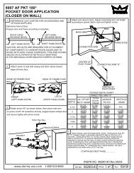
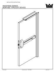
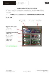
<strong>TS93</strong> <strong>GSR</strong>/<strong>EMF</strong> <strong>PT</strong>INSTRUCTIONSATTENTION!!!Before you begin, determine installation type (RIGHT HAND ACTIVE OR INACTIVE).Door coordinator suitable for door from 59” to 98” in width. Inactive door width in the case of unequal doorsis a 23” minimum. Also, you will need the tools listed below.LEFT HAND INACTIVERIGHT HAND ACTIVERIGHT HAND INACTIVELEFT HAND ACTIVETool List:Tape Measure #10-32 Tap & Holder No. 21 (.159”) & 1/8” Drill Bits and Drill HacksawCenter Punch & Hammer 1/2” Box Wrench #2 Cross-Point Screw Driver3/16” Slotted Driver 10” Adjustable Wrench 2.5mm, 3mm & 5mm Hex Wrench (supplied)INS NO: 08281031 PAGE: 1 of 11 REV: 09/11
<strong>TS93</strong> <strong>GSR</strong> <strong>EMF</strong> <strong>PT</strong>CAUTION: Sex nuts are required for attachment of components to unreinforced, wood or plastic faced compositetype fire doors, unless an alternative method is identified in the individual door manufacture’s listings.Make sure door efficiently operates prior to installing the closer. When Installing main arm, observe directionsclosely. .1Prepare door and frame using the template (TMP No. 08281030) provided in the back of the instructions.Attach both closer mounting plates to the doors using 8 flat head screws, 4 ea. Arrows on plate pointing upwards.Attach left hand mounting angle to the frame with 3 flat head screws.Attach right hand mounting angle to the frame with 3 flat head screws.2211Left HandRight Hand2Cut middle filler angle as shown belowAttach Middle Filler Angle with 2 flat head screws.Parts List:No. Description1) Closer Mounting Plate2) Track Mounting Angle3) Middle Filler Angle (cut)4) Wood Door Screws5) #10-32 Metal Door ScrewsQty2211616Wood Door Screw543Cut#10-32 Metal Door ScrewWhen cutting filler angle be sure to plan for theconduit hole 5/16 DIA [8mm].INS NO: 08281031 PAGE: 2 of 11 REV: 09/11
<strong>TS93</strong> <strong>GSR</strong> <strong>EMF</strong> <strong>PT</strong>3Attach active track assembly with two M5 flat head machine screws, be sure to insert the end cap as shown below.Attach the Inactive Track Assembly with two M5 Flat Head Machine Screws, be sure to insert the end cap. The following describesthe process for a left-handed active leaf. The procedure for right-hand active leaf should be adaptedaccordingly.3344Left Hand Active Door12Right Hand Inactive DoorParts List:No. Description1) Active Track Assembly2) Inactive Track Assembly3) M5 Metal Track Screws4) Plastic End Cap5) <strong>TS93</strong> Closer6) M5 Closer Mounting ScrewsQty1142284Attach closers with eight (8) M5 flat head machine screws.M5 Metal Track ScrewsM5 Closer Mounting Screws3656INS NO: 08281031 PAGE: 3 of 11 REV: 09/10
<strong>TS93</strong> <strong>GSR</strong> <strong>EMF</strong> <strong>PT</strong>5Place wrench on bottom of pinion square and rotate approximately 5 degrees as shown. With the main arm parallel to the door.Place the main arm hub on to the top pinion square and fasten securely with pinion screw.Hex KeyM6 Socket Head ScrewTrack Arm2Left HandRight Hand6 Attach arm to slide shoe. Continue to rotate arm until parallel totrack (door closed). Insert screw and tighten securely.4Slide Shoulder BoltParts List:No. Description1) Hex Key2) M6 Socket Head Screw3) Track Arm4) Slide Shoulder BoltQty1222M6 Socket Head ScrewSlide Shoulder Bolt42Note: Depress trigger dial, (see page 5) to allow the active slide shoeto move freely. Locking pin may fall out, (see page 6) and can be discardedafter installation is complete.INS NO: 08281031 PAGE: 4 of 11 REV: 09/10
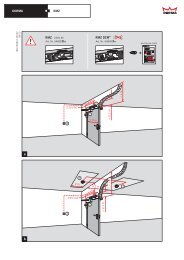
<strong>TS93</strong> <strong>GSR</strong> <strong>EMF</strong> <strong>PT</strong>7Close both door leaves. Press lever with roller against the door (A)and tighten the hex screw (B). Remove Alignment screw (C).7CDOORDOOR7BSIDE VIEWROLLER7A8Mark and cut the length of the connecting channel as shown. In doing so, it will ensure that the plastic guide element is pushed upagainst the slide shoe, and the trigger dial has been fully turned in (clockwise). Cut the connecting channel at the cut mark. Removeburrs and set the connecting channel in place by opening both doors leaves. Move arm with roller to maximum degree, in the directionof the open door leaf. Insert the channel into the trigger dial of the active leaf and then place into the plastic guide of the inactive leaf.Trigger DialPlasticGuideSide view ofConnecting ChannelINS NO: 08281031 PAGE: 5 of 11 REV: 09/10
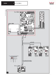
<strong>TS93</strong> <strong>GSR</strong> <strong>EMF</strong> <strong>PT</strong>9Close both door leaves. Unwind the trigger dial (counter clockwise)by hand until the pin drops out. The active door will starts to close.Ensure that the clamping plate remains perpendicular (90 deg) tothe clamping rod. Tighten set screw to secure trigger dial.10The clamping rod will only operate smoothly if the clampingplate has been properly adjusted. Only then will the activeleaf swing freely with the inactive leaf closed.Pin can be discarded once thesystem has been installed.WIRINGDIAGRAM10 WIRINGAttach plug-in side of wire harness to 4 pin terminal block on active track assembly.Attach wire to hold open screw terminal on inactive track.Make sure power is off while making connection. Connect to incoming24 VDC power supply. Connect plug-in side of incomingpower wire harness to final 2 terminals of 4 pin terminal block onactive track assembly.INS NO: 08281031 PAGE: 6 of 11 REV: 09/10
<strong>TS93</strong> <strong>GSR</strong> <strong>EMF</strong> <strong>PT</strong>11Adjust sweep (S), latch (L), backcheck (BC) and delay action (DA) valves.LBCSCAUTION: DO NOT REMOVE VALVE!!!Adjust Sweep (S), Latch (L) valves.DECREASE SPEEDINCREASE SPEEDAdjust Backcheck (BC) and delay action (DA) valves.DADECREASEINCREASE(BC INTENSITY)(DA TIME)S - Sweep speed from 70 deg opening to close (0 deg).L - Latch speed from approximately 7 deg to close (increase speed only).BC - Backcheck cushion effect (IMPORTANT Do NOT close valve completely)!DA - Delay speed from approximately 135 deg to 70 deg.12Adjust spring power (IMPORTANT: Adjust clockwise according to chart).Barrier free openings should be adjusted to use the minimum closing force required toclose and latch the door.INS NO: 08281031 PAGE: 7 of 11 REV: 09/10
<strong>TS93</strong> <strong>GSR</strong> <strong>EMF</strong> <strong>PT</strong>13Setting the hold open point. Open the door leaf ` until engaged in hold open. If another degree of hold open is desired, loosenadjustment screws. Slide the electric hold open assembly in the appropriate direction for an increased or decreased degree of holdopen and retighten adjustment screws.GREATERDOORANGLE.INS NO: 08281031 PAGE: 8 of 11 REV: 09/10
<strong>TS93</strong> <strong>GSR</strong> <strong>EMF</strong> <strong>PT</strong>14<strong>GSR</strong>/<strong>EMF</strong> - ACTIVE DOOR HOLD OPEN ONLY or ACTIVE & INACTIVE DOOR HOLD OPEN TOGETHERIncorporates an electric hold open device in both leaves. This enables both leaves to be held open when inactive leaf is placed in the preselectedhold open position and also enables the active leaf to be held open independently when the inactive leaf is in the closed position.Both doors will close in sequence (inactive first) from any point upon signal from the fire alarm system or when an electrical current is interrupted.The doors will close from any point upon signal from the fire alarm system or when an electrical current is interrupted.Setting the release force. Adjust the release force to suit the door width and size of the door.Note: If the release force is set too high, damage might occur to door hinges or the <strong>GSR</strong> system.DECREASE FORCEINCREASE FORCEINCREASE FORCEDECREASE FORCEINS NO: 08281031 PAGE: 9 of 11 REV: 09/10
<strong>TS93</strong> <strong>GSR</strong> <strong>EMF</strong> <strong>PT</strong>15INSTALL END CAP TRIM AND COVERSClip on end cap trims.Break out marked recess in the active and inactive leaf track cover and clip cover into positionACTIVE LEAF COVERINACTIVE LEAF COVEREnd captrim16INSTALL CENTER COVER AND CENTER CAPSDetermine the required length of centre cover and saw tosize. Clip on cover. Break out marked recess on plastictrim for inactive leaf. Fit plastic jointing elements.JOINTINGELEMENTSCENTER COVERJOINTINGELEMENTSINS NO: 08281031 PAGE: 10 of 11 REV: 09/10
<strong>TS93</strong> <strong>GSR</strong> <strong>EMF</strong> <strong>PT</strong>15INSTALL CLOSER COVERSInstall closer end covers and closer covers.16Slide end covers over closer body end caps.Remove tab that aligns with arm hub. Slidecover onto plate.INSTALL CARRY BARA carry bar must be installed to insure that the active door is opened far enough for the inactive door to close.DORMA carry bar MK-398 (3’-6” and wider door) is required! Installation instructions are included with the carry bar.Secure with locking screw.16FINAL INSTALLATION AND TEST1. After installation is complete, check all connections.2. Open doors to desired position.3. For <strong>EMF</strong> activate system in alarm so the electromagnets release, and the doors close.Normal Operation - The unit’s electromagnet will be energized by the alarm system, by applying 24VDC power supply.Fire Alarm - When the alarm activates, current will automatically be cut, causing the electromagnets to release, allowing the doors toclose.IMPORTANT: The unit must be tested after installation, by the end user, to be certain the door closer unit functions properly when thealarm system is activated. The entire system must be tested periodically after the initial installation test, in conjunction with the testing ofthe fire alarm system. The end user is responsible for maintaining the door closing system.INS NO: 08281031 PAGE:11 of 11 REV: 09/10