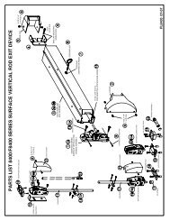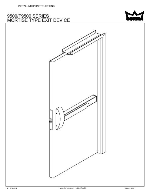
MORTISE TYPE EXIT DEVICE 9500/F9500 SERIES
MORTISE TYPE EXIT DEVICE 9500/F9500 SERIES
MORTISE TYPE EXIT DEVICE 9500/F9500 SERIES

Create successful ePaper yourself
Turn your PDF publications into a flip-book with our unique Google optimized e-Paper software.
INSTALLATION INSTRUCTIONS<strong>9500</strong>/F<strong>9500</strong> <strong>SERIES</strong><strong>MORTISE</strong> <strong>TYPE</strong> <strong>EXIT</strong> <strong>DEVICE</strong>1135-29 www.dorma-usa.com 1-800-523-8483I<strong>9500</strong>-10 9/07
HANDINGRHRLHRRHR LHRRHRLHRRHR LHRTYPICAL INSTALLATIONS<strong>9500</strong>SeriesDevice<strong>9500</strong>SeriesDevice9400SeriesDevice<strong>9500</strong>SeriesDevice9100SeriesDeviceAll Screws Are Phillips HeadF.H.P.T.S.R.H.P.T.S.R.H.P.M.S.R.H.P.M.S.F.H.P.M.S.O.H.P.M.S.SCREW CHARTFlat Head Phillips Tapping ScrewRound Head Phillips Tapping ScrewRound Head Phillips Machine ScrewRound Head Phillips Machine Screw x Thru BoltFlat Head Phillips Machine ScrewOval Head Phillips Machine Screw2
DOOR & FRAME PREPANSI 115.1 STANDARD <strong>MORTISE</strong> LOCK DOOR & FRAME PREP.UNIVERSAL OR SQUARE EDGELOCK SUPPORTBY DOOR MFR.3 3/4"(95 mm)15/64"(6 mm)PLASTER GUARDBY FRAME MFR.27/32"(21 mm)2 3/4" BACKSET(70 mm)COMMOM LC OFLOCK AND STRIKE3/32"(2 mm)1" MIN.(32 mm)1 1/4" MIN.(32 mm)4 1/2" MAX. LOCK CASE DEPTH(114 mm)3/4" MAX.(19 mm)12-24 TAP3/8"(10 mm)5/8"(16 mm)3/4" MAX.(19 mm)5/16"(8 mm)SUPPORTABOUTLC _ + 1" (25 mm)3/8"(10 mm)LOCK SUPPORTBY DOOR MFR.LCOF LOCK5/8" DIA.(16 mm)(OUTSIDEFACE ONLY)1" (25 mm) x 1 5/8" (41 mm)CUT OUT (INSIDE FACE ONLY)3 3/4"(95 mm)LCOF <strong>DEVICE</strong>& STRIKE3/8"(10 mm)2 3/16"(56 mm)15/64"(6 mm)4"(102 mm)DOOR PREP.6 1/2" MIN.(165 mm)1 1/4" MIN.(32 mm)1 3/4"(44 mm)7 1/4"(184 mm)8"(203 mm)3/8"(10 mm)3/8"(10 mm)CUTOUT INREINFORCEMENT4 7/8"(124 mm)3 3/8"(86 mm)1/2"(13 mm)1 1/16" MIN.(27 mm)3/8"(10 mm)40 5/16"(1024 mm)9/16"(14 mm)1 1/4" MIN.(32 mm)FRAME PREP.3/8"(10 mm)3 1/2"(89 mm)4 1/8"(105 mm)LCOFSTRIKEFINISHED FLOOR27/32"(21 mm)1/8" (3 mm) IN 2" (51 mm) BEVEL2 3/4" BACKSET(70 mm)4 1/2" MAX. LOCK CASE DEPTH(114 mm)BEVELED EDGE3
5Refer to carton label for model and trim number prior to drilling.Refer to Template T<strong>9500</strong>, located at rear of instruction bookletfor specific hole locations, drill size and screw sizes.1 3/4" - 2 1/4"(44-57 mm)1 1/2"(38 mm)HORIZONTALREF. LINENOTE: Holes must be parrellon opposite side of door.b7 1/2"(191 mm)25" - 48"(635-1219 mm)bVERTICALREF. LINEa6Mortise lock installationeInstall mortise cylinder thru trim and thread intolock body. Loosen cylinder retaining screw priorthru front face of lock body. Once cylinder is installedtighten retaining screw to secure cylinder.Due to cylinders being different length's the cylindermay have to be backed out a bit so cam does notinterfere with rear of lock body case. Also, if dooris not reinforced properly or screws of device aretightened to tight cylinder and lockbody mayhave interference with cam.aInstall mortise lock in door.cInstall face plate withscrews supplied.b12-24 Combintaion screwsdInstall strike in framewith screws supplied.6
7Chassis installation. If using GK9000, install shims at this time.3/8" DIA.(10 mm)12-24 Tap#12 x 1 1/4" R.H.P.T.S.a1 (Wood)(No Trim)3/8" DIA.(10 mm)12-24 x 1 1/4" R.H.P.M.S.a2 (Metal)(No Trim)3/8" DIA.(10 mm)12-24 x 1 1/4" R.H.P.M.S.a3 (Thru Bolts)(Wood or Metal)(No Trim)12-24 x 1 1/4" R.H.P.M.S.12-24 x 1 1/4" R.H.P.M.S.a4 ("Y" Trim)a5 ( "V" & "T" Trim)8Cutting touch bar to length"X"a1 13/16" (46 mm)SIZE A:Will fit 48" (1219 mm) door opening without cutting.Can be cut to fit a 34" (864 mm) minimum door opening.SIZE B:Will fit 36" (914 mm) door opening without cutting.Can be cut to fit a 28" (711 mm) minimum door opening.SIZE C:Will fit 36" (914 mm) door opening without cutting.Can be cut to fit a 25" (635 mm) minimum door opening.I M P O R T A N Tb"L" = "X" - 2 1/2" (64 mm)cNOTE: Use caution when cuttingtouchbar to size on units with "ES","MS", "BPA", "BPAR", "LM", "MD" or"DWA" options. "DO NOT CUT WIRES.""L""L"7
9Installation of touch bar to chassis8-32 x 3/8" P.H.P.M.S.NOTE:Chassis screws areshipped in chassisassembly.a1NOTE:For optional "Filler" installationssee "Options" pages 11 & 12 at rear.a28-32 x 3/8" P.H.P.M.S.10Standard installation of end cap mounting bracket*NOTE:An additional screw may beinstalled if door is warped orbowed. (Not supplied)*bcac1/8" (3 mm) Drill 1" (25 mm) Deep (Wood)No. 14 Drill - 12-24 Tap (Metal)3/8" (9 mm) Dia. (Thru bolts)OPTIONAL INSTALLATIONSADDITIONAL HOLE REQUIRED:b1aES(Electric Latch Retraction)MS(Micro Switch)5/16" DIA. (8 mm) LM(Latch Monitor)MD (Magnetic Dogging)DWA(Direct Wired Alarm)See "OPTIONS" pages foradditional information.8
11Adjustment of mortise lock and chassis assemblyBell crankGuard boltLatch boltAdjusting screwAdjusting armLoosen screw in adjusting arm (Do not remove). With bellcrank all the way down adjust lifting armuntil latch bolt moves slightly inward. Tighten adjusting screw. Depress touch bar slowly, watchinglatch bolt. With touch bar fully depressed, bell crank should be all the way up and latch bolt shouldbe fully retracted. If latch bolt is not completely retracted, adjust lifting arm upward.Release touch bar, latch bolt should extend fully. Push inward on guard bolt, then push inwards onlatch bolt. Latch bolt should deadlatch and not retract. If latch bolt does not deadlatch, re-adjustadjusting arm. (Move it down slightly.) Re-check operation as above. Check outside trim functionsif installed.Allow door to close and check for proper alignment of strike and latch bolt.NOTE: Adjusting arm on chassis assembly may have to be cut downon doors under 1 4" 3 in thickness or on composite and wood doorsto allow clearance for travel. If cutting is required measure inside faceof door to outside edge of latch case. With adjusting arm installed onchassis assembly; Use this dimension to measure from rear edge ofchassis, mark and cut adjusting arm to this dimension.On assemblies using thumb piece type trim, adjusting arm will have tobe cut down so it does not interfere with thumb piece bracket on3rear of trim. Remove approximately 8" material from rear of liftingarm on 1 4" 3 thick door. See detail to right.RemoveApproximately 3/8"9
12 Installation of coversb 8-32 x 1/4" F.H.P.U.C.M.S.a8-32 x 1/4" F.H.P.U.C.M.S.NOTE:If carton label list: "ES", "BPA", "BPAR","DWA", "CD", "MS", "LM", "MD" or "LM/MS-BP"prefix, see "Options" pages 11 & 12, priorto installing the end cap.Wire transfer or electric hinge may berequired for above options.13Standard hex key doggingabcRetractedNOTE:Depress touch bar fullyretracting latchbolt, thendog down.ExtendedGeneral Maintanace Notes:The DORMA 9000 Series Exit Devices are designed to give years of trouble free service, howeverdepending on installation, location, climate conditions etc. routine manintance is recommended inall latch bolt locations. The device should be periodically cleaned and re-lubricated to ensureproper function and operation of all moving parts.10
OPTIONS"CD" (CYLINDER DOGGING) OPTION:Cylinder dogging installationinstructions & cylinder specifications.b3ab2cb1*NOTE: Touch bar mustbe in dogged down position,to remove therear filler panel.Note: DORMA cylinder supplied.*"LM" (LATCH MONITOR) OPTION:Latch monitor: Monitors movement oflatch bolt, with or without depressingof touch bar.Can be wired normally open or normallyclosed.NOTE: Touch bar mustbe in dogged down position,to remove therear filler panel.*NOTE: Use caution whencutting touch bar and rail tolength.5/16" - 11/32"(8 mm) - (9 mm)23/32" Min(18 mm)1" (25 mm) Min.to1 1/8" (29 mm) Max.Useable CamsArrow001AssaStd. (Yale)BestC136Corbin/Russwin A02DORMA10Falcon12667-3Ilco/Unican SC1LoriSC1 4200-82-2002 Std.Sargent13-0664 or 13-0660Schlage001Yale2160"BPA" & "BPAR" (ALARM) OPTION:(STANDARD INSTALLATION)BPA: Battery powered alarm, sounds continuousor until disarmed.BPAR: Battery powered alarm, soundsfor 4 minutes, automatically resets."Alarm mode set at factory."*SPDT, .5 amp@ 28VDC max.Switch inside ofmortise lock.BlackCommonGreenNormallyOpenRedNormallyClosedSIZE A:Will fit 48" (1219 mm) door opening without cutting.Can be cut to fit a 39" (991 mm) minimum door opening.SIZE B:Will fit 36" (914 mm) door opening without cutting.Can be cut to fit a 33" (838 mm) minimum door opening.SIZE C:Will fit 36" (914 mm) door opening without cutting.Can be cut to fit a 30" (762 mm) minimum door opening.*NOTE: Use caution whencutting touch bar and rail tolength.ba1c2c18-32 x 1/4" F.H.P.U.C.M.S.a212-24 x 3/4" R.H.P.M.S.NOTE: Touch bar mustbe in dogged down position,to remove therear filler panel.(DORMA mortisecylinder supplied.)To install customersupplied cylinder, seecylinder dogging optionat top of page.11To replace batteryremove endcap.Refer to additional sheet IAL900,packaged with
OPTIONS"DWA" (DIRECT WIRED ALARM) OPTION:Connected to outside power source.12-24 Volt AC/DC Power Supply.i.e. DORMA Step down transformer,Contact DORMA for other powersupplies available.NOTE: Touch bar mustbe in dogged down position,to remove therear filler panel.DWABattery Eliminator8-32 x 1/4" F.H.P.U.C.M.S.de*NOTE: Use caution whencutting touch bar and rail tolength.caGreenb White(Non-polarized)12-24 x 3/4" R.H.P.M.S.(DORMA mortisecylinder supplied.)Refer to additional sheet IAL900,packaged with"MS" (MICRO SWITCH) OPTION:"MS" option allows monitoring of touchbar during normal operation, or can beused as a signal switch for horn, light etc.Come standard with(2) two micro switches. Both can bewired either Normally Open or NormallyClosed. Can be added to device afterinstallation.BlackCommonGreenNormallyOpenRedNormallyClosedNOTE: Touch bar mustbe in dogged down position,to remove therear filler panel.c2b2e*SPDT, .5 amp@ 28VDC max.db1c1af*NOTE: Use caution whencutting touch bar and rail tolength.12
OPTIONS"MD" (MAGNETIC DOGGING) OPTION:Electrically dogs touch bar when energizedby power supply, then depressed. Releasesupon interuption of power.*NOTE: Use caution whencutting touch bar and rail tolength..25 AMP CURRENT DRAW @ 24VDCREQUIRES DORMA PS-545 POWER SUPPLYCAPABLE OF POWERING 1 - 4 "MD"<strong>DEVICE</strong>S.THE USE OF A POWER TRANSFER(ie ES105) OR AN ELECTRIC HINGE ISRECOMMENDED.FITS "STANDARD" TOUCH BAR AND RAILASSEMBLIES ON BOTH THE 5000 AND9000 <strong>SERIES</strong> <strong>EXIT</strong> <strong>DEVICE</strong>S. NOTAVAILABLE ON <strong>DEVICE</strong>S SUCH AS "ES","DE", "AL" ETC.MAXIMUM HOLDING FORCE 40# - 60#.IMMEDIATE RELEASE UPON REMOVAL OFPOWER.-BlackNegative+RedPositiveMaximum Wire Length From Power Supply ToDevice In Feet x Wire Gage/Size *WIRE 18AWG 16AWG 14AWG 12AWGFEET 25 50 75 100* For wiring to electric hinge orpower transfer."DE" (DELAYED EGRESS) OPTION:Note: Refer to 9000 Series Installation Instructions for templating and installation of device.These are additional instructions for installation and operation of the "Delayed Egress" unit.85 decibel Alarm - StandardPUSH UNTIL ALARMSOUNDS. DOOR CAN BEOPENED IN 15 SECONDS.LED Status Indicator - StandardNuisance Alarm - StandardKey Switch Control - StandardRemote Authorized Egress - StandardRemote Re-arm - StandardRemote Bypass - StandardDoor Position Input - StandardDE<strong>9500</strong>REQUIRES DORMA PS-510 POWER SUPPLY.Easily accessible slide in and out electronics.Meets UL & ANSI/BHMA requirements.SIZE A:Will fit 48" (1219 mm) door opening without cutting.Can be cut to fit a 40 1/2" (1029 mm) minimum door opening.SIZE B:Will fit 36" (914 mm) door opening without cutting.Can be cut to fit a 34 1/2" (876 mm) minimum door opening.13
INSIDE DOOR PREPVERTICAL REFERENCE(SEE PAGE 4)A C A CBBHORIZONTAL REFERENCE LINE(SEE PAGE 4)1" (25 mm) x 1 5/8" (41 mm)CUTOUT INSIDE FACE ONLYA CA CBBDRILL CHARTA 1/8" (3 mm) DIA. DRILL 1" (25 mm) DEEPB NO. 14 DRILL 12-24 TAPC 3/8" (10 mm) DIA. THRUC3/8" (10 mm) DIA. THRUC 3/8" (10 mm) DIA. THRUD 1/2" (13 mm) DIA. THRUDOUTSIDE DOOR PREPVERTICAL REFERENCE(SEE PAGE 4)CCEFHORIZONTAL REFERENCE LINE(SEE PAGE 4)1 1/4" (32 mm) x 3" (76 mm)CUTOUT OUTSIDE FACE ONLYHGCCDRILL CHARTC 3/8" (10 mm) DIA. THRUCEF3/8" (10 mm) DIA. THRU1 1/4" (32 mm) DIA. FOR "08" FUNCTION (OUTSIDE)1 1/4" (32 mm) DIA. FOR "03" FUNCTION (OUTSIDE)G 5/8" (16 mm) DIA. FOR "08" & "23" FUNCTION(OUTSIDE FACE)C 3/8" (10 mm) DIA. THRUF 1 1/4" (32 mm) DIA. THRU FOR "03" OR "05"FUNCTIONH 1 1/4" (32 mm) x 3" (76mm) CUTOUT OUTSIDEFACE ONLY FOR "O5" & "22" FUNCTIOND 1/2" (13 mm) DIA. THRUD9/07