RBK 825 Recumbent Bike - Experience⢠Series - Precor
RBK 825 Recumbent Bike - Experience⢠Series - Precor
RBK 825 Recumbent Bike - Experience⢠Series - Precor

You also want an ePaper? Increase the reach of your titles
YUMPU automatically turns print PDFs into web optimized ePapers that Google loves.
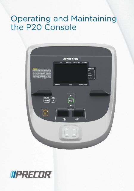
Operating and Maintainingthe P20 Console
Edition InformationOPERATING AND MAINTAINING THE P20 CONSOLEP/N 300753-201 rev BCopyright © June 2011 <strong>Precor</strong> Incorporated. All rightsreserved. Specifications subject to change without notice.Trademark Note<strong>Precor</strong>, AMT, and EFX are registered trademarks and Preva isa trademark of <strong>Precor</strong> Incorporated. Other names in thisdocument may be the trademarks or registered trademarks oftheir respective owners.Intellectual Property NoticeAll rights, title, and interests in and to the software of thePreva Business Suite, the accompanying printed materials,any copies of such software, and all data collected via thePreva Business Suite, are exclusively owned by <strong>Precor</strong> or itssuppliers, as the case may be.<strong>Precor</strong> is widely recognized for its innovative, award-winningdesigns of exercise equipment. <strong>Precor</strong> aggressively seeks U.S.and foreign patents for both the mechanical construction andthe visual aspects of its product design. Any partycontemplating the use of <strong>Precor</strong> product designs is herebyforewarned that <strong>Precor</strong> considers the unauthorizedappropriation of its proprietary rights to be a very seriousmatter. <strong>Precor</strong> will vigorously pursue all unauthorizedappropriation of its proprietary rights.<strong>Precor</strong> Incorporated20031 142nd Ave NE, P.O. Box 7202Woodinville, WA 98072-40021-800-347-4404http://www.precor.com
Important Safety InstructionsThis apparatus (hereinafter referred to as the console) isintended to be shipped with new <strong>Precor</strong> exercise equipment(hereinafter referred to as the base unit). It is not packagedfor individual sale.WARNINGTo prevent injury, the console must beattached securely to the base unit following allassembly and installation instructions shippedwith the base unit. The console is intended tobe connected to AC mains power through thefurnished power supply ONLY. It should bepowered on only when installed as describedin the assembly and installation instructionsshipped with the base unit. The console isintended for use only with <strong>Precor</strong> fitnessequipment, not as a standalone device.Safety PrecautionsRead all instructions in the documentation provided with yourexercise equipment before installation of this device includingall assembly guides, user guides, and owner’s manuals.Always follow basic safety precautions when using thisequipment to reduce the chance of injury, fire, or damage.Other sections in this manual provide more details of safetyfeatures. Be sure to read these sections and observe all safetynotices. These precautions include the following:• Read all instructions in this guide before installing andusing the equipment and follow any labels on theequipment.• Make sure all users see a physician for a completephysical examination before they begin any fitnessprogram.
4 Operating and Maintaining the P20 Console• Il est conseillé de subir un examen médical complet avantd’entreprendre tout programme d’exercise. Si vous avez desétourdissements ou des faiblesses, arrêtez les exercicesimmédiatement.• Do not allow children, or people unfamiliar with theoperation of this equipment, on or near it. Do not leavechildren unsupervised around the equipment.• Make sure all users wear proper exercise clothing andshoes for their workouts and avoid loose or danglingclothing. Users should not wear shoes with heels orleather soles, and they should check the soles of theirshoes to remove any dirt and embedded stones. Theyshould also tie long hair back.• Never leave the equipment unattended when it is pluggedin. Unplug the equipment from its power source when it isnot in use, before cleaning it, and before providingauthorized service.Note: The optional power adapter is considered a powersource for self-powered equipment.• Use the power adapter provided with the equipment. Plugthe power adapter into an appropriate, grounded poweroutlet as marked on the equipment.• Care should be taken when mounting or dismounting theequipment.• Read, understand, and test the emergency stopprocedures before use.• Keep the power cord or optional power adapter and plugaway from heated surfaces.• Route power cables so that they are not walked on,pinched, or damaged by items placed upon or againstthem, including the equipment itself.• Ensure the equipment has adequate ventilation. Do notplace anything on top of or over the equipment. Do notuse on a cushioned surface that could block theventilation opening.• Assemble and operate the equipment on a solid, levelsurface.
Important Safety Instructions 5• Proper Location for Equipment For all equipment other than treadmills: Locate atleast 40 inches (1 meter) away from walls orfurniture on either side of the equipment, and 40inches (1 meter) away from objects behind theequipment. For treadmills: Locate at least 40 inches (1 meter)away from walls or furniture on either side of thetreadmill, and at least 80 inches (2 meters) awayfrom objects behind the treadmill.Important: These location standards should also be usedwhen positioning equipment away from sources of heat, suchas radiators, heat registers, and stoves. Avoid temperatureextremes.• Keep equipment away from water and moisture. Avoiddropping anything on or spilling anything inside theequipment to prevent electric shock or damage to theelectronics.• When using the treadmill, always attach the safety clip toyour clothing before beginning your workout. Failure touse the safety clip may pose a greater risk of injury in theevent of a fall.• Do not operate electrically powered equipment in dampor wet locations.• Never operate this equipment if it has a damaged cord orplug, if it is not working properly, or if it has been dropped,damaged, or exposed to water. Call for serviceimmediately if any of these conditions exist.• Maintain the equipment to keep it in good workingcondition, as described in the Maintenance section of theassembly and maintenance guide. Inspect the equipmentfor incorrect, worn, or loose components, and thencorrect, replace or tighten prior to use.• If you plan to move the equipment, obtain help and useproper lifting techniques.• Equipment Weight Restrictions: Do not use the treadmillif you weigh more than 500 pounds (225 kg). If you weighmore than 350 pounds (160 kg), do not run on thetreadmill. For all other fitness equipment, the weight limitis 350 pounds (160 kg).
6 Operating and Maintaining the P20 Console• Use the equipment only for its intended purpose asdescribed in this manual. Do not use accessoryattachments that are not recommended by <strong>Precor</strong>. Suchattachments may cause injuries.• Do not operate the equipment where aerosol (spray)products are being used or where oxygen is beingadministered.• Do not use outdoors.• Do not attempt to service the equipment yourself, exceptto follow the maintenance instructions in this manual.• Never drop or insert objects into any opening. Keep handsaway from moving parts.• Do not set anything on the stationary handrails,handlebars, control console, or covers. Place liquids,magazines, and books in the appropriate receptacles.• Do not lean on or pull on the console at any time.CAUTION: DO NOT remove the cover, or you may risk injury dueto electric shock. Read the assembly and maintenance guidebefore operating. There are no user-serviceable parts inside.Contact Customer Support if the equipment needs servicing. Foruse with single phase AC power only.Hazardous Materials and Proper DisposalThe batteries within self-powered equipment containmaterials that are considered hazardous to the environment.Federal law requires proper disposal of these batteries.If you plan to dispose of your equipment, contact <strong>Precor</strong>Commercial Products Customer Support for informationregarding battery removal. Refer to Obtaining Service.Product Recycling and DisposalThis equipment must be recycled or discarded according toapplicable local and national regulations.Product labels, in accordance with European Directive2002/96/EC concerning waste electrical and electronicequipment (WEEE), determine the framework for the returnand recycling of used equipment as applicable throughout theEuropean Union. The WEEE label indicates that the product isnot to be thrown away, but rather reclaimed upon end of lifeper this Directive.
Important Safety Instructions 7In accordance with the European WEEE Directive, electricaland electronic equipment (EEE) is to be collected separatelyand to be reused, recycled, or recovered at end of life. Usersof EEE with the WEEE label per Annex IV of the WEEEDirective must not dispose of end of life EEE as unsortedmunicipal waste, but use the collection framework availableto customers for the return, recycling, and recovery of WEEE.Customer participation is important to minimize any potentialeffects of EEE on the environment and human health due tothe potential presence of hazardous substances in EEE. Forproper collection and treatment, refer to Obtaining Service.Regulatory Notices for CardiovascularExercise EquipmentThe regulatory information in this section applies to theexercise equipment and its control console.Safety Approvals for Cardiovascular Equipment<strong>Precor</strong> equipment has been tested and found to comply withthe following applicable safety standards.Cardiovascular Type Equipment:• CAN/CSA, IEC, EN 60335-1 (Household and similarelectrical appliances - Safety)• EN 957 (Stationary training equipment, class S/Bcompliant equipment)Radio Frequency Interference (RFI)This <strong>Precor</strong> exercise equipment conforms to the followingnational standards defining acceptable limits for radiofrequency interference (RFI).Federal Communications Commission, Part 15This equipment has been tested and found to comply with thelimits for a Class A digital device, pursuant to Part 15 of theFCC Rules. These limits are designed to provide reasonableprotection against harmful interference in a commercialinstallation. The equipment generates, uses, and can radiateradio frequency energy and, if not installed and used inaccordance with the owner’s manual instructions, can causeharmful interference to radio communications.
8 Operating and Maintaining the P20 ConsoleOperation is subject to the following two conditions: (1) thisdevice may not cause harmful interference, and (2) thisdevice must accept any interference received, includinginterference that may cause undesired operation.WARNINGPer FCC rules, changes or modifications notexpressly approved by the manufacturer couldvoid the user’s authority to operate theequipment.Industry CanadaThis device complies with RSS-210:2007 of the SpectrumManagement & Telecommunications Radio StandardsSpecification. Operation is subject to the following twoconditions: (1) this device may not cause harmfulinterference, and (2) this device must accept any interferencereceived, including interference that may cause undesiredoperation.This Class A digital apparatus complies with CanadianICES-003.Cet appareil numérique de la classe A est conforme à la normeNMB-003 du Canada.ATTENTION: Haute TensionDébranchez avant de réparerEuropean ApplicationsCE compliance is claimed to the following directives:• 2004/108/EC EMC Directive• 2006/95/EC LVD Directive• 2002/95/EC RoHS DirectiveDirective compliance has been verified to the followingstandards:• EN 55022• EN 55024• EN 60335-1• EN 60065 (P80 and PVS)
Important Safety Instructions 9Electrical Recommendations: 120 V and 240V TreadmillsNote: This is a recommendation only. NEC (National ElectricCode) guidelines or local region electric codes must befollowed.You should have received a power cable that meets your localelectrical code requirements along with the equipment.<strong>Precor</strong> treadmills must be connected to a 20 amp individualbranch circuit that can be shared only with one PVS. If youneed additional help with the power connections contact your<strong>Precor</strong> authorized dealer.Important: An individual branch circuit provides a hot conductorand neutral conductor to a receptacle. The conductors must not belooped, "daisy-chained", or connected to any other conductors.The circuit must be grounded according to NEC guidelines or localregion electric codes.Figure 1: North American 120-volt, 20-amp power receptacleFigure 2: North American 240-volt, 20-amp power receptacle
10 Operating and Maintaining the P20 ConsoleElectrical Recommendations: All EquipmentExcluding TreadmillsNote: This is a recommendation only. NEC (National ElectricCode) guidelines or local region electric codes must befollowed.For equipment fitted with a P80 console or Personal ViewingSystem (PVS) screen a separate power connection isrequired. For a 20 amp branch circuit up to 10 screens can beconnected. If the branch circuit has any other devices pluggedinto the circuit the number of screens must be reduced by thewattage of the other devices.Note: The typical splitter power cords that have IEC-320 C13and C14 plugs have a recommended maximum capacity offive screens.Figure 3: IEC-320 C13 and C14 plugsObtaining ServiceDo not attempt to service the equipment except formaintenance tasks. If any items are missing, contact yourdealer. For more information regarding customer supportnumbers or a list of <strong>Precor</strong> authorized service centers, visitthe <strong>Precor</strong> web site at http://www.precor.com.For the most current manuals, go to http://www.precor.com.
Table of ContentsImportant Safety Instructions ................................................... 3Safety Precautions .................................................................................3Hazardous Materials and Proper Disposal .................................... 6Product Recycling and Disposal ....................................................... 6Regulatory Notices for CardiovascularExercise Equipment ...................................................................... 7Electrical Recommendations:120 V and 240 V Treadmills ...................................................... 9Electrical Recommendations: All EquipmentExcluding Treadmills .................................................................. 10Obtaining Service ................................................................................ 10Getting Started .........................................................................13Activating the Console for Self-Powered Equipment ................ 13Setting Up the Console ............................................................ 15Viewing the Odometer Informational Menu ................................ 18Viewing the Club Settings Menu ..................................................... 21Introducing Users to the P20 Console..................................... 27Using the Touch Heart Rate Feature ............................................. 27Using a Chest Strap Transmitter .................................................... 29Using the Treadmill Safety Clip ...................................................... 29Treadmill Auto Stop (Automatic Stop) Function .................... 31Using SmartRate® ............................................................................... 32Starting a Workout .................................................................. 33Starting a Preset Programmed Workout ...................................... 33Pausing and Restarting an Exercise Session ................................ 35Ending a Session.................................................................................. 36Programs.................................................................................. 39Maintenance ............................................................................ 43Cleaning the Console and Display ................................................. 43
12 Operating and Maintaining the P20 Console
Chapter 1Getting StartedThe P20 console offers administrators and members theability to set defaults that meet their specific needs.Activating the Console for Self-PoweredEquipment<strong>Precor</strong> equipment is either self-powered or externallypowered using an optional power adapter. Self-poweredequipment requires the user exercise to initialize the console.This section provides more detail about powering equipment.Activating the Console for Self-Powered EquipmentOn self-powered equipment, when a user starts exercising,the console initializes and displays the Welcome banner. Aminimum rate of motion must be maintained for theWelcome banner to appear. The words PEDAL FASTER (orthe equivalent message depending on the equipment type)appear in the display when the rate of motion drops below theminimum requirements.The equipment saves its battery charge by moving into ashutdown mode. If the user does not maintain the minimumrate of motion, a 30-second shutdown process begins.In this mode, the console displays a countdown indicator andignores all keypresses. If no movement is detected or the rateof motion remains below the minimum, the indicator changesas the countdown continues.Note: The user can resume exercising before the countdownperiod elapses and the program will continue from the pointat which it was paused.
14 Operating and Maintaining the P20 ConsoleOptional Use of the Power AdapterAn optional AC power adapter provides sustained power tothe equipment. This adapter allows you to change settingswithout having to pedal the equipment. To purchase thepower adapter, contact your dealer.If you purchase the optional power adapter, you must alsopurchase the internal cable kit. The kit supplies the cable,bracket, and fasteners that connect the power adapter to thelower electronics board.CAUTION: The internal cable kit must be installed by authorizedservice personnel. Do not attempt installation on your own as youcould void the <strong>Precor</strong> Limited Warranty. For more information,refer to Obtaining Service.Important: If this equipment includes a P80 console, the optionalpower adapter and the internal cable kit must still be installed toprovide continuous power to the base unit and support its internalbattery.Once the internal cable kit is installed, you can plug theoptional power adapter into the equipment. Plug the oppositeend into the appropriate power source for your equipment(120 V or 240 V). Review the safety instructions found at thebeginning of this manual before using the power adapter.CAUTION: When the optional power adapter is in use, make surethat the power supply cord does not create a safety hazard. Keepit out of the way of traffic and moving parts. If the power supplycord or power conversion module is damaged, it must be replaced.The control console functions differently when the poweradapter is connected. Because the power adapter provides aconstant source of power, a user can pause for brief periodswithout initiating shutdown procedures. When the pause timelimit expires and the user has not resumed exercising, theconsole returns to the Welcome screen. The default pausetime is 30 seconds for all fitness equipment. Refer to themanual for your control console for instructions on setting orchanging the pause time limit.
Chapter 2Setting Up the ConsoleUse the System mode to configure settings in ways thatbenefit your users and your facility. The System menu isvisible only to administrators and registered servicetechnicians. Changes made to these settings are saved to thefitness equipment.The system settings are:• Odometer Settings• Club Settings
16 Operating and Maintaining the P20 ConsoleIdentifying Parts of the ConsoleThe following diagram provides information about the consolekeys. The number and actions of the console keys may differslightly depending on the type of equipment.Figure 4: P20 Console DisplayNote: Some equipment has both an intensity (resistance)indicator and an incline indicator. Other equipment may onlyhave one type of indicator.Table 1. Parts of the P20 console displayNumber Part NameUpper textdisplayLower textdisplaySmartRate®and HeartRate iconDetailsScrolls information to guide the userDisplays graphical information about yourworkout progressSmartRate® displays a range of heart rateintensity to the user. The heart-shapedicon pulses in sync with the detectedheartbeat.
Setting Up the Console 17Number Part NameEnter keyWorkout keyInput Up keyInput DownkeyGO keyReset keyIntensityindicatorInclineindicatorIncline UpIncline DownIntensity UpkeyIntensityDown keyDetailsDisplays preset workoutsUse to navigate user menusUse to navigate user menusUse to begin your workout(Pause/Reset on tread consoles)Displays level of resistance. This windowcan appear on single and dual indicatorequipment.Displays level of inclineTreadmill, EFXIncreases incline levelTreadmill, EFXDecreases incline levelTreadmill, EFXIncreases resistance or speed. This keyappears on single indicator equipment.Decreases resistance or speed. This keyappears on single indicator equipment.Welcome StateThe equipment is in the Welcome state when it is on, but notactually in use. This means that there is no exercise session,data entry, or diagnostic operation in progress.When the equipment is in the Welcome state:• WELCOME scrolls on the program display. This isreferred to as the Welcome banner.• PRESS GO OR PROGRAMS TO START scrolls in the textdisplay.• The heart rate signal is the only segment activated.• On the treadmill, the belt is not moving and the lift motoris off.
18 Operating and Maintaining the P20 ConsoleOn self-powered equipment, the battery initializes when youbegin working out. You must maintain a minimum rate ofmotion for the Welcome banner to appear. PEDAL FASTER(or the equivalent message depending on the equipmenttype) appears in the display when the battery is low or whenthe rate of motion drops below the minimum requirements.Viewing the Odometer Informational MenuEach piece of equipment provides information about its use,as well as its software version, serial number, usage log, andevent log. In most cases, you will only access this informationif directed to do so by <strong>Precor</strong>® Customer Support.To view the odometer informational menu:1. Press the following keys in the order presented.Reset (Pause/Reset on tread consoles)Input UpEnterNote: Only two seconds are allowed between keypresses.If a key is not pressed, the console display returns to theWelcome banner.2. Press Up or Down to navigate the menu.3. Press GO to select a test.4. Press Programs once to return to the Odometer menu ortwice to return to the Welcome banner.OdometerThe odometer tracks equipment usage by the number of unitstraveled. The Odometer Units and Values table providesinformation on how usage is tracked depending on theequipment type.The odometer information updates under these conditions:• Every 30 minutes• At the end of a course• When an event occursIf the course is terminated by turning off the power, then theodometer data for that workout is lost.
Setting Up the Console 19Event LogThe software is able to detect a variety of events. The eventlog holds a maximum of 30 events. After the log reaches 30events, older events are erased to make room for newer ones.Note: There is a shortcut for quick access to the Event Logreport. From the Welcome banner, press Reset (Pause/Reseton tread consoles) for five seconds. If there are no events, thewords STUCK KEY appear and then the console returns tothe Welcome banner.Each event log entry contains the following information:• Event number• Odometer value when the event occurred• Hour meter value at the time the event occurred• Current drawn by the motor when the event occurred(treadmill only)The following table contains a list of events detectable by thesoftware.Table 2. Event log numbers and descriptionsEvent Description of EventNumber00 Upper PCA memory location event02 RAM location event03 EEPROM checksum event05 Depressed key at power up09 Lower PCA memory test event10 Line Frequency out of acceptable range11 Watchdog (Upper PCA) low voltage power12 Watchdog (Lower PCA) low voltage power13 Fan at incorrect speed (version 1 treadmills)14 Fan fail (Lower PCA)15 AC input voltage too high16 AC input voltage too low20 Too many maximum power requests in one second21 Too many maximum consecutive power requests
20 Operating and Maintaining the P20 ConsoleHour MeterEvent Description of EventNumber22 No motor pulses at start up23 Motor pulses missing after start up24 Reduce speed requested, speed is not reducing26 Motor pulse width incorrect27 Too much drive motor current28 Temperature too high29 Excessive AC input current30 Communications event lower board to upper board31 Incorrect Communications event upper board tolower board32 Communication event upper board to lower board33 Incorrect communications event lower board toupper board40 Lift motion detected42 Lift position value out of range43 Zero switch not found44 Un-commanded lift motion45 Lift going in the wrong direction50 Too much brake (magnet) current53 Cannot read target, cannot find home switch54 Target pulses lost during operation55 Brake home switch activated unexpectedly60 Auto Stop sensor failure (treadmill)61 Auto Stop not present (treadmill)Tracks the number of hours that a piece of equipment hasrun. The equipment also tracks elapsed minutes, but the valuethat displays is rounded up the nearest full hour.
Setting Up the Console 21Lower SoftwareDisplays the software version (part number) of the motordrive unit.U-Base SoftwareDisplays the software version and part number of the upperunit application software.U-Boot SoftwareDisplays the software version and part number of the upperboot loader software.Usage LogDisplays information about program usage including:• Programs that have been used• Number of times each program has been used• Length of time each program was usedTo view the usage log:1. From the Odometer Information menu, press Enter.2. Press Input Up or Input Down to navigate the list.3. Press Programs once to return to the menu or twice toreturn to the Welcome banner.Viewing the Club Settings MenuUse Club settings to customize the equipment for your club orfacility and to view useful product information. These featuresremain hidden from club patrons and can only be accessedusing special keypresses.The equipment must be in the Welcome state before you canaccess the Club Settings menu. To access the Welcome state,you must power the equipment. For self-powered equipment,use the optional power adapter, otherwise you will have tomaintain the minimum rate of motion. For more informationon self-powered equipment, refer to Activating the Display.The changes made in the Club Settings mode become thedefault settings when the display resets to the Welcomestate.
22 Operating and Maintaining the P20 ConsoleClub Setting ValuesTo view the Club Settings menu:1. Press the following keys in the order presented.Reset (Pause/Reset on tread consoles)EnterInput UpEnterProgramsEnterInput UpEnterNote: Only two seconds are allowed between keypresses.If a key is not pressed, the console display returns to theWelcome banner.2. Press Up or Down to navigate the menu.3. Press GO to select a test.4. Press Programs once to return to the Odometer menu ortwice to return to the Welcome banner.LanguageSelect the preferred language for the console display.Max Cool Down TimeSelect the maximum amount of time the equipment willremain in the cool down mode. The available values are 0 to 5minutes. Cool down time is the period of time following thecompletion of a program when the user exercises at areduced work rate.Max Pause TimeThis setting limits how long a equipment will remain in thepaused state during a workout before resetting. The availablevalues are 1 to 120 seconds.Set Max CrossRampSelect the maximum height on the EFX CrossRamp. Thedefault is 20, which is also the maximum height.
Setting Up the Console 23Max Resistance (<strong>Bike</strong>, AMT)Select the maximum resistance that a user can program whileusing the equipment.Max Workout TimeSet a maximum workout time per session. Choose a time limitbetween 1 and 90 minutes, or select No Limit if you do notwant to set a workout time limit.Default Workout TimeWhen set to ON, the default workout time will be 30 minutes.When set to OFF, program times will be the value in the maxworkout time setting.Unit of MeasureSelect U.S. standard or metric displays.Max Speed (Treadmill)Set the maximum speed that a user can program while usingthe equipment.Max Incline (Treadmill)Set the maximum percent incline that a user can programwhile using the equipment.Resistance Range (<strong>Bike</strong>)Workout intensity can be set to the following levels:• Low (rehab)• Medium (low torque)• High (high torque)
24 Operating and Maintaining the P20 ConsoleSafety Code (Treadmill)The Safety Code feature prevents use of the treadmill until apassword is entered. Select Enable to use this feature andpress the following keys in the order presented.ProgramsEnterInput DownInput UpWhen the safety code is enabled, the display will be in theWelcome state until a key is pressed. If a key is pressed, theword PASSWORD? appears in the display. If a password isnot entered within two minutes, the equipment resets to theWelcome banner.Table 3. Equipment values and their associated rangesEquipment ValueAllWorkoutprogramDefaultValueManualAll Weight (lb) 150poundsAll Weight (kg) 68kilogramsAll Age 35 yearsoldAllAllWorkouttimeMaximumpause time30minutes120seconds(treadmill)ValueRange50 - 350pounds23 - 160kilograms15 - 99years1 - 90minutes1 - 120secondsValue ChangeIncrements1 pound1 kilogram1 year1 minute (dataentry) / 1second(measurement)AllTarget heartrate30seconds(EFX, bike,AMT)130
Setting Up the Console 25Equipment Value DefaultValueAll Unit of U.S.measurementAllModelnumberDependenton productAll Time meter 0 hoursAll Event log 0 entriesAll Odometer 0 unitsValueRangeAll Cool down 5 minutes 1 - 5minutesAllAllAllAllData entryinactivitytime outTime countupTime countdownCoursesegments30seconds00:00minutes30:00minutesEnteredtime/20 ifless than20 minuteworkout.Value ChangeIncrements1 minute<strong>Bike</strong>, AMT<strong>Bike</strong>ResistancelevelResistancerangeIf over 20minuteworkout,segment =1 minute1 1 - 20(AMT)HighTreadmill Speed 1 mph1.6 kph1 - 25(bike)LowMediumHigh.5 - 12mph.8 - 19.3kph10.1 mph.1 kph
26 Operating and Maintaining the P20 ConsoleEquipment ValueTreadmillQuick StartcoursesegmentDefaultValue1 minuteTreadmill Max incline 15 percentinclineTreadmill Mid-sessionchangetimeoutClimber Steps perminuteEFX MaxCrossRampValueRange0 - 15percent5 seconds None30 - 80 520 1 - 20 1Value ChangeIncrements0.5 percent
Chapter 3Introducing Users to the P20ConsoleCAUTION: Before beginning any fitness program, see yourphysician for a thorough physical examination. Seek advice fromyour physician to learn the target heart rate appropriate for yourfitness level.The P20 console offers an easy-to-follow display and multipleprograms to help people meet their exercise needs. Thesensitive keypad lets them select data and control theirworkout session and SmartRate® provides a visual aid thatmonitors heart rate and workout intensity at a glance.Important: Please review the following sections in this guide withyour users before allowing them to use the fitness equipment:• Important Safety Instructions• Getting Started• Using the Safety Clip (for treadmill only)Using the Touch Heart Rate FeatureNote: Touch heart rate performance may vary based on auser’s physiology, fitness level, age, and other factors. Youmay experience an erratic readout if your hands are dry, dirty,or oily, or if the skin on your palms is especially thick. Wearinghand lotion can also cause an erratic readout. In addition,make sure that the sensors are clean to ensure proper contactcan be maintained.
28 Operating and Maintaining the P20 ConsoleTo use the touch heart rate feature, place the palm of yourhands directly on the metal heart rate sensors on theequipment’s handlebars. To ensure a more accurate heartrate readout, make sure you follow these tips:• Both hands must grip the sensors for your heart rate toregister.• It takes a number of consecutive heart beats (15-20seconds) for your heart rate to register.• When gripping the sensors, do not grip tightly. Keep aloose, cupping hold. Holding the grips tightly can affectthe reading.• As you work out, your perspiration will help transmit yourheart rate signal. If you have difficulty using the handheldgrips to determine your heart rate, try the sensors againlater in the workout to see if you can obtain a heart ratesignal.• If the touch heart rate feature does not work for you,<strong>Precor</strong> recommends that you use a chest transmitterstrap.Figure 5: Heart rate target zonesCAUTION: Your heart rate should never exceed 85% of yourmaximum aerobic heart rate. Your maximum heart rate is equal to220 minus your age.
Introducing Users to the P20 Console 29Using a Chest Strap TransmitterWARNINGSignals used by the Chest Strap Transmitter(or heart rate strap) may interfere withpacemakers or other implanted devices.Consult your physician and the manufacturersof your Chest Strap Transmitter andimplanted device before using a Chest StrapTransmitter.Wearing a chest strap transmitter during your workoutprovides steady heart rate information. For the equipment todetect your heart rate, you must grip the touch heart ratesensors or wear a chest strap transmitter while exercising. Inthe presence of both touch and wireless data, the touch datatakes precedence and will display.Note: To receive an accurate reading, the strap needs to be indirect contact with the skin on the lower sternum (just belowthe bust line for women).To use a chest strap transmitter:1. Carefully dampen the back of the strap with tap water.Important: Do not use deionized water. It does not have theproper minerals and salts to conduct electrical impulses.2. Adjust the strap and fasten it around your chest. Thestrap should feel snug, not restrictive.3. Make sure that the chest strap is right-side-up, lieshorizontally across, and is centered in the middle of yourchest.4. Test the chest strap placement by checking the heart ratefunction on the equipment. If a heart rate is registering,your chest strap placement is correct. If the equipmentdoes not register a heart rate, readjust the strap andrecheck the heart rate function.
30 Operating and Maintaining the P20 ConsoleUsing the Treadmill Safety ClipThe treadmill is equipped with two different stop functions,which behave as follows:If the user …Presses down on the redSTOP buttonPulls on the lanyardattached to the safetyclip and trips the restartswitchThen the treadmillbelt …Slows to a stopSlows to a stopAnd the console …Shows that theexercise workout ispausedShows the wordsPUSH TO RESETSWITCH and anarrow pointing tothe Restart switchThe restart switch is located just below the console andimmediately behind the red STOP button, as shown in thefollowing illustration. When it is tripped, the bar pops up,displaying the words PUSH TO RESET SWITCH on its frontside. The treadmill does not operate while these words arevisible.Figure 6: Restart switchInstruct users on how important it is to use the safety clipwhile exercising on the treadmill, and demonstrate how theyshould attach it to their clothing near the waistline.
Introducing Users to the P20 Console 31If the restart switch trips during exercise, perform thefollowing steps:1. Reattach the safety clip if necessary.2. Press the restart switch down until it clicks, returning it toits normal position.Note: If the restart switch trips, all information about thecurrent workout is deleted.3. Start the workout from the beginning, reducing the timeas needed to account for the amount of exercise that hasbeen completed.Figure 7: Attaching the safety clipTreadmill Auto Stop (Automatic Stop)FunctionImportant: The default setting for this feature is ON. Anadministrator can turn off this feature in the System Settings;however, <strong>Precor</strong> recommends it remain ON.The Auto Stop (Automatic Stop) feature is designed tobring the treadmill to a gradual stop when it is not in use. Thismight occur if a user steps off the treadmill before the end ofa workout and leaves the treadmill running.Sixty seconds after a treadmill workout starts or resumes, theequipment begins Auto Stop monitoring. If a user is detected,then no message appears, and the selected workoutcontinues.
32 Operating and Maintaining the P20 ConsoleIf no user is detected after an additional 30 seconds, theconsole displays the message NO USER DETECTED,STOPPING IN 10 SECONDS as notification of the pendingstop. During the display of this message, a ten secondcountdown begins. If a user does not override the countdown,the belt comes to a gradual stop after the countdown iscomplete.Note: Users weighing more than 90 pounds (41 kg) aredetected within the speed and position limits of the feature.Users weighing 50 pounds (22.7 kg) to 89 pounds (40.5 kg)may not be detected depending on their speed and location.Always be aware of and follow the console’s instructions forproper operation.Using SmartRate®The <strong>Precor</strong> SmartRate® technology is a precise, easy-to-readheart rate monitor that helps users achieve their bestpersonalized workouts. SmartRate displays actual heart rateinformation in relation to the user’s target zone for weightloss and cardiovascular training. This feature is visible duringall workouts. In addition, some equipment includes a HeartRate Control (HRC) workout that automatically adjustsintensity to keep a user’s heart rate in its target zone. Formore information, refer to Programs.CAUTION: Before beginning any fitness program, see yourphysician for a thorough physical examination. Seek advice fromyour physician to learn the target heart rate appropriate for yourfitness level.To test your heart rate:1. Begin a workout by pressing QUICK START, or byselecting a preset workout followed by pressing GO.2. Grasp the handheld heart rate sensors with both hands.Depending on the type of equipment, the letters "Hr"appear, or a blinking heart displays while the equipmentreads your heart rate. After a few moments, your heartrate displays in beats per minute. The blinking segmentsin the SmartRate field indicate the current zone of yourheart rate: Warm Up, Fat Burn, Cardio, or High.
Chapter 4Starting a WorkoutCAUTION: If you are using a treadmill, be sure to attach thesecurity clip to your clothing before starting your workout.The equipment is in the Welcome state when the wordsPRESS GO OR PROGRAMS TO START scroll across thescrolling text display area and the word WELCOME scrolls onthe upper text display. Press Reset (Pause/Reset on treadconsoles) to display the Welcome screen.From the Welcome screen, there are two ways to begin aworkout:• Press GO (Quick Start method).This action launches the Manual program. Calculations,such as calories used, are based on a 150-lb (68 kg),35-year old individual. You can complete a workout usingthis program with default values, or you can changeworkout settings.• Press Programs and enter your personal data.Important: On self-powered equipment, the battery initializeswhen you begin moving. A minimum rate of motion must bemaintained for the Welcome screen to appear. The words PEDALFASTER (or the equivalent message depending on the equipmenttype) appear in the display when the rate of motion drops belowthe minimum requirements.
34 Operating and Maintaining the P20 ConsoleStarting a Preset Programmed WorkoutPreset workouts are a great way to tailor your workouts toyour fitness goals, stay challenged, and add variety to yoursessions. The P20 includes the following preset programs:• Manual• Interval 1-1• Interval 1-2• Weight Loss• Basic Heart Rate Control• Hill Climb• Cross Country• Random• AerobicTo begin using a program:1. On the Welcome screen, press Programs.2. Press Programs or Input Up/Input Down repeatedly tomove through the program list.3. To begin your workout immediately, press Go when thename of the program you want appears in the text displayarea. To add personal data such as age or weight, pressEnter.Before an exercise session begins, a three-secondcountdown appears in the upper text display.Entering Personal DataPersonal data settings include your age, weight, and how longyou want to work out.The equipment calculates calories burned and SmartRatetargets based on your age and weight.Note: The interface may be slightly different based on thetype of equipment.
Starting a Workout 35To enter personal data:1. On the Welcome screen, press Programs, then Enter.2. Press the Input keys to change the default value.3. Press Enter. The weight input screen displays. Press theInput keys to change the default value.4. Press Enter. The age input screen displays. Press theInput keys to change the default value.5. Press GO or Enter to begin your workout.The equipment counts down and 1, 2, 3 display on thescreen. The words STARTING WORKOUT scroll in thelower text display.Terminating Data EntryThere are several ways to terminate data entry depending onthe type of equipment.TIMEOUT: If a key is not pressed for more than 30 seconds,you are returned to the Welcome screen.RESET: If Reset is pressed before beginning the workout, youare returned to the Welcome screen. During a workout, pressReset once to see the Summary screen and twice to return tothe Welcome screen. On the treadmill, press Pause/Resetonce to pause the workout, twice to see the Summary screen,and three times to return to the Welcome screen.GO: Press GO to begin a selected exercise program. Dataentry is bypassed and default values are used.ENTER: Normally, Enter is pressed then the displayed value isaccepted. If there is more data to enter, then the user isprompted for that data. If there is no more data to enter, theselected program is started using the previously entered datafor workout Duration, Weight, and Age.Pausing and Restarting an Exercise SessionWhen you interrupt a workout, the equipment responds inone of two ways, depending on how it is powered.
36 Operating and Maintaining the P20 ConsolePaused (Externally Powered Equipment)When you interrupt your workout, the words WORKOUTPAUSED - PRESS GO TO CONTINUE scroll across the textdisplay. The accumulated metrics (Time, Calories, Distance,and Average Speed) hold their current values and do notchange.To restart the program, press GO.If the equipment remains inactive for more than the maximumpause time, it displays the Summary screen with yourworkout metrics. After displaying the summary, it returns tothe Welcome screen.Pending Shutdown (Self-Powered Equipment)When you interrupt your workout, the words WORKOUTPAUSED - PEDAL TO CONTINUE scroll continuously acrossthe text display. It also displays the number of secondsremaining until the equipment shuts down.To restart the program during the countdown, begin pedaling.If the equipment remains inactive for more than the maximumpause time, it displays the Summary screen with yourworkout metrics.Ending a SessionCooling down is an important aspect of your workout becauseit helps reduce muscle stiffness and soreness by transportingexcess lactic acid out of the working muscles. In addition, afive minute cool down allows your heart rate to return to itsnormal, resting state.At the end of your workout, a Summary screen displays youraverage heart rate during your workout and your accumulatedworkout metrics.
Starting a Workout 37Understanding MetricsThree different types of metrics are captured during aworkout.Controlled MetricsMetrics that can be set and changed are:• Resistance Level (AMT, EFX, bike)• Speed (treadmill)• Incline (treadmill)• Steps/Minute (climber)Current Performance MetricsMetrics that describe the intensity of a workout in real timeare:• Calories/Minute, Calories/Hour• Heart Rate• Speed (treadmill, bike)• Revolutions/Minute (bike)• Strides/Minute (AMT, EFX)Accumulated MetricsMetrics that describe the overall performance throughout theentire exercise session are:• Time:Count-down ModeCount-up Mode• Calories• Distance:Average Strides/Minute (AMT, EFX)Average Speed (treadmill, bike)Floors (climber)
38 Operating and Maintaining the P20 Console
Chapter 5ProgramsPreset workouts are a great way to tailor your workouts toyour fitness goals, stay challenged, and add variety to yoursessions. In the following figures, the elevated areas show thework expenditure for each preset program.ManualIn this program, resistance and speed changes are completelyunder your control. The profile is initially a flat line. Anyincrease or decrease made in one program segment willincrease or decrease all remaining portions by the sameamount.Figure 8: Manual
40 Operating and Maintaining the P20 ConsoleInterval 1-1 and Interval 1-2The Interval programs are primarily for conditioning yourcardiovascular system. These programs are designed to raiseand lower your heart rate in a repeating fashion for auser-defined period of time by alternating rest and workintervals. Program intensity is adjustable.Figure 9: Interval 1-1Figure 10: 1-2 IntervalWeight LossThe program time is fixed at 28 minutes. The programconsists of four intervals, each lasting eight minutes. You canchange the resistance at any time during the work interval.Figure 11: Weight Loss
Programs 41Basic Heart Rate ControlThis program computes your target heart rate based on thecalculation, 60% of 220 minus your age. The equipmentadjusts resistance and/or incline to maintain your target heartrate while you work out.When a heart rate signal is not received, a heart shape with aquestion mark appears in the upper text display. Recheck yourhand grip on the handheld sensors or the placement of yourchest strap.Figure 12: Basic HRCNote: For the unit to detect your heart rate, you must grip thehandheld heart rate sensors or wear a chest strap whileexercising. In the presence of both handheld and wirelessdata, the handheld data takes precedence and displays.Hill ClimbThis preset program simulates hill climbing. The program isfixed at 30 minutes on most equipment, and the resistance ispredetermined. Any increase or decrease made in oneprogram segment will increase or decrease all remainingportions by the same amount.Figure 13: Hill Climb
42 Operating and Maintaining the P20 ConsoleCross CountryThe purpose of the preset program is to simulate an outdoorrunning experience. In this case, you can change the overallprofile or intensity of the program (resistance) at any time;however, you cannot change the shape of the preset "hills"and "valleys" you see depicted on the display.Figure 14: Cross CountryRandomAerobicEvery time this program is selected, a different programprofile appears. The one-minute segments that appear in theprogram profile maintain a set resistance that you canoverride. The Random program has a default time limit, or youcan press STOP to complete your program sooner.This program is similar to an Interval program. You can set alength of time for your fitness session and you can specify thespeed and the incline or resistance.Figure 15: Aerobic
Chapter 6MaintenanceTo keep the equipment functioning properly, perform theminor maintenance tasks in this section at the intervalssuggested. Failure to maintain the equipment as described inthis section could void the <strong>Precor</strong> Limited Warranty.DANGERTo reduce the risk of electrical shock, alwaysdisconnect the equipment from its power sourcebefore cleaning it or performing any maintenancetasks. If the equipment uses an optional poweradapter, disconnect the adapter.Cleaning the Console and DisplayThe console requires little maintenance once installed. <strong>Precor</strong>recommends that you clean the console before and after eachexercise session.To remove dust and dirt from the console:• Wipe all exposed surfaces with a soft cloth that you havemoistened with a solution of 30 parts of water to 1 part ofSimple Green® (for more information, visitwww.simplegreen.com).Important: Do not use any acidic cleaners. Doing so will weakenthe paint or powder coatings and void the <strong>Precor</strong> LimitedWarranty. Never pour water or spray liquids directly on theconsole or console’s screen.• It is important to avoid using any corrosive chemicals on theconsole or screen.• Always dampen the cloth and then clean the screen. Be sureto spray the cleaning liquid onto the cloth, not the console, sothat drips do not seep into the console.• Apply the cleaner with a soft, lint-free cloth. Avoid using grittycloths.
44 Operating and Maintaining the P20 ConsoleNotes:
<strong>Precor</strong> Incorporated20031 142nd Avenue NEP.O. Box 7202Woodinville, WA USA 98072-4002P20 Console OM 300753-201 rev B, en28 June 2011
Assembling and Maintaining<strong>RBK</strong> 800-<strong>Series</strong><strong>Recumbent</strong> Exercise <strong>Bike</strong>s
Edition InformationASSEMBLING AND MAINTAINING <strong>RBK</strong> 800-SERIESRECUMBENT EXERCISE BIKESP/N 300716-201 rev CCopyright © February 2011 <strong>Precor</strong> Incorporated. All rightsreserved. Specifications subject to change without notice.Trademark Note<strong>Precor</strong>, AMT, and EFX are registered trademarks and Preva isa trademark of <strong>Precor</strong> Incorporated. Other names in thisdocument may be the trademarks or registered trademarks oftheir respective owners.Intellectual Property NoticeAll rights, title, and interests in and to the software of thePreva Business Suite, the accompanying printed materials,any copies of such software, and all data collected via thePreva Business Suite, are exclusively owned by <strong>Precor</strong> or itssuppliers, as the case may be.<strong>Precor</strong> is widely recognized for its innovative, award-winningdesigns of exercise equipment. <strong>Precor</strong> aggressively seeks U.S.and foreign patents for both the mechanical construction andthe visual aspects of its product design. Any partycontemplating the use of <strong>Precor</strong> product designs is herebyforewarned that <strong>Precor</strong> considers the unauthorizedappropriation of its proprietary rights to be a very seriousmatter. <strong>Precor</strong> will vigorously pursue all unauthorizedappropriation of its proprietary rights.<strong>Precor</strong> Incorporated20031 142nd Ave NE, P.O. Box 7202Woodinville, WA 98072-40021-800-347-4404http://www.precor.com
Important Safety InstructionsRead the following precautions thoroughly before you beginassembly, and save them afterward for future reference.Safety PrecautionsAlways follow basic safety precautions when using thisequipment to reduce the chance of injury, fire, or damage.Other sections in this manual provide more details of safetyfeatures. Be sure to read these sections and observe all safetynotices. These precautions include the following:• Read all instructions in this guide before installing andusing the equipment and follow any labels on theequipment.• Make sure all users see a physician for a completephysical examination before they begin any fitnessprogram.• Il est conseillé de subir un examen médical complet avantd’entreprendre tout programme d’exercise. Si vous avez desétourdissements ou des faiblesses, arrêtez les exercicesimmédiatement.• Do not allow children, or people unfamiliar with theoperation of this equipment, on or near it. Do not leavechildren unsupervised around the equipment.• Make sure all users wear proper exercise clothing andshoes for their workouts and avoid loose or danglingclothing. Users should not wear shoes with heels orleather soles, and they should check the soles of theirshoes to remove any dirt and embedded stones. Theyshould also tie long hair back.• Never leave the equipment unattended when it is pluggedin. Unplug the equipment from its power source when it isnot in use, before cleaning it, and before providingauthorized service.Note: The optional power adapter is considered a powersource for self-powered equipment.
4 Assembling and Maintaining <strong>RBK</strong> 800-<strong>Series</strong> <strong>Recumbent</strong> Exercise <strong>Bike</strong>s• Use the power adapter provided with the equipment. Plugthe power adapter into an appropriate, grounded poweroutlet as marked on the equipment.• Care should be taken when mounting or dismounting theequipment.• Read, understand, and test the emergency stopprocedures before use.• Keep the power cord or optional power adapter and plugaway from heated surfaces.• Route power cables so that they are not walked on,pinched, or damaged by items placed upon or againstthem, including the equipment itself.• Ensure the equipment has adequate ventilation. Do notplace anything on top of or over the equipment. Do notuse on a cushioned surface that could block theventilation opening.• Assemble and operate the equipment on a solid, levelsurface.• Proper Location for Equipment For all equipment other than treadmills: Locate atleast 40 inches (1 meter) away from walls orfurniture on either side of the equipment, and 40inches (1 meter) away from objects behind theequipment. For treadmills: Locate at least 40 inches (1 meter)away from walls or furniture on either side of thetreadmill, and at least 80 inches (2 meters) awayfrom objects behind the treadmill.• Keep equipment away from water and moisture. Avoiddropping anything on or spilling anything inside theequipment to prevent electric shock or damage to theelectronics.• Do not operate electrically powered equipment in dampor wet locations.• Never operate this equipment if it has a damaged cord orplug, if it is not working properly, or if it has been dropped,damaged, or exposed to water. Call for serviceimmediately if any of these conditions exist.• Maintain the equipment to keep it in good workingcondition, as described in the Maintenance section of theassembly and maintenance guide. Inspect the equipmentfor incorrect, worn, or loose components, and thencorrect, replace or tighten prior to use.
Important Safety Instructions 5• If you plan to move the equipment, obtain help and useproper lifting techniques. Refer to the "Moving theEquipment" section of the assembly and maintenanceguide.• Use the equipment only for its intended purpose asdescribed in this manual. Do not use accessoryattachments that are not recommended by <strong>Precor</strong>. Suchattachments may cause injuries.• Do not operate the equipment where aerosol (spray)products are being used or where oxygen is beingadministered.• Do not use outdoors.• Do not attempt to service the equipment yourself, exceptto follow the maintenance instructions in this manual.• Never drop or insert objects into any opening. Keep handsaway from moving parts.• Do not set anything on the stationary handrails,handlebars, control console, or covers. Place liquids,magazines, and books in the appropriate receptacles.• Do not lean on or pull on the console at any time.CAUTION: DO NOT remove the cover, or you may risk injury dueto electric shock. Read the assembly and maintenance guidebefore operating. There are no user-serviceable parts inside.Contact Customer Support if the equipment needs servicing. Foruse with single phase AC supply only.Educating UsersTake time to educate users about the Important SafetyInstructions found in both the User Reference Manual andProduct Owner’s Manual. Explain to your club or facilitypatrons that they should observe the following precautions:• Hold onto a stationary handrail or handlebar whileassuming the starting position on the equipment.• Face the console at all times.• Hold on to a stationary handrail or handlebar with onehand whenever you operate the console keys with theother hand.
6 Assembling and Maintaining <strong>RBK</strong> 800-<strong>Series</strong> <strong>Recumbent</strong> Exercise <strong>Bike</strong>sHazardous Materials and Proper DisposalThe batteries within self-powered equipment containmaterials that are considered hazardous to the environment.Federal law requires proper disposal of these batteries.If you plan to dispose of your equipment, contact <strong>Precor</strong>Commercial Products Customer Support for informationregarding battery removal. Refer to Obtaining Service.Product Recycling and DisposalThis equipment must be recycled or discarded according toapplicable local and national regulations.Product labels, in accordance with European Directive2002/96/EC concerning waste electrical and electronicequipment (WEEE), determine the framework for the returnand recycling of used equipment as applicable throughout theEuropean Union. The WEEE label indicates that the product isnot to be thrown away, but rather reclaimed upon end of lifeper this Directive.In accordance with the European WEEE Directive, electricaland electronic equipment (EEE) is to be collected separatelyand to be reused, recycled, or recovered at end of life. Usersof EEE with the WEEE label per Annex IV of the WEEEDirective must not dispose of end of life EEE as unsortedmunicipal waste, but use the collection framework availableto customers for the return, recycling, and recovery of WEEE.Customer participation is important to minimize any potentialeffects of EEE on the environment and human health due tothe potential presence of hazardous substances in EEE. Forproper collection and treatment, refer to Obtaining Service.Regulatory Notices for the RFID ModuleWhen equipped with a control console as described in thisdocument, this equipment may include a radio-frequencyidentification (RFID) module. The RFID module has beencertified to operate at temperatures between -20ºC and 85°C(-4°F and 185°F).
Important Safety Instructions 7Radio Frequency Interference (RFI)The RFID module conforms to the following nationalstandards defining acceptable limits for radio frequencyinterference (RFI).Federal Communications Commission, Part 15This equipment has been tested and found to comply with thelimits for a Class A digital device, pursuant to Part 15 of theFCC Rules. These limits are designed to provide reasonableprotection against harmful interference in a commercialinstallation. The equipment generates, uses, and can radiateradio frequency energy and, if not installed and used inaccordance with the owner’s manual instructions, can causeharmful interference to radio communications.Operation is subject to the following two conditions: (1) thisdevice may not cause harmful interference, and (2) thisdevice must accept any interference received, includinginterference that may cause undesired operation.WARNINGPer FCC rules, changes or modifications notexpressly approved by the manufacturer couldvoid the user’s authority to operate theequipment.Industry CanadaThis device complies with RSS-210:2007 of the SpectrumManagement & Telecommunications Radio StandardsSpecification. Operation is subject to the following twoconditions: (1) this device may not cause harmfulinterference, and (2) this device must accept any interferencereceived, including interference that may cause undesiredoperation.This Class A digital apparatus complies with CanadianICES-003.Cet appareil numérique de la classe A est conforme à la normeNMB-003 du Canada.ATTENTION: Haute TensionDébranchez avant de réparer
8 Assembling and Maintaining <strong>RBK</strong> 800-<strong>Series</strong> <strong>Recumbent</strong> Exercise <strong>Bike</strong>sEuropean ApplicationsCE compliance is claimed to the following directives:• 1999/5/EC R&TTE Directive• 2006/95/EC LVD Directive• 2002/95/EC RoHS DirectiveDirective compliance has been verified to the followingstandards:• EN 55022• EN 300 330-1 V1.5.1• EN 300 330-2 V1.3.1• EN 301 489-3 V1.4.1• EN 301 489-1 V1.8.1• EN 60950-1Regulatory Notices for CardiovascularExercise EquipmentThe regulatory information in this section applies to theexercise equipment and its control console.Safety Approvals for Cardiovascular Equipment<strong>Precor</strong> equipment has been tested and found to comply withthe following applicable safety standards.Cardiovascular Type Equipment:• CAN/CSA, IEC, EN 60335-1 (Household and similarelectrical appliances - Safety)• EN 957 (Stationary training equipment, class S/Bcompliant equipment)PVS and P80 Regulatory NoticeThis <strong>Precor</strong> equipment has been tested and found to complywith the following applicable safety standards.• CAN/CSA, UL, IEC, EN 60065 (Audio, video and similarelectronic apparatus - Safety)
Important Safety Instructions 9Radio Frequency Interference (RFI)This <strong>Precor</strong> exercise equipment conforms to the followingnational standards defining acceptable limits for radiofrequency interference (RFI).Federal Communications Commission, Part 15This equipment has been tested and found to comply with thelimits for a Class A digital device, pursuant to Part 15 of theFCC Rules. These limits are designed to provide reasonableprotection against harmful interference in a commercialinstallation. The equipment generates, uses, and can radiateradio frequency energy and, if not installed and used inaccordance with the owner’s manual instructions, may causeharmful interference to radio communications.WARNINGPer FCC rules, changes or modifications notexpressly approved by <strong>Precor</strong> could void theuser’s authority to operate the equipment.Industry CanadaThis Class A digital apparatus complies with CanadianICES-003.Cet appareil numérique de la classe A est conforme à la normeNMB-003 du Canada.ATTENTION: Haute TensionDébranchez avant de réparerEuropean ApplicationsCE compliance is claimed to the following directives:• 2004/108/EC EMC Directive• 2006/95/EC LVD Directive• 2002/95/EC RoHS DirectiveDirective compliance has been verified to the followingstandards:• EN 55022• EN 55024• EN 60335-1• EN 60065 (P80 and PVS)
10 Assembling and Maintaining <strong>RBK</strong> 800-<strong>Series</strong> <strong>Recumbent</strong> Exercise <strong>Bike</strong>sElectrical Recommendations: All EquipmentExcluding TreadmillsNote: This is a recommendation only. NEC (National ElectricCode) guidelines or local region electric codes must befollowed.For equipment fitted with a P80 console or Personal ViewingSystem (PVS) screen a separate power connection isrequired. For a 20 amp branch circuit up to 10 screens can beconnected. If the branch circuit has any other devices pluggedinto the circuit the number of screens must be reduced by thewattage of the other devices.Note: The typical splitter power cords that have IEC-320 C13and C14 plugs have a recommended maximum capacity offive screens.Figure 1: IEC-320 C13 and C14 plugsObtaining ServiceDo not attempt to service the equipment except formaintenance tasks. If any items are missing, contact yourdealer. For more information regarding customer supportnumbers or a list of <strong>Precor</strong> authorized service centers, visitthe <strong>Precor</strong> web site at http://www.precor.com.Obtaining Updated DocumentationCurrent documentation for Experience <strong>Series</strong> consoles andPreva Networked Fitness software is available athttp://www.precor.com/productmanuals. You may want tocheck in for updated information from time to time as theuniverse of Preva features expands.
Table of ContentsImportant Safety Instructions ................................................... 3Safety Precaution s .................................................................................3Educating Users .................................................................................... 5Hazardous Materials and Proper Disposal .................................... 6Product Recycling and Disposal ....................................................... 6Regulatory Notices for the RFID Module ....................................... 6Regulatory Notices for CardiovascularExercise Equipment ...................................................................... 8Electrical Recommendations: All EquipmentExcluding Treadmills .................................................................. 10Obtaining Service ................................................................................ 10Obtaining Updated Documentation .............................................. 10Assembling the Exercise <strong>Bike</strong> ...................................................13Unpacking the Equipment ................................................................. 14Hardware Kit (not to scale) .............................................................. 15Required Tools ...................................................................................... 15Attaching the Seat Back and Bottle Holder .................................. 16Installing the Upright Support and Cables .................................... 17Making Sure the Unit Is Stable ......................................................... 21Breaking in the Equipment ................................................................ 21Installing the Console .............................................................. 23Threading the Cable Assembly (P80) .......................................... 23Connecting Cables (P80) ................................................................. 25Completing the Console Installation (P80) ................................ 29Threading the Cable Assembly (P30 and P20) ......................... 29Connecting Cables (P30) .................................................................. 31Connecting Cables (P20) ................................................................. 32Completing the Console Installation (P30 and P20) ................ 33Verifying That the Heart Rate Display Is Operational .............. 33
12 Assembling and Maintaining <strong>RBK</strong> 800-<strong>Series</strong> <strong>Recumbent</strong> Exercise <strong>Bike</strong>sMaintenance ............................................................................ 35Daily Cleaning ...................................................................................... 35Daily Inspection .................................................................................. 36Quarterly Maintenance ..................................................................... 37Storing the Chest Strap ...................................................................... 37Moving the Equipment ..................................................................... 38Long-Term Storage ............................................................................ 38Self-Powered Features ............................................................ 39Informational Displays Prior to Shutdown .................................. 40Symptoms of a Low Battery ............................................................ 40Using the Optional Power Adapter ................................................ 41The Optional Power Adapter Kit ..................................................... 41Replacing the Battery ........................................................................ 42Commercial Cardiovascular Equipment Limited Warranty .... 43
Chapter 1Assembling the Exercise <strong>Bike</strong>Important: The instructions in the following procedures aredescribed from the perspective of a person standing directly infront of the equipment (that is, on the opposite side of thecontrol console from a person using the equipment). Thesedescriptions may not match the names of certain parts in the partslist, because such parts are named relative to the back of theequipment.To prepare the exercise bike for assembly:• Open the box and assemble the components in thesequence presented in this guide.• Assemble and operate your equipment on a hard, levelsurface in the area intended for use.Important: Do not grasp any plastic parts of the unit whilelifting or moving the unit. The plastic parts are non-structuralcovers and are not capable of supporting the weight of theunit.• Assemble the equipment according to the guidelines inthis manual to ensure you do not void the <strong>Precor</strong> LimitedWarranty.Important: Any damage caused during installation is notcovered by the <strong>Precor</strong> Limited Warranty.• Attach all fasteners and partially tighten them. Do notfully tighten fasteners until instructed to do so.WARNINGYou will need assistance to assemble this unit.DO NOT attempt assembly by yourself.
14 Assembling and Maintaining <strong>RBK</strong> 800-<strong>Series</strong> <strong>Recumbent</strong> Exercise <strong>Bike</strong>sUnpacking the EquipmentThe shipping container for Precision <strong>Series</strong> exercise bikesconsists of the following items:• Wooden pallet• Cardboard base• Cardboard coverWARNINGDo not attempt to move the equipment off ofthe pallet by yourself. Have at least one otherperson help you, and use safe liftingtechniques.To unpack the bike:1. Carefully remove all staples securing the cover to thecardboard base.2. Lift the cover upward and set it aside.3. Carefully remove any staples holding the cardboard shieldin place in the center of the container.4. Lift the shield upward and set it aside.5. Cut all plastic ties securing the equipment in place.6. Remove the upright support from the container and set itdown near the spot where you plan to install theequipment.7. Remove the seat back and bottle holder from thecontainer and set them down with the upright support.8. With the help of at least one other person, lift the bodyassembly and move it forward until its front legs can belowered to the floor.9. With the help of at least one other person, carefully tiltthe body assembly forward until it rests on the wheelsattached to the front legs. Roll it to the location where youplan to install it, then tilt it back until it rests flat on thefloor.
Assembling the Exercise <strong>Bike</strong> 15Hardware Kit (not to scale)Before you begin the assembly, verify that the followinghardware items are packed with the equipment.Fasteners⁵₁₆-inch x ³₄-inchsockethead screwQuantity4¹₄-inch x ⁵₈-inchflathead machinescrew⁵₁₆-inch flat washer 44Upright supportmounting screw2Required Tools• ³₈-inch hex wrench• ¹₄-inch hex wrench• ⁵₃₂-inch hex wrench• #2 Phillips screwdriver• Wire cutter
16 Assembling and Maintaining <strong>RBK</strong> 800-<strong>Series</strong> <strong>Recumbent</strong> Exercise <strong>Bike</strong>sAttaching the Seat Back and Bottle HolderWhile the equipment is in use, the seat back flexes to supportusers of different shapes and sizes. Underneath the seat back,the bottle holder accommodates both left-handed andright-handed users.To attach the seat back:1. Insert the lower front edge of the seat back assemblyunder the seat.2. Swing the seat back assembly into place so that its fourscrew holes line up with the holes on the seat carriagebracket, as shown in the following illustration.Figure 2: Moving the seat back assembly into position3. Place four ⁵₁₆-inch washers onto four ⁵₁₆-inch x ³₄-inchsockethead screws.4. Insert the screws through the holes in the seat backassembly and thread them into the seat carriage bracket.5. Adjust the position of the seat back, then tighten thescrews completely using a ¹₄-inch hex wrench.
Assembling the Exercise <strong>Bike</strong> 17To attach the bottle holder:1. Position the bottle holder so that it wraps around the seatback assembly and rests on the tab on the back of theassembly. The front edges of the bottle holder should reston the handlebars and the two snap-in tabs should line upwith the small rectangular holes on the seat backassembly.2. Press the bottle holder forward until it locks into place.Installing the Upright Support and CablesDANGERDo not attempt to connect electrical power until allassembly procedures are complete and the consoleis properly installed.Before you begin this procedure, retrieve the cables for theconsole that you plan to install on this exercise bike. Thecables are packed with the console.Note: You will need the help of another person whileperforming the procedure.To prepare the bike for installation of the upright support:1. Retrieve the cables from the box in which the console wasshipped.2. Using a #2 Phillips screwdriver, remove the two #10 x1-inch self-tapping screws holding the top cover in place,then lift it off. Lift the cover from its front edge first, thendisengage its plastic tabs from the recesses on the rearcover into which they fit.Figure 3: Top cover removal
18 Assembling and Maintaining <strong>RBK</strong> 800-<strong>Series</strong> <strong>Recumbent</strong> Exercise <strong>Bike</strong>s3. Remove the three #10 x 1-inch self-tapping screwsholding the rear cover in place, then lift it off.Figure 4: Rear cover removal4. Remove the three #10 x 1-inch self-tapping screwsholding the left side cover in place, then pull the coveraway from the body assembly. Guide the cover aroundthe pedal crank, then remove it and set it aside.Figure 5: Left side cover removal5. Remove the tape holding the base unit data cable and theheart rate sensor cable in place inside the upright supportchannel.6. Slide the jack panel up and out of its bracket in the rightside cover.
Assembling the Exercise <strong>Bike</strong> 19To install the upright support and prepare the cables forconnection to the console:1. Attach the lower ends of the following cables to the innerside of the jack panel:• Ethernet cable• Television cable (for P80 console)• Power cable (for P80 console)2. Slide the jack panel back into its bracket in the right sidecover.3. Using a piece of tape or a plastic tie, bind together theupper ends of all cables.4. While your assistant holds the upright support in placeover the body assembly, thread the cables upwardthrough the support. When you are finished, use a pieceof tape to secure the upper connectors of the cables atthe top of the support.5. Slide the support into position so that its screw holes lineup with the corresponding holes on the body assembly, asshown in the following illustration.Note: If the support is positioned correctly, it rests on ametal tab in the upright support channel.Figure 6: Upright support insertionImportant: In the following step, be extremely careful not totrap or pinch any of the cables between the mounting screwsand their seats.
20 Assembling and Maintaining <strong>RBK</strong> 800-<strong>Series</strong> <strong>Recumbent</strong> Exercise <strong>Bike</strong>s6. Insert the two upright support mounting screws throughthe openings on the support and into the screw holes onthe body assembly. Tighten the mounting screwscompletely using a ³₈-inch hex wrench.Figure 7: Bolting the upright support into placeImportant: In the following two steps, be extremely carefulnot to trap or pinch any of the cables between the bike frameand any of the covers.7. Reposition the left side cover on the body assembly, thenreattach and tighten the #10 x 1-inch self-tapping screwsholding it in place.8. Repeat the previous step to reinstall the rear and topcovers.
Assembling the Exercise <strong>Bike</strong> 21Making Sure the Unit Is StableMake sure the unit is level before allowing anyone to use it.CAUTION: To eliminate movement, make sure the adjustable feetare in contact with the floor.To level the unit:1. Gently rock the unit. If there is any movement, ask yourassistant to tip the unit to one side while you locate theadjustable feet.2. Correct the height of each adjustable foot as follows.If you want to … Then turn the adjustable feet …Raise the unitLower the unitCounterclockwiseClockwiseImportant: Place the unit on a flat surface. Rotating theadjustable feet cannot compensate for extremely uneven surfaces.When you are finished adjusting the unit, place the unit on thefloor and recheck that it is level.Breaking in the Equipment<strong>Precor</strong> equipment does not require an actual break-in period.However, moving components such as belts, gears, andbearings can settle while the equipment is being stored orshipped. This can cause the equipment to operate with asmall amount of roughness or noise when it starts up for thefirst time.The equipment usually returns to smooth operation after aday or two of normal use. If it does not, contact your dealerfor assistance. For more information, refer to ObtainingService.
22 Assembling and Maintaining <strong>RBK</strong> 800-<strong>Series</strong> <strong>Recumbent</strong> Exercise <strong>Bike</strong>s
Chapter 2Installing the ConsoleTo make installation easier, all <strong>Precor</strong> Experience <strong>Series</strong>consoles use the same mounting hardware and connectorlocations whenever possible. The installation sequence forany of them is as follows:• Threading the cable assembly• Connecting cables• Completing the installation (tightening the mountingscrews and attaching the back cover)The following sections describe how to perform these tasks.Threading the Cable Assembly (P80)Earlier in the installation, you threaded the necessary cablesthrough the frame of the base unit and out the passthroughopening in the console mount. As you line up the back plateon the console with the console mount, you must make surethat the cable assembly passes correctly through theopenings in both components.
24 Assembling and Maintaining <strong>RBK</strong> 800-<strong>Series</strong> <strong>Recumbent</strong> Exercise <strong>Bike</strong>sImportant: Before you begin the following procedure, remove therear cover from the control console. To remove the cover, use yourfingernails to pry the lower edge loose, then swing the cover upand out as shown in the following illustration.Figure 8: Removing the access cover from the P80 consoleTo thread the cable assembly:1. Make sure that as much of each cable as possible passesthrough the opening in the middle of the console mounton the base unit.2. Position the console over the console mount.3. Rest the console on the console mount so that the notchon the bottom of the console’s back plate rests on therectangular hook at the bottom of the console mount, asshown in the following figure.Figure 9: Console positioning on base unit4. Tilt the console forward until it stops. Use one hand tosteady the console in this position, or ask your assistantto do so.
Installing the Console 25Connecting Cables (P80)After the console has been seated, separate the individualcables out of the end of the cable assembly and attach themto the appropriate circuit connectors inside the console. Referto the following diagram and table to identify the cables andconnectors.Figure 10: Cable connections, P80 consoleTable 1. P80 internal cable connectionsCable Connector Type CircuitConnectorLocationEthernet (LAN) Eight-contact modular, onround black cableTV inF-type coaxialPowerData from base unitTwo-contact plug,polarized and latchedEight-contact modular, onflat gray cable
26 Assembling and Maintaining <strong>RBK</strong> 800-<strong>Series</strong> <strong>Recumbent</strong> Exercise <strong>Bike</strong>sCable Connector Type CircuitConnectorLocationHeart rate sensors Four-contact strip, keyedSafety key(treadmills only)CSAFEAuto Stop sensor(treadmills only)Six-contact strip, keyedEight-contact modular, onflat gray cableFour-contact strip, keyedTo simplify installation and maintenance, route and connectcables 1 through 5 according to the following instructions.Note: In the illustrations in this section, some cables areomitted for the sake of clarity.Connecting the Television CableThe console’s television tuner is mounted inside the console’sback plate. The tuner includes a short cable adapter thatallows the television cable to be connected outside the backplate.To connect the television cable:1. Pull the cable out through the lower right corner of theback plate.2. Route the cable counterclockwise around the outside ofthe back plate.3. Attach the connector on the cable to the connector on thetuner cable and tighten the two connectors securely usingtwo ⁷₁₆-inch open-end wrenches. Position bothconnectors above the upper right corner of the back plate.4. Use a plastic tie to secure the connectors to the top of theback plate. Pass the tie through the two small holes nearthe upper right corner of the back plate, then wrap itaround the connectors and tighten it securely. Cut off andremove the protruding end of the tie.
Installing the Console 27The following illustration shows how the cable is positionedonce it is installed.Figure 11: Connecting the television cableConnecting the Ethernet and Base Unit Data CablesBoth the Ethernet and base unit data cables pass through thecutaway opening at the upper right corner of the back plateand connect to nearby modular jacks in the console. Becauseof this, it is important to exercise caution when connectingthe cables. The black Ethernet cable connects to a jack justunderneath the perforated metal bracket at the very top ofthe opening in the console. The gray base unit data cableconnects to a lower jack closer to the back plate.Refer to the following illustration for the correct position ofboth cables.CAUTION: If you connect the base unit data cable to the wrongjack, the equipment will not function.Figure 12: Connecting the Ethernet and base unit data cables
28 Assembling and Maintaining <strong>RBK</strong> 800-<strong>Series</strong> <strong>Recumbent</strong> Exercise <strong>Bike</strong>sConnecting the Heart Rate Sensor CableThe heart rate sensor cable passes through the cutawayopening at the upper left corner of the back plate, then downto the small circuit board at the lower left of the console. Thefollowing illustration shows how the cable should look once itis installed.Figure 13: Connecting the heart rate cableConnecting the Power CableLike the tuner, the console’s upper circuit board is equippedwith a cable adapter that relieves you of attempting to attacha cable to a recessed jack. To connect the power cable, routeit through the cutaway opening at the upper left corner of theback plate and plug it in to this adapter.The following illustration shows how the cable should lookonce it is installed.Figure 14: Connecting the power cable
Installing the Console 29Completing the Console Installation (P80)Before you complete the final installation steps, double-checkthe connections you have made. Make sure that all cables arefully and securely connected, and that any unneeded cablesare tied back properly.To complete the installation:1. Feed extra cable back into the neck tube.2. Tilt the control console backward (toward yourself) untilthe tab on the top edge of its back plate slides along thetop edge of the console mount and the screw holes alignproperly.3. Insert the four ⁵₈-inch flat head screws through the holesin the console mount and thread them into the holes inthe back plate on the console. Partially tighten the screwsusing a ⁵₈-inch hex wrench.4. Line up the two small tabs at the top of the console’s backcover with the slots at the top of the opening in theconsole case. Insert the tabs into the slots.5. Insert the remaining tabs on the back cover with thecorresponding slots on the console case.6. Press gently on the edges of the back cover to snap it intoplace.Threading the Cable Assembly (P30 andP20)Earlier in the installation, you threaded the necessary cablesthrough the frame of the base unit and out the passthroughopening in the console mount. As you line up the back plateon the console with the console mount, you must make surethat the cable assembly passes correctly through theopenings in both components.Important: Before you begin the following procedure, remove therear cover from the control console. Set the cover and its mountinghardware aside for later use.To thread the cable assembly:1. Make sure that as much of each cable as possible passesthrough the opening in the middle of the console mounton the base unit.2. Position the console over the console mount.
30 Assembling and Maintaining <strong>RBK</strong> 800-<strong>Series</strong> <strong>Recumbent</strong> Exercise <strong>Bike</strong>s3. Rest the console on the console mount so that the notchon the bottom of the console’s back plate rests on therectangular hook at the bottom of the console mount, asshown in the following figure.Figure 15: Console positioning on base unit4. Tilt the console forward until it stops. Use one hand tosteady the console in this position, or ask your assistantto do so.5. Pull all cables upward and forward until you can drapethem over the top of the console’s back plate.
Installing the Console 31Connecting Cables (P30)After the console has been seated, separate the individualcables out of the end of the cable assembly and attach themto the appropriate circuit connectors inside the console. Referto the following diagram and table to identify the cables andconnectors.Figure 16: Cable connections, P30 consoleTable 2. P30 internal cable connectionsCable Connector Type Circuit ConnectorLocationSafety keySix-contact strip, keyed(treadmills only)Auto Stop sensor Four-contact strip, keyed(treadmills only)Data from base unit Eight-contact modular,on flat gray cableHeart rate sensors Four-contact strip, keyed
32 Assembling and Maintaining <strong>RBK</strong> 800-<strong>Series</strong> <strong>Recumbent</strong> Exercise <strong>Bike</strong>sConnecting Cables (P20)After the console has been seated, separate the individualcables out of the end of the cable assembly and attach themto the appropriate circuit connectors inside the console. Referto the following diagram and table to identify the cables andconnectors.Figure 17: Cable connections, P20 consoleTable 3. P20 internal cable connectionsCable Connector Type Circuit ConnectorLocationData from base unit Eight-contact modular,on flat gray cableHeart rate sensorsFour-contact strip, keyedSafety key(treadmills only)Auto Stop sensor(treadmills only)Six-contact strip, keyedFour-contact strip, keyed
Installing the Console 33Completing the Console Installation (P30and P20)Before you complete the final installation steps, double-checkthe connections you have made. Make sure that all cables arefully and securely connected, and that any unneeded cablesare tied back properly.To complete the installation:1. Feed extra cable back into the neck tube.2. Tilt the control console backward (toward yourself) untilthe tab on the top edge of its back plate slides along thetop edge of the console mount and the screw holes alignproperly.3. Insert the four ⁵₈-inch flat head screws through the holesin the console mount and thread them into the holes inthe back plate on the console. Partially tighten the screwsusing a ⁵₈-inch hex wrench.4. Line up the two small tabs at the bottom of the console’sback cover with the slots at the bottom of the consolecase. Insert the tabs into the slots.5. Insert the two #8–32 x ¹₂-inch Phillips-head screws thatyou removed earlier into the holes at the top edge of theconsole’s back cover. Tighten the screws fully.Important: Use caution not to pinch the cables between theback cover and PVS mounting screw heads.6. Fully tighten the four mounting screws (partiallytightened in step 3) using a ⁵₃₂-inch hex wrench.Verifying That the Heart Rate Display IsOperationalTo verify that the heart rate display is operational:1. Begin exercising on the equipment.2. Grasp both touch-sensitive handlebars.Note: The heart rate is read within ten seconds. Duringthat time, the heart on the display flashes.3. Look at the HEART RATE display. After a few seconds, anumber appears indicating your heart rate.4. If a number does not appear in the HEART RATE display,check the cable connection to make sure it is properlyconnected.
34 Assembling and Maintaining <strong>RBK</strong> 800-<strong>Series</strong> <strong>Recumbent</strong> Exercise <strong>Bike</strong>s
Chapter 3MaintenanceTo keep the equipment functioning properly, perform theminor maintenance tasks in this section at the intervalsshown on the maintenance checklist. Failure to maintain theequipment as described in this section could void the <strong>Precor</strong>Limited Warranty.DANGERTo reduce the risk of electrical shock, alwaysdisconnect the equipment from its power sourcebefore cleaning it or performing any maintenancetasks. If the equipment is self-powered but alsouses the optional power adapter, disconnect theadapter.Daily Cleaning<strong>Precor</strong> recommends that you clean the equipment before andafter each exercise session. To remove dust and dirt from theequipment, wipe all exposed surfaces with a soft cloth thatyou have moistened with one of the following cleaners:• A solution of 30 parts of water to 1 part of Simple Green®(for more information, visit www.simplegreen.com)• ENVIR-O-SAFE oxygen enhanced cleaner or multi-taskcleaner concentrate, diluted according to themanufacturer’s instructions (for more information, visitwww.daleyinternational.com)
36 Assembling and Maintaining <strong>RBK</strong> 800-<strong>Series</strong> <strong>Recumbent</strong> Exercise <strong>Bike</strong>sAlternatively, you can clean the equipment with Athletixfitness equipment cleaning wipes (for more information, visitwww.athletixproducts.com)CAUTION: Read and follow the manufacturer’s instructions,particularly dilution instructions, before using any cleaner on<strong>Precor</strong> fitness equipment. Do not use concentrated cleaners at fullstrength, or acidic cleaners of any kind; such cleaners weaken theprotective finish on the equipment and void the <strong>Precor</strong> LimitedWarranty. Never pour water or spray liquids onto any part of theequipment. Allow the equipment to dry completely before using.Vacuum the floor underneath the equipment frequently toprevent the accumulation of dust and dirt that can interferewith its operation. Use a soft nylon scrub brush to clean thegrooves on equipment with foot pedals.Daily InspectionAt least once every day, examine the equipment for thefollowing problems:• Slipping belts• Loose fasteners• Unusual noises• Worn or frayed power cords• Any other indication that the equipment may be in needof serviceImportant: If you determine that the equipment needs service,disconnect all power connections (television, Ethernet, and power)and move the equipment away from the exercise area. Place anOUT OF SERVICE sign on the equipment and make it clear to allpatrons and other users that they must not use it.To order parts or to contact a <strong>Precor</strong> authorized serviceprovider in your area, refer to Obtaining Service.
Maintenance 37Quarterly Maintenance<strong>Precor</strong> recommends that you clean and inspect theequipment more thoroughly once every three months.To perform quarterly maintenance:1. Remove the cover panels.2. Vacuum out any debris, being careful not to bring thevacuum cleaner nozzle too close to any circuit board(unless your vacuum cleaner is protected against staticbuildup).3. Check the tension of both belts.4. Replace the cover panels.5. Wipe the exterior of the console with a damp sponge orsoft cloth, and dry with a clean towel. Keep water awayfrom electronic components to prevent electrical shock ordamage.6. Clean the touchscreen using a soft, lint-free clothdampened with a 91% isopropyl alcohol solution (eitherfull strength or diluted with an equal amount of water).Storing the Chest StrapIf you purchased the optional heart rate chest strap, store it ina place where it remains free of dust and dirt (for example, ina closet or drawer). Be sure to protect the chest strap fromextremes in temperature. Do not store it in a place that maybe exposed to temperatures below 32° F (0° C).To clean the chest strap, use a sponge or soft cloth dampenedin mild soap and water. Dry the surface thoroughly with aclean towel.
38 Assembling and Maintaining <strong>RBK</strong> 800-<strong>Series</strong> <strong>Recumbent</strong> Exercise <strong>Bike</strong>sMoving the EquipmentThe equipment is very heavy. If you plan to move it to a newlocation, obtain the help of an adult assistant and use properlifting techniques. If the equipment includes roller wheels onone end, use the wheels to reduce the load on yourself andyour assistant.To move the exercise bike:1. Disconnect, unplug, and remove all external connections(television, Ethernet, and power).2. Lift the rear feet to tip the bike forward onto its rollerwheels.3. Push the bike into its new location.4. Lower the rear feet to the floor.Long-Term StorageIf you do not expect anyone to use the equipment for a longtime, perform the following tasks to prepare it for storage:• If it has a power cord, disconnect the cord.• If it has an optional power adapter, connect the adapter toprevent damage to the internal battery.• Position it so that it will not become damaged and will notinterfere with people or other equipment.
Chapter 4Self-Powered FeaturesImportant: This chapter of the manual describes <strong>Precor</strong> fitnessequipment that can operate without being connected to ACpower. This includes units equipped with P40 or P20 consoles.However, P80 consoles must be connected to AC power throughtheir power supplies to operate. For this reason, this chapter doesnot apply to units equipped with P80 consoles.On self-powered equipment, the system initializes anddisplays the Welcome screen when a user starts exercising. Aminimum rate of motion must be maintained for the banner toappear, as shown in the following table. When a person meetsthe requirements, the power that is generated allows theequipment to function properly.Table 4. Minimum requirements for operationEquipment Rate of MotionAMTEFXClimber<strong>Bike</strong>56 strides per minute (SPM)40 strides per minute (SPM)30 steps per minute20 revolutions per minute (RPM)Informational displays appear when the battery is low orwhen the rate of motion drops below the minimumrequirements. The display explains what to do to retainpower. If the messages are ignored, the equipment beginsshutdown procedures to maintain the charge of the battery.Refer to Informational Displays Prior to Shutdown.An optional power adapter can be purchased and providessustained power to the equipment. If you plan to change theclub settings, the power adapter is highly recommended. Topurchase the optional power adapter, check with your dealer.Refer to Obtaining Service.
40 Assembling and Maintaining <strong>RBK</strong> 800-<strong>Series</strong> <strong>Recumbent</strong> Exercise <strong>Bike</strong>sInformational Displays Prior to ShutdownThe equipment saves its battery charge by moving into ashutdown mode. If the user does not maintain the minimumrate of motion, a 30-second shutdown process begins.In this mode, the console displays a countdown indicator andignores all keypresses. If no movement is detected or the rateof motion remains below the minimum, the indicator changesas the countdown continues.Note: The user can resume exercising before the countdownperiod elapses and the program will continue from the pointat which it was paused.Important: If the equipment is connected to a CSAFE masterdevice, it follows a slightly different shutdown process. Tenseconds before the equipment shuts down, it ends the exercisesession and displays a reset message while it disconnects from theCSAFE master device. It ignores all keypresses during these lastten seconds.Symptoms of a Low BatteryIf no one has used the equipment for an extended period oftime, the battery may need recharging.Symptoms of a low battery include the following:• A flickering or erratic display• Loss of user and program information after the user stopsexercising, without any display of a workout summary or anotification of pending shutdownImportant: To maintain a constant power source, use the optionalpower adapter.
Self-Powered Features 41Using the Optional Power AdapterAfter connecting the power adapter to the equipment, plugthe opposite end into the appropriate power source (120 V or240 V).CAUTION: When the optional power adapter is in use, make surethat the power supply cord does not create a safety hazard. Keepit out of the way of traffic and moving parts. If the power supplycord or power conversion module is damaged, it must be replaced.The control console functions differently when the poweradapter is connected. Because the power adapter provides aconstant source of power, a user can pause for brief periodswithout initiating shutdown procedures. When the pause timelimit expires and the user has not resumed exercising, theconsole returns to the Welcome screen. The default pausetime is 30 seconds for all fitness equipment. Refer to themanual for your control console for instructions on setting orchanging the pause time limit. To learn how to install thepower adapter, refer to The Optional Power Adapter Kit.The Optional Power Adapter KitIf you purchase the optional power adapter, you must alsopurchase the internal cable kit. The kit supplies the cable,bracket, and fasteners that connect the power adapter to thelower electronics board.CAUTION: The internal cable kit must be installed by authorizedservice personnel. Do not attempt installation on your own as youcould void the <strong>Precor</strong> Limited Warranty. For more information,refer to Obtaining Service.Important: If this equipment includes a P80 console, the optionalpower adapter and the internal cable kit must still be installed toprovide continuous power to the base unit and support its internalbattery.Once the internal cable kit is installed, you can plug theoptional power adapter into the equipment. Plug the oppositeend into the appropriate power source for your equipment(120 V or 240 V). Review the safety instructions found at thebeginning of this manual before using the power adapter.
42 Assembling and Maintaining <strong>RBK</strong> 800-<strong>Series</strong> <strong>Recumbent</strong> Exercise <strong>Bike</strong>sReplacing the BatteryThe equipment’s battery is built to last for a long time.However, if you feel that the battery may need replacing,check with an authorized service technician. Refer toObtaining Service.CAUTION: The battery stored inside the equipment containshazardous materials and must be disposed of according toHazardous Waste Regulations. Refer to Hazardous Materials andProper Disposal.
Chapter 5Commercial CardiovascularEquipment Limited WarrantyPLEASE READ THESE WARRANTY TERMS AND CONDITIONS CAREFULLY BEFOREUSING YOUR PRECOR INCORPORATED PRODUCT. BY USING THE EQUIPMENT, YOUARE CONSENTING TO BE BOUND BY THE FOLLOWING WARRANTY TERMS ANDCONDITIONS.Limited Warranty.<strong>Precor</strong> Incorporated warrants all new <strong>Precor</strong> products to be free from defects in materialsand manufacture for the warranty periods set forth below. The warranty periodscommence on the invoice date of the original purchase. This warranty applies only againstdefects discovered within the warranty period and extends only to the original purchaserof the product. Parts repaired or replaced under the terms of this warranty will bewarranted for the remainder of the original warranty period only. To claim under thiswarranty, the buyer must notify <strong>Precor</strong> or your authorized <strong>Precor</strong> dealer within 30 daysafter the date of discovery of any nonconformity and make the affected product availablefor inspection by <strong>Precor</strong> or its service representative. <strong>Precor</strong>’s obligations under thiswarranty are limited as set forth below.Warranty Periods and Coverage.All Commercial Cardiovascular Products (excluding StretchTrainer, StrengthProducts, and coverage specific to certain models and options as definedbelow):• Frame: 7 years• Treadmill drive motor: 5 years• Items subject to wear: 1 year• All other parts (including mechanical parts and electronic parts): 2 years• Labor: 1 year880 Line Commercial Cardiovascular Products (superseding the coverageabove where applicable):• Labor on the P80 console: 2 years• High wear items on the P80 console, including headphone jack, USB connector, andiPod® connector: 90 days
44 Assembling and Maintaining <strong>RBK</strong> 800-<strong>Series</strong> <strong>Recumbent</strong> Exercise <strong>Bike</strong>sOptions / AccessoriesMany options or accessories have components that are connected internally or mountedinside the electronic console. The following guidelines determine the warranty for thesecomponents. If the internal components are installed by the factory or by an authorizeddealer as part of the original sale and delivery, they have a warranty that is identical to thewarranty of the equipment in which they are connected or mounted. If the internalcomponents are not installed by the factory or by an authorized dealer as part of theoriginal sale and delivery, they have a 90 days parts and labor limited warranty. Allcomponents that are not internally connected have a 90 days parts only limited warranty.Satisfactory proof of purchase is required in all cases.Conditions and Restrictions.This warranty is valid only in accordance with the conditions set forth below:1. The warranty applies to the <strong>Precor</strong> product only whilea. it remains in the possession of the original purchaser and proof of purchase isdemonstrated.b. it has not been subjected to accident, misuse, abuse, improper service, ornon-<strong>Precor</strong> modification.c. claims are made within the warranty period.2. This warranty does not cover damage or equipment failure caused by electrical wiringnot in compliance with electrical codes or <strong>Precor</strong> owner’s manual specifications, orfailure to provide reasonable and necessary maintenance as outlined in the owner’smanual.3. <strong>Precor</strong> is not responsible for Internet connectivity to its products. This restrictionapplies to services, such as those provided by an Internet service provider (ISP), andalso to hardware related to Internet connectivity, such as Ethernet cabling, routers,servers and switches.4. <strong>Precor</strong> is not responsible for the quality of television, video, audio, or other mediasupplied to its products. This restriction applies to services, such as those providedby a cable or satellite television provider; to signal strength and clarity; and also tohardware related to the reception and delivery of television, video, audio, and othermedia. Such hardware can include (but is not limited to) audio, video, andradio-frequency (RF) cabling, connectors, receivers, modulators, combiners,distribution amplifiers, splitters, and so on.5. <strong>Precor</strong> cannot guarantee that the heart rate measurement system on its products willwork for all users. Heart rate measurement accuracy varies based on a number offactors, including the user’s physiology and age, the method in which the heart ratemeasurement system is used, external interference, and other factors that mayinfluence heart rate acquisition.6. Except in Canada, <strong>Precor</strong> does not pay labor outside the United States.7. Warranties outside the United States and Canada may vary. Please contact your localDealer for details.
Commercial Cardiovascular Equipment Limited Warranty 45This Limited Warranty shall not apply to:1. Software version upgrades.2. Software defects that do not materially and negatively affect the normal performanceof the product under normal conditions of use.3. Consumable goods or cosmetic items of the product, the exterior of which has beendamaged or defaced as a result of abuse, misuse, accident, improper service orinstallation, mishandling, or modification in design or construction not authorized by<strong>Precor</strong>.4. Repairs performed on <strong>Precor</strong> equipment missing a serial number or with a serial tagthat has been altered or defaced.5. Service calls to correct installation of the equipment or instruct owners on how to usethe equipment.6. Pickup and delivery involved with repairs.7. Any labor costs incurred beyond the applicable labor warranty period.Disclaimer and Release.The warranties provided herein are the exclusive warranties given by <strong>Precor</strong> andsupersede any prior, contrary or additional representations, whether oral or written. ANYIMPLIED WARRANTIES, INCLUDING THE WARRANTY OF MERCHANTABILITY ORFITNESS FOR A PARTICULAR PURPOSE THAT APPLY TO ANY PARTS DESCRIBEDABOVE ARE LIMITED IN DURATION TO THE PERIODS OF EXPRESS WARRANTIESGIVEN ABOVE FOR THOSE SAME PARTS. PRECOR HEREBY DISCLAIMS ANDEXCLUDES THOSE WARRANTIES THEREAFTER. Some States do not allow limitations onhow long an implied warranty lasts, so the above limitation may not apply to you. PRECORALSO HEREBY DISCLAIMS AND EXCLUDES ALL OTHER OBLIGATIONS OR LIABILITIES,EXPRESS OR IMPLIED, ARISING BY LAW OR OTHERWISE, WITH RESPECT TO ANYNONCONFORMANCE OR DEFECT IN ANY PRODUCT, INCLUDING BUT NOT LIMITEDTO: (A) ANY OBLIGATION, LIABILITY, RIGHT, CLAIM OR REMEDY IN TORT, WHETHEROR NOT ARISING FROM THE NEGLIGENCE OF PRECOR OR ITS SUPPLIERS (WHETHERACTIVE, PASSIVE OR IMPUTED); AND (B) ANY OBLIGATION, LIABILITY, RIGHT,CLAIM OR REMEDY FOR LOSS OF OR DAMAGE TO ANY EQUIPMENT. This disclaimerand release shall apply even if the express warranty set forth above fails of its essentialpurpose.Exclusive Remedies.For any product described above that fails to conform to its warranty, <strong>Precor</strong> will provide,at their option, one of the following: (1) repair; (2) replacement; or (3) refund of thepurchase price. <strong>Precor</strong> Limited Warranty service may be obtained by contacting theauthorized dealer from whom you purchased the item. <strong>Precor</strong> compensates Servicers forwarranty trips within their normal service area to repair commercial equipment at thecustomer’s location. You may be charged a trip charge outside the service area. THESESHALL BE THE SOLE AND EXCLUSIVE REMEDIES OF THE BUYER FOR ANY BREACH OFWARRANTY.
46 Assembling and Maintaining <strong>RBK</strong> 800-<strong>Series</strong> <strong>Recumbent</strong> Exercise <strong>Bike</strong>sEXCLUSION OF CONSEQUENTIAL AND INCIDENTALDAMAGES.PRECOR AND/OR ITS SUPPLIERS SHALL HAVE NO OBLIGATION OR LIABILITY,WHETHER ARISING IN CONTRACT (INCLUDING WARRANTY), TORT (INCLUDINGACTIVE, PASSIVE, OR IMPUTED NEGLIGENCE AND STRICT LIABILITY), OROTHERWISE, FOR DAMAGE TO THE EQUIPMENT, PROPERTY DAMAGE, LOSS OF USE,REVENUE OR PROFIT, COST OF CAPITAL, COST OF SUBSTITUTE EQUIPMENT,ADDITIONAL COSTS INCURRED BY BUYER (BY WAY OF CORRECTION OROTHERWISE) OR ANY OTHER INCIDENTAL, SPECIAL, INDIRECT, OR CONSEQUENTIALDAMAGES, WHETHER RESULTING FROM NONDELIVERY OR FROM THE USE, MISUSEOR INABILITY TO USE THE PRODUCT. This exclusion applies even if the above warrantyfails of its essential purposes and regardless of whether such damages are sought forbreach of warranty, breach of contract, negligence, or strict liability in tort or under anyother legal theory. Some states do not allow the exclusion or limitation of incidental orconsequential damages, so the above limitation may not apply to you.This warranty gives you specific legal rights, and you may also have other rights, whichvary from state to state.Complete this portion and keep for your records.Purchased From:Phone Number:Product/model:Serial number:Example: Dealer or store name.Example: Dealer or store telephone number.Example: AMT 885 or EFX 883.The serial number is found on the shipping container.Effective 1 November 2010P/N 36286-114
Commercial Cardiovascular Equipment Limited Warranty 47
48 Assembling and Maintaining <strong>RBK</strong> 800-<strong>Series</strong> <strong>Recumbent</strong> Exercise <strong>Bike</strong>s
<strong>Precor</strong> Incorporated20031 142nd Avenue NEP.O. Box 7202Woodinville, WA USA 98072-4002<strong>RBK</strong> 800-<strong>Series</strong> PAG/OM 300716-201 rev CWarranty #36286-11414 February 2011