Safety_Series_015_1965 - gnssn - International Atomic Energy ...
Safety_Series_015_1965 - gnssn - International Atomic Energy ...
Safety_Series_015_1965 - gnssn - International Atomic Energy ...

Create successful ePaper yourself
Turn your PDF publications into a flip-book with our unique Google optimized e-Paper software.
This publication is not longer validPlease see http://www-ns.iaea.org/standards/SAFETYifNo. 15SERIESRadioactiveWaste Disposalinto the GroundINTERNATIONAL ATOMIC ENERGY AGENCYVIENNA, <strong>1965</strong>
This publication is not longer validPlease see http://www-ns.iaea.org/standards/
This publication is not longer validPlease see http://www-ns.iaea.org/standards/RADIOACTIVE WASTE DISPOSALINTO THE GROUND
This publication is not longer validPlease see http://www-ns.iaea.org/standards/SAFETY SERIES No. 15RADIOACTIVE WASTE DISPOSALINTO THE GROUNDINTERNATIONAL ATOMIC ENERGY AGENCYVIENNA, <strong>1965</strong>
This publication is not longer validPlease see http://www-ns.iaea.org/standards/<strong>International</strong> <strong>Atomic</strong> <strong>Energy</strong> Agency.Radioactive waste disposal into the ground.Vienna, the Agency, <strong>1965</strong>.I l l p. (IAEA, <strong>Safety</strong> series, no. 15)621.039.7614.876THIS REPORT IS ALSO PUBLISHEDIN FRENCH, RUSSIAN AND SPANISHRADIOACTIVE WASTE DISPOSAL INTO THE GROUND,IAEA, VIENNA, <strong>1965</strong>STI/PUB/103
This publication is not longer validPlease see http://www-ns.iaea.org/standards/FOREWORDEncouragement in the use of safe methods in radioactive wastemanagement is a primary task of the <strong>International</strong> <strong>Atomic</strong> <strong>Energy</strong>Agency. In its <strong>Safety</strong> <strong>Series</strong> of publications it has already issuedPanel reports on Radioactive Waste Disposal into the Sea (1961) andon the Disposal of Radioactive Wastes into Fresh Water (1963). Theseare now joined by a third complementary report, on RadioactiveWaste Disposal into the Ground.It has been prepared by the Agency1s Secretariat on the basisof the discussions by an ad-hoc panel of experts convened by theAgency under the chairmanship of Mr. Mahmoud (United Arab Republic).Representatives of the Food and Agriculture Organizationof the United Nations, the World Health Organization and the EuropeanNuclear <strong>Energy</strong> Agency participated in the work of the Panel.The members represented a variety of disciplines and experiencepertinent to this broad and often complex subject.Most of the available information on disposal into the ground hascome from establishments that have routinely practised ground disposalon a large scale. The present work has provided an analyticalstudy of that information with emphasis on low and intermediate levelwastes rather than the specialized problems of storing high-levelwastes. It is hoped that it will be of direct interest to those who anticipatedisposing of radioactive wastes into the ground, whether ona large or small scale.
This publication is not longer validPlease see http://www-ns.iaea.org/standards/
This publication is not longer validPlease see http://www-ns.iaea.org/standards/CONTENTSLIST OF PARTICIPANTS ............. ............................................................. 1I. INTRODUCTION ....................................................................... 3II.III.SITE CHARACTERISTICS AFFECTING GROUNDDISPOSAL AND ITS INVESTIGATION ......................... 6(1) Climate ............................................................................... 6(2) Hydrology ............ .............................................................. 6(3) Geology and sub-surface investigation ........................ 8CHEMICAL REACTIONS OF WASTES IN THEGROUND AND THEIR PHYSICAL BEHAVIOUR.............. 12(1) Chemical reactions with minerals ............................... 12(2) Physical behaviour in the ground ................................ 15IV. MODES OF RELEASE............................................................. 21(1) Liquid wastes .................................................................... 21(2) Solid disposals .................................................................. 30V. EVALUATION OF SITES AND METHODSOF GROUND DISPOSAL ....................................................... 35(1) Potential exposures......................................................... 35(2) Site evaluation ................................................................. 37(3) Choice of shallow or deep disposal ............................. 39(4) The sm all-scale disposal of solid wastes ................ 41VI. STANDARDS AND CONTROL TECHNIQUES ..................... 45(1) Standards ....................................................................... 45(2) Control ........................................................................... 45(3) M onitoring.......................................................................... 47(4) Accidental Release .......................................................... 52VII. CONCLUSIONS........................................................................... 53(1) D isposal.............................................................................. 53(2) L iquid.................................................................................. 54
This publication is not longer validPlease see http://www-ns.iaea.org/standards/(3) Solid ................................. ................................................. 55(4) Storage............................................................................... 55(5) Accidental Releases ....................................................... 56APPENDIX I Pre-treatment for ground disposal ............... 57APPENDIX IIPhysics and chemistry of the movementof radioactive wastes in the ground .................. 64APPENDIX III Ground disposal operations .............................. 76APPENDIX IV Methods of site investigation .......................... 87GLOSSARY OF TERMS ...................................................................100REFERENCES .................................................................................... 104BIBLIOGRAPHY 110
This publication is not longer validPlease see http://www-ns.iaea.org/standards/LIST OFPARTICIPANTSChairmanK. A. MahmoudUnited Arab RepublicPanel m em bersA. Barbreau assisted byC. GailledreauL. Ber£kG. Di LorenzoE. GlueckaufW. J. KaufmanP.J. ParsonsJ. RotnickiK. T. ThomasFranceCzechoslovak Socialist RepublicItalyUnited KingdomUnited States of AmericaCanadaPolandIndiaConsultantP. DejongheBelgiumRepresentativesB. H. DieterichT. SiggerudWorld Health Organization<strong>International</strong> Council of ScientificUnions
This publication is not longer validPlease see http://www-ns.iaea.org/standards/G. Wortley Food and Agriculture OrganizationE. Wallauschek Organization for Economic Cooperationand Development/European Nuclear <strong>Energy</strong>AgencyScientific secretaryJ. F. Honstead <strong>International</strong> <strong>Atomic</strong> <strong>Energy</strong>AgencyNote:In the months immediately after the Panel, a number of internationalmeetings were held on allied subjects. For instance, a colloquiumon "The Retention and Migration of Radioactive Ions in Soils"was held at Saclay sponsored by The Commissariat &l 1Energie Atomiqueand the French section of the Health Physics Society; therewere also IAEA symposia on the "Treatment and Storage of HighlevelRadioactive Wastes" (Vienna 1962) and on "Radioisotopes inHydrology" (Tokyo 1963). Both of these broad programmes includedfringe subjects overlapping ground disposal that could usefully complementthe results of the Panel meeting.This report is thus a presentation of the results of the Panelmeeting augmented and modified as necessary by details from otherinternational meetings and recent publications considered appropriatefor inclusion in the text. It was drafted initially by J. F. Honsteadand expanded to its final form by P. J. Parsons from the Divisionof Health, <strong>Safety</strong> and Waste Disposal. Advice from C. A. Mawsonand D. W. Pearce is also gratefully acknowledged.2
This publication is not longer validPlease see http://www-ns.iaea.org/standards/I. INTRODUCTIONRadioactive waste from nuclear establishments must be treated,contained or disposed in such a way that it will endanger neither thesurrounding population nor the natural environment. Of the variousmethods used, disposal into the ground has sometimes proved to bean expedient and simple method. Where ground disposal has becomean established practice, the sites have so far been limited to thoseremote from population centres; but in other respects, such as inclimate and soil conditions, their characteristics vary widely. Experiencegained at these sites has illustrated the variety of problemsin radioactive waste migration and the resulting pollution and environmentalradiation levels that may reasonably be anticipated atother sites, whether remote from population centres or otherwise.Radionuclides can enter the soil either directly by the introductionof liquid wastes, or indirectly by water infiltrating through thesoil and leaching contaminants from the surface of solid waste buriedwith insufficient protection. The release may not be deliberate butmay result, for example, from an accidental rupture in a buriedpipe-line causing an escape of radioactive solution.However the release occurs, the soil and its attendant pore waterbecome contaminated, and this leads to the special case of radioactivepollution of the ground water. The pollution may disperse andbecome diluted or may remain close to the point of introduction, accordingto the chemical composition of both the soil constituents andthe water. The contaminants may retain their toxicity for longperiods, depending on their radioactive decay rates; so even thoughthey may stay underground for many years, there remains the possibilitythat the longer-lived nuclides will survive in a large enoughquantity and move far enough below ground to pollute a potable sourceof water.The pollution of ground water is a fairly common problem causednormally by domestic sewage, detergents or industrial wastes beingreleased with little or no control [1]. Radioactive wastes, by contrast,are discharged under controlled conditions, except in the caseof accidents; but there is always apprehension that the pollutioncould pass inadvertently into the human food chain. Anxiety maybe further increased when low-level ingestion can continue for sometime without noticeable effect and when the pollution can be recognizedonly by special instruments.3
This publication is not longer validPlease see http://www-ns.iaea.org/standards/The soil is a medium in which many pollutants are reduced inpotency, either by oxidation, by chemical and physical sorption, orby dilution or delay. Some chemical wastes [2, 3, 4], e. g. nitratesand chlorides, attenuate only by dilution but radioactive wastes normallyattenuate through sorption, dispersion, dilution and with thepassage of time. Thus any environment has a potential capacity toreceive limited quantities of radioactive waste material without creatingan unacceptable exposure potential.This report has attempted to analyse the factors that controlthis capacity and to assess the technical problems associated withground disposal. It has not attempted to compare the merits ofground disposal with those of other methods of radioactive wastemanagement.It may be expected that the discussion is of greatest pertinenceto sites that have a significant potential for retaining wastes releasedinto the ground. For other sites, the nature of the geological structure,the hydrological conditions or the proximity of populationcentres may reduce the amount of safe permissible release to uneconomicalamounts. In this situation ground disposal may appearfutile and unnecessarily hazardous; but it is often expedient neverthelessto bury solid waste or to sink containers of radioactive liquidunderground, in order to take advantage of earth shielding. Thisprocedure is more appropriately termed ground storage rather thanground disposal, since the objects may be unearthed and retrievedfor processing at any time.In contrast, ground disposal implies a more or less irreversiblepractice in which solids are intended for permanent burial and liquidsor leached radionuclides merge with the naturally occurring groundwater. These radioactive solutions are carried along by the groundwater mass at a velocity that may equal that of the water but whichis frequently far slower as a result of chemical interaction betweenthe radioactive ions and the earth materials.Eventually the contaminated water will emerge from belowground by seepage at a spring or stream or by penetrating the regionof an aquifer tapped by a well. It is at that potential area of emergenceor point of usage that the Health Physicist has to determinethe level of permissible contamination based on any possible hazardto population, livestock or biota. The corresponding permissibleamount of emerging contaminants at such a point and the probableattenuation afforded to contaminants in their passage through the soilfrom the disposal area to this point, provide bases for determiningthe type and permissible magnitude of ground disposal operations.4
This publication is not longer validPlease see http://www-ns.iaea.org/standards/Numerous disciplines are required in the evaluation of a sitefor ground disposal. Those principally involved are geology, soilchemistry, hydrology and engineering, but numerous other scientifictopics may have to be specially examined. This report has consideredthe relevant sectors of each discipline without becoming toodetailed in any one subject. It discusses the subsurface investigationsundertaken to disclose the nature of rock and soil, and associatedstudies of all the contained water-bearing formations. Conventionalexploratory tools may be applicable or geophysical methodsmay be used to supplement the lithological data. The chemistry ofthe soil is of m ajor importance since the sorptive capacity or affinityfor certain radionuclides will determine the useful attenuationby the soil while migrant contaminants are present in the groundwater. The movement of water underground is discussed togetherwith its effect on the migration of radioactive ions through both theaerated and saturated zones. Liquid wastes may be discharged intoshallow formations and so may modify the natural ground-water flowpattern or they may be injected at depth through boreholes penetratingporous formations. Experience of most types of liquid disposaloperations has been described in addition to experimental disposalsinto deep aquifers and rock strata and the proposed use of saltformations.In evaluating sites for waste disposal the preferred environmentalcriteria seldom occur together, so the balance of conflictingrequirements has to be examined. The merits and disadvantagesof shallow and deep disposal are considered in relation to the accuracyin predicting the future behaviour of the waste, and the abilityto monitor or control any subsequent movements.For the disposal of solid radioactive waste the potential hazardis normally much less than for liquid disposals. Various solid disposaloperations have been examined as well as those experimentalprocedures aimed at solidifying liquids and sludges, thus makingthem less leachable and therefore acceptable for burial in the lessexacting conditions of a solid disposal area.Most of the report is necessarily based on the experience gainedat establishments where ground disposal has been practised on alarge scale. For this reason a section is devoted to assessing theminimal requirements necessary before small quantities of solidwaste may be buried in the ground; for these small operations itis felt that the pre-operational survey could be curtailed to make itmore commensurate with the low inherent risks involved.5
This publication is not longer validPlease see http://www-ns.iaea.org/standards/II. SITE CHARACTERISTICS AFFECTING GROUND DISPOSALAND ITS INVESTIGATIONThe natural features determining the suitability of a site forground disposal include the climate, the type of soil and geologicalstructure, the hydrology, particularly in relation to undergroundwater sources, and the proximity to population centres.(1) ClimateWhere the climate is consistently damp there is obviouslygreater likelihood that radioactive materials will be leached. Asthe moisture, from rainfall or other precipitation, infiltrates throughthe soil at waste disposal sites it may come into contact with buriedsolid wastes or elute radionuclides already sorbed by the mineralcomponents in the soil. A rough guide to the measure of infiltrationlikely to cause this condition is the climatic feature known as the"Net Annual Precipitation Surplus". This is defined as the averageannual gross precipitation minus the total annual potential for evaporation.Unfortunately, it has to be applied with discretion sincemuch depends on the frequency and intensity of the precipitation withits corresponding "run-off". It is possible, for example, for a regionwith a negative net precipitation surplus to have surface waterinfiltrating the sub-soil if the rainfall occurs during infrequentviolent storms.Although wind and water are both natural transport media, itis the naturally occurring water below ground surface that playsoverwhelmingly the greatest part in spreading contamination fromburied radioactive waste. If the material becomes exposed to windor surface water, contamination may spread relatively fast, and anydelay anticipated from burial will be lost immediately.(2) HydrologyBecause of the special significance of the ground water, muchof the exploratory and research work has been devoted to the detailedexamination of sub-soils or rocks and the precise determination ofground water flow through these formations. P^or the special r e quirements of waste disposal, a typical examination would encompassthe environs of a proposed waste disposal ground with particularemphasis on the underground flow path of water at the site. The6
This publication is not longer validPlease see http://www-ns.iaea.org/standards/general information normally obtained in a ground water investigationwould certainly be useful [4, 5], The depth and thickness of theaquifer would be ascertained, the hardness, solids content, pH andchemical composition of the water would be measured and the yielddetermined after a period of sustained pumping. Such data wouldonly indicate broadly the average transmissibility of the waterbearingformation with associated estimates of the mean perm eability.While these details are pertinent to waste disposal problems,interest is centred more on the behaviour of specific water bodieswithin aquifers together with these subterranean flow patterns. Aquifersmust be identified and their boundaries determined; pressuremeasurements are required to map the piezom etric contours thatmay indicate, for example, unsuspected horizontal subdivisions withinan aquifer. Ideally, spot measurements of local ground waterflow should be taken. This information must then be examined in thelight of conditions prevailing at the time of measurement. Owingto seasonal changes in climate the sub-surface behaviour of groundwater should be expected to vary accordingly, particularly in humidregions.It is most unlikely that there will be prior information on localground water details before the investigation. However, there maybe records of rainfall or even records of flow in nearby rivers toindicate historically the anticipated variation in annual precipitationand run-off. Records of rainfall and ground water levels should bemaintained at a site as essential hydrological data which, as necessary,may be related to the prior long-term records. In this wayit may be possible to predict probable annual variations in groundwater conditions and, if flow nets have been described, to estimatetheir seasonal variation. In particular, it should be possible to distinguishlonger cyclical changes from extreme abnormal conditions.One of the main objectives in the ground water investigationwould be the determination of the flow path for water beneath theproposed site and, in particular, of the points at which it is likelyto appear at the surface [2, 6]. This "area of em ergence" may beat a spring, or where there is seepage into a stream, or near a wellthat penetrates and taps a connecting aquifer. Frequently this subsurfacepath for the water may be fairly obvious from topographicalfeatures, but it may be difficult to define if the water table lies atgreat depth, making observation and measurements proportionatelymore complicated [7, 8, 9],7
This publication is not longer validPlease see http://www-ns.iaea.org/standards/Probable variations in the ground water path should be examined;for instance, if a gravity aquifer is shallow the flow path would beinfluenced significantly by the lower boundary profile and thereforemore susceptible to variation with the recharge rate. Flow pathsin deep aquifers, conversely, would be less influenced by variationsin recharge rate.The time of passage for ground water to traverse the possibleroutes will have to be estimated and this is probably one of the mostdifficult yet important facets of the investigation. Without an estimateof the travel time it will be impossible to assess the probableretention of migrating radioactive ions.(3) Geology and sub-surface investigationIt is axiomatic that no investigation of aquifers can be completewithout a thorough understanding of the associated geological features[10,11]. To examine precisely the successive; horizons ofstrata, samples of geological materials must be collected and examined.The objects of such investigations, for the special requirementsof waste disposal, are directed towards the permeability ofthe various formations [12] and the isolation of their mineralogicalcomponents for sorption and ion-exchange measurements. For consolidatedrock, the conventional method of rotary drilling and theextraction of core samples is sufficient for these purposes. Forthe permeable sedimentary rocks, physical examination of undisturbedsamples and permeability checks may be carried out; whereasfor the intrinsically impermeable rocks, water flow is restrictedto fissures whose presence may be revealed only by in-situmeasurement.The investigation of unconsolidated and granular deposits maybe undertaken by conventional methods of drilling but sampling re quirements may be different in order to secure specimens suitablefor non-standard examination. In soils that are partially dry,a boreholemay be sunk by means of a churn drill or auger, and conventionalsampling carried out with tools appropriate for the type of soil.Those that have a large range of particle sizes, e. g. gravels, aredifficult to sample except in a disturbed state by auger or bailer, andreconstituted samples of such soil may be the best that can be obtainedfor examination. Where the soils are sorted into smaller,more uniform grain size, e.g. sands, it is sometimes better to usewashboring methods and certainly preferable to sample in the un
This publication is not longer validPlease see http://www-ns.iaea.org/standards/d isturbed state r e g a rd le s s o f w hether the s o il is d ry o r saturated.A visu al exam ination of undisturbed sam p les would indicate the h om ogeneity of the soil o r whether it was obviously com posed of su cce ssiv e lam inations of contrasting w e ll-sorte d soil. An exam ple ofthe lam inated type of stru ctu re, a coh esion less fine sand containingle s s than 5% silt, is shown in F ig. 1. Such ob servation s are n e c e s sa ry when the p erm ea b ility o f the m edium is one of the p rin cip a ldetails sought fro m the in vestigation .F ig -1Cross-section through an undisturbed sam ple o f lam inated sand.L am inated m a teria ls have d ifferen t p e rm e a b ilitie s a cco rd in gto the d ire ctio n o f w ater flow and are term ed a n isotro p ic. Whensam p les o f undisturbed granular s o ils are tested fo r p erm ea b ilityin the laboratory, water is passed along the axis of each cylin d rical9
This publication is not longer validPlease see http://www-ns.iaea.org/standards/sam ple that was p rev iou sly orien ted v e rtica lly in the ground. Theinduced flow th erefore corresp on d s to v e rtica l flow in the field andp asses a cro ss the la yers of soil that are n orm ally oriented clo se tothe horizontal plane. It is usual th erefore for laboratory perm eabilitiesto be low er than the horizontal field perm eability parallel to suchla y ers. Visual examination w ill also indicate whether the fine fr a c tion of a soil sam ple (silts, clays), which includes any cla y -m in era lcomponent, is distributed throughout the m atrix or whether it is con centrated in pockets or la yers. This is important since the sorptioncapacity is often associated d irectly with the quantity and availabilityo f clay m in eral. Clays in th em selves are not su bjected to the in ten sive exam ination they r e c e iv e in n orm a l s o il in vestigation s d irected, for instance, to the determination of shear strength and com p re ssib ility . The in terest in this m a terial is centred on its in trin sic im perm eability and whether clay strata are su fficien tly "tight"to form an im penetrable boundary to an aquifer. With consolidatedm aterials anisotropy can be as prevalent as in unconsolidated soilsbut it may no longer be assumed that the higher perm eabilities lie closeto the h orizon tal plane. Such form a tion s m ay have been su bjectedto earth m ovem en ts and the resu ltin g faulting o r fold in g m ay haveleft the strata in clin ed at any angle.In deep form ation s w here econ om y dictates that d rillin g shouldbe fast and w here detailed sam pling is m ore d ifficu lt, the req u iredin form ation is obtained by appropriate alternative m ethods. G eophysicallogging [13] m ay be applied fo r exploratory studies, p a rticularly w here se v e ra l aquifers m ay be stacked above each other asin sedim entary form ations or basalt. T yp ical w ells [14] bored withp ercu ssion equipment in dry m aterials m ay be as much as 40 cm ind ia m eter, w hich on en try into w a te r-sa tu ra te d m a te ria l w ould beca sed at a red u ced d iam eter of, say, 15 cm . G eop h ysical loggin gin such holes may include h ole-diam eter, gam m a-ray, electric-flow -m eter, tem perature or w a ter-resistivity logging. In drilling throughlava the wall of the hole may be sm ooth and only slightly larger thanthe bit, whereas in block y basalt it would be rough and la rg er and inunconsolidated m aterial the w alls would cave in to produce a la rgeo v er-cu t. In such m aterials the h ole-d ia m eter method and gam m a-ray logging can usefully supplem ent the lith ologic log from d rillcuttings. W a te r-re s is tiv ity , tem p era tu re and flo w -m e te r log gin gappear m ore useful in the recogn ition of aqu ifers, indicating v a ria tion in the concentration of d issolved salts, the differential tem peraturebetw een w ater fro m differen t o rig in s, and v e rtica l flow within10
This publication is not longer validPlease see http://www-ns.iaea.org/standards/a w ell. W here only few b oreh oles are sunk the resu lts m ay be augmented by s e is m ic su rv ey m ethods to in terp olate the approxim atedetails between borin gs. T here are other methods whereby televisionequipm ent m ay be em ployed to exam ine the fre e -sta n d in g w alls ofa b oreh ole fo r d etails o f stratigraph y and orien tation .T o m eet the demand fo r detailed soil and ground water surveys,existing tools have been used or adapted and sp ecialized tools [15, 16,17] have been invented to m eet new requ irem en ts. N orm ally, a tooldeveloped fo r use in one type of soil is unsuitable in other types, p e rhaps as a resu lt of changes in con sisten cy, water content, sam plingdepth, hardness, etc; and because of these lim itations the new equipmenthas frequently been used only fo r sp ecia lized conditions. Neww a ter-sa m p lin g techniques w ere developed w here ra d ioa ctiv e con tam ination in the ground w ater had m ig ra ted fr o m d isp o sa l s ite s .They w ere developed to delineate p re cisely the boundaries of m igrationand proved th em selves equal to these exacting dem ands. W atersampling devices w ere constructed fo r driving into the soil to extractw ater fro m a n arrow d iscre te stratum [18] and an extension o f thisp rin cip le produced a d evice capable o f extracting water sam ples s im ultaneously from severa l h orizon s with no intercontam ination [16].Instrum ents have been d evelop ed fo r low erin g in side d ry tubes in serted in the so il; th ese m ea su re radiation field s and con firm thepresence of a particular g a m m a -emitting nuclide by plotting its energyspectrum .F or investigating la r g e -s c a le ground water tran sport as w ell asdetailed stream lin es and flow pattern s the u se o f ground w atertra cers has expanded. M aterials suitable as tra cers have to be s o lutions that are com p letely m iscib le with w ater, should have no adsorptionon the soil, should be detectable in v ery low concentrationsand should not rea ct ch em ica lly with the ground w ater. The use ofground w ater tr a c e r s such as flu o rescein dye and e le ctroly te s haslon g been establish ed but the p r e c is e con cen tration m easu rem en tsattainable with radioa ctive tr a c e r s coupled with im p roved in jectionand sam plin g tech n iq u es, have in trod u ced a stan dard o f a ccu ra cyhitherto unequalled. A m ong these the use of tritium as tritiatedw ater d e s e rv e s s p e cia l m en tion sin ce its b eh aviou r in the groundw ater in speed and d isp ersion is virtu ally iden tical to the naturallyresid en t w a ter. It has the sligh t disadvan tage that equipm ent r e qu ired to d etect and m ea su re tritiu m con cen tra tion s is frequ en tlym ore elaborate than that needed fo r other radioactive tra ce rs. However, if th ese oth er tr a c e r s are intended fo r u se, p r io r fie ld e x 11
This publication is not longer validPlease see http://www-ns.iaea.org/standards/perim ents com paring th eir rates of m ovem ent relative to that oftritium m ay a ssist in ch oosin g the m ost suitable tra ce r com patiblewith a particular soil and ground w ater. To avoid disrupting theground w ater stream lin es b y in jection , fro z e n s o u r c e s have beenin trod u ced [19]'that thaw slow ly to r e le a s e a plum e o f ra d ioa ctiv etra ce r. C hem isorption techniques have been investigated to su p ersedewater sampling, which itself inevitably causes som e interferenceto the natural flow . W here w ater and so il sam pling have been n e-.cessary, tools have been developed to sam ple these sim ultaneouslyfrom several p re-selected horizons in sm all quantities to cause m inimalin terference with ground water flow. M ore details of these p ro cedures are given in Appendix IV.M ost of these refinem ents have been adopted for use in relativelyshallow unconsolidated saturated form ation s. In deeper form ationsthe tasks are m ore difficult. A ll equipment has to be heavier, m orecom plicated and expensive and at presen t the standard o f m ea su rementsis le ss p re cise . Pumping tests have proved useful when con fined within the boundary of a particular stratum. By packing a casedw ell above and below the stratum , p erfora tin g the ca sin g betw een,and then pumping from this section, som e hydraulic ch a ra cteristicsmay be m easured. Flow m easurem ents within a single well are beinginvestigated electronically with the object of m easuring the horizontalflow through the w ell and the v ertical flow within it.III.CHEMICAL REACTIONS OF WASTES IN THE GROUNDAND THEIR PHYSICAL BEHAVIOUR(1) Chemical reactions with mineralsWhen solu tion s o f ra d ioa ctiv e w astes are r e le a s e d into theground the d isso lv e d m a teria l w ill often re a ct ch e m ica lly with thecla y -m in e ra l o r organ ic constituents of the s u b -s o ils . The resu lto f such rea ction is to reta rd the m ovem en t o f the ra d ioa ctiv e m a te ria l rela tiv e to that o f the solven t. Since the tim e req u ired fo rm ovem ent of the m aterial to a point where it is accessible to the publicdeterm in es the fra ctio n that w ill d ecay en rou te, the ch em ica lrea ction s are im portant. In m ost c a s e s , the solu tion s r e le a s e d to12
This publication is not longer validPlease see http://www-ns.iaea.org/standards/the ground are com plex and contain many chem ical constituents, bothstable and radioactive. The m edia through which the solutions floware also com plex m ixtures of various m inerals and organic m aterials.Under these circu m stances it is im p ractical to consider the chem icalbehaviour o f the solution in term s o f individual ch em ica l rea ction sand a m o re e m p irica l view is n e c e s s a r y [20], It is often p o ssib leto lim it the con sideration to a few im portant ra d ioisotop es, e. g.stron tium -90, c a e s iu m -137, ru th en iu m -106 o r cob a lt-6 0 .Studies [10, 21, 22] have shown that som e m in e ra ls d isp la y am arked sorption p re fe re n ce o r "s e le c tiv ity " fo r certa in ion s. Theeffect appears to be related to the ion ic dim ensions and som e stru ctural dim ensions in the cry sta l lattice of the m in eral. Pronouncedse le ctiv e sorption o f caesiu m has been dem on strated fo r m ost m in eral constituents of the soil and the effect of this selectivity may beo f m o re sig n ifica n ce than the m easu red total exchange ca p a city o fthe m in era l. F o r exam p le, illitic cla y s have a h igh er affinity butlow er capacity than m on tm orillon itic cla ys. Thus if the con cen trationof caesiu m ion is low the affinity fa cto r o v e rrid e s the capacityfa cto r and the illite w ill so rb the g rea ter amount o f ca esiu m . Butif the con cen tration o f ca esiu m ion is in crea sed , the exchange c a pacity becom es predom inant and the m ontm orillonite w ill sorb m orecaesium than the illite.N early all sorption reaction s with natural m in erals are lim itedto cation ic s p e cie s , so that th ose elem ents of ra d ioactiv e w aste incationic form are su bject to retarded m ovem ent through the soil. Incon trast, elem en ts in anionic fo r m exp e rie n ce no such d elay andm ove re la tiv e ly unhindered through the s o il at a sp eed rela ted to,but rath er le s s than, that o f the natural ground w ater. T h ere are,as m ight be expected , excep tion s to th ese g e n era liza tion s. Whencertain, cations are brought into contact with chelating agents, theyare com p lexed and h enceforth m ove rapid ly, e x p erien cin g no e x change reaction s with the soil. An exam ple of this [23] is the com plex form ed by E. D. T. A. with co b a lt-60. Again, anionic behaviouris frequ en tly changed if org a n ic m a te ria ls are p resen t in the soil;such m a teria ls m ay have som e anion exchange capacity and a c cordingly retard m igration. Fortunately m ost of the hazardous radionuclides p resen t in w aste are n orm a lly in cation ic fo rm but amongthe notable excep tion s is ru th e n iu m -106, w hich m ay be p resen t incationic, anionic or neutral form accord in g to its pre-treatm en t andits h istory after d isp osa l. With such u npredictable beh aviou r it isdifficult to know whether this radionuclide is likely to m igrate or not.13
This publication is not longer validPlease see http://www-ns.iaea.org/standards/T here are variou s types of sorption m echanism s (elaborated inAppendix II) but p re lim in a ry la b o ra to ry exam ination fo r sorp tionshould determ ine the suitability of a su bsoil fo r retaining radio -cations, irre sp e ctiv e of the m ech an ism s. The cation-exchan ge c a pacity m ay be m easu red by estab lish ed standard techniques in so ilch em istry indicating the num ber of equivalents of exchangeable ionscontained in unit weight of soil (m eq/100 g) [24]. T ypical values forsands [25J lie between 0. 5 and 20 m eq/100 g, the variation dependinglargely on the clay m ineral component that frequently represents lessthan 1% of the total soil. A frequently used dynamic method involvesp a ssin g a ra d ioa ctiv e solu tion at a u n iform rate through a colu m no f s o il. Sam ples o f the effluent solu tion s are taken re g u la rly andth eir radion u clide con cen tration com p ared with that of the influentsolution. The "break-th rou gh ", represen ted by the arrival of ra d ioactivityat the outlet, w ill be follow ed by a subsequent in crea s e inconcentration until both influent and effluent solutions are the sam e.If the effluent volu m e is e x p re s s e d in te rm s of "colu m n v o lu m e s"the resu ltin g breakthrough cu rve (C /C 0 v ersu s v ol. effluent) shownin F ig. 2 m ay be n orm a lized rela tiv e to the siz e of the soil colum n.When these resu lts are extrapolated to predict behaviour in the field,it should be born e in m ind that fie ld con ditions are m ore v a ria b le,the s o il m o re h eterogen eou s and the liqu id m ovem ent su b jected tom ech an ism s of d isp e rsio n [24, 26],The eq u ilibriu m d istrib u tion c o e fficie n t K j is the ra tio o f thesp e cific activity of the soil to that of the contacting solution. Its useis norm ally restricted to conditions where the concentration of radioactiveions in solution is v e ry low com p ared with the host ions thatsaturate the solid phase. The coefficien t v a ries when the con tam inant concentration ris e s above such dilutions, and is also dependentupon the prevailin g pH value. The m ost notable use of the Kd valueis to estim ate the rela tiv e flow rates betw een the ground w ater andthe s p e c ific ra d ioca tion (see A ppendix II). It is evident that suchresu lts w ill indicate whether the so il is suitable at a p rop osed siteand w ill a ssist in p red ictin g the rea ction s of selected radionuclideswhen introduced into the su b -su rfa ce environm ent.At sites w here the saturated zone lie s c lo s e to the su rfa ce theactual m igration ra tes o f n u clid es m ay be m ea su red and ch eck edagainst la b ora tory p red iction s [27]; but if the d isp osa l form a tion sare deep, there is little likelih ood of being able to conduct such p re cis e m easu rem en t. So great re lia n ce is p la ced on the re su ltso f ch em ica l in teraction tests in the la b o ra to ry .14
This publication is not longer validPlease see http://www-ns.iaea.org/standards/■CONTROLLED VARIABLES:1. TEMPERATURE2. SOIL EXCHANGE CAPACITY3. SPECIES OF FOREIGN ION4. CONCENTRATION OF FOREIGN ION5. FLOW RATEi - *’/3cmLEN6TV/ 1 1f TEMP. = I8°C/l20c mrLuw KAit-4tni/cmy n ri1000 ppm Mg PRESENT /EXCHAN6E CAPACITY /r s u i thA10 20 30 4 0 50 60 70VO LUME-LITRESFig. 2T yp ica l results o f soil colum n experim ents.(2) Physical behaviour in the groundStudies of the m ovem ent of liquid through porous m edia havem any p ra ctica l application s; fo r shallow depths th ese include thedrainage of swamps and irrigation p rojects, while at greater depthsexam ples are found in p etroleu m exploration and ground w ater d evelopm ent. The d isp osal of industrial effluents m ay be included in.either category but in few of these applications is the demand for p reciseprediction of subsequent behaviour so exacting as in radioactivewaste disposal.A diagram m atic representation of a sim ple h ydrological systemis shown in F ig. 3. The s o il-w a te r -a ir system is typ ical of an unconfinedaquifer with fo rce s of piezom etric gradient, gravity and su rface tension in dynamic equilibrium .When rain falls on to the su rface depicted in the diagram thereare three routes that it may take. F irst, it may run off the surface,collect into rivulets and enter the stream - this represents the most15
This publication is not longer validPlease see http://www-ns.iaea.org/standards/rapid m ode of rem oval. Second, it m ay pass into the s o il and in filtra te downwards through the p artially dry so il until it eventuallyreach es the saturated zone. Third, it may evaporate d irectly or beabsorbed by root sy stem s of vegetation after it has en tered thep artia lly dry s o il.It is the secon d of these routes that is of predom inant in terest,sin ce it is a so u rce of rep len ish m en t o r "r e c h a r g e " to the gra vityaquifer and a means fo r leaching and transporting radionuclides fromwaste buried in the p artially dry soil. The m oisture content in thissoil, known as the aerated zone, in cre a se s with depth, and the d egree of saturation is a continuum with no rea l discontinuity betweenunsaturated and saturated zones. N evertheless the term "w ater table"is adopted by com m on u sage, rep resen tin g the upper p ro file of thesaturated zone. It is in fa ct the locu s of w ater le v e ls in w ells thatjust penetrate the saturated zone.The water table in Fig. 3 is continuous with the riv e r level, andmovement within the aquifer is directed towards the river,continuouslyreplenishing it by seepage. W ells sunk through the upper depositspenetrating this aquifer have th eir standing water level coincidentwith the water table at that point. The rem ainder of the diagram isrelated to a deeper aquifer, isolated from the upper gravity aquiferby an im perm eable form ation.N orm ally there is no v e rtica l flow interconnecting the two and ifa w ell is driven into the low er aquifer and carefu lly sealed againstseepage fro m the upper, the standing w ater le v e l w ill be differen tfrom the level of the fre e w ater table. In the diagram it is higher,indicating the natural artesian effect when the confined aquifer outcrops at a higher altitude than the ov erlyin g stratum .If radioactive w astes w ere introduced into the system depictedin Fig. 3 they would lie in the aerated zone. Contamination may o r iginate either from infiltration leaching the buried solids or from e ffluent d isch arged d ire ctly into the s o il. N orm ally the liquid w astewould be an aqueous solution but if it contained an organ ic solvent,im m is cib le with w ater, a com p lex th re e -flu id flow sy stem o f air,w ater and solven t would d evelop that w ould need sp e cia l a n alysis.In the n orm a l ca s e , an aqueous solu tion would blend with anynatural w ater presen t in the aerated zone and infiltrate through thesoil. The path would be predom inantly v ertica l until a le ss p e rm e able stratum o r lens was encountered causing the liquid to spreadla tera lly within the stratum through ca p illa ry action. If the th ick n ess and perm eability o f this la y er was su fficien t to induce satura-16
This publication is not longer validPlease see http://www-ns.iaea.org/standards/Fig. 3D iagram m atic illustration o f ground water details.tion, w ater would accum ulate above it b e fo re the downward m o v e ment was resum ed either by slow infiltration through the layer or byoversp ill at the edge if it was a lens. Under these conditions the flowwould be com posed of numerous discontinuous accumulations of m oisture.They would next enter the capilla ry zone where they could beinfluenced by pronounced horizontal flow b efore they finally enteredthe fully saturated zone. At this stage the transition from p r e dom inantly v e rtica l flow to predom inantly h orizon tal flow wouldbe com p lete.When the m igration is incorporated fully into the saturated zone,the residual v ertica l com ponent of flow depends upon the rem ainingdifferential in sp e cific gravity between the ground water and the d iluted contaminated solution. If the solution is denser than the waterit tends to sink through the saturated s o il. In the subsequent flow ,contaminated solution displaces norm al ground water and the boundarybetw een the two b e co m e s p r o g r e s s iv e ly d iffu se. In the ca se o f asingle d isposal, th eoretica l pred iction s agree reason ably w ell withexperim ental results [27], showing that the solution is carried downgradientwith the ground w ater in a c ig a r -lik e plum e. Its size in cre a s e s with p r o g r e s s io n ow ing to continuous diffu sion both alongand a cross its path, and its trailin g edge may be ill-d efin ed if thereis significant sorptive delay.With slow continuous disch arge the shape of the resultant plumeis norm ally divergent but depends on the configuration of the p ie z o m etric contours which in turn re fle ct the lo ca l boundary conditions.17
This publication is not longer validPlease see http://www-ns.iaea.org/standards/The plume contains relatively few radionuclides since many will havedecayed and others may be highly sorbed by the soil and remain closeto the point of d isp osa l. The length of the plum e depends upon therate of ground w ater flow and the reten tive capacity o f the s o il fo rthe sp e cific m igrant cations. The p rin cip al m echanism s of d isp e rsion are cau sed by liqu id d isp la cem en t and lo c a l in h om ogen eities[14, 26, 28] in the s o il, but by com p a rison , the e ffe ct of m o le cu la rdiffusion is in sign ifican t.The flow -path of contaminants in a gravity aquifer m ay thus besu m m arized as an in itial gravitation through the aerated zone f o l low ed by a h orizon tal m igration within the saturated zone. It is thefir s t stage of this p r o ce s s that is difficu lt to p red ict. Im m ediatelyafter discharge the waste solution com es into d irect contact with thesoil. A certain amount of water w ill be already residen t in the soilbut the quantity depends on the p a rticu la r p ercola tion o r rech a rg erate at that tim e. D ifferen ces in s p e cific gravity and tem peratureaffect the percolation rate; the pH of the solution and its concentra:-tion in the s o il have a profou n d e ffe c t on the reten tive ca p a city ofthe soil. In addition to th ese points, the soil m ay w ell b e in h om o-geneous and significant lateral dispersion may ensue if, for instance,the percolation is confronted by a less perm eable silt stratum, whichneed only be a few m illim e tre s th ick. Any accu ra te p red iction offlow through this zone r e q u ires d etails of all the relev a n t fa c to r sm en tioned, m any o f w hich a re m o st d ifficu lt to c o lle c t.In deep deposits the above p roblem s m ay be sim ila r but m orecom plex if the saturated zone lie s at great depth; but much dependson the h eterogen eity o f the form a tion s. A s depth in cre a s e s it b e com es correspondingly difficult to extract p recise inform ation. Sitesfo r b oreh oles have to be chosen with ca re and, because of the tim eand expense of deep b orin g s, som e of the geop h ysical loggin g m e thods p rev iou sly outlined have to be adopted to supplem ent p e tr o -graphic data and hydraulic tests. F low system s in such ca se s areobviously com plex, and re search is continuing on th eir analysis bycom puter techniques but the s u cce s s of this depends u ltim ately onthe quality o f the field data that can be collected . Many o f thep roblem s are a ssocia ted with v e rtica l rath er than h orizon ta l flow .There are, fo r instance, exam ples where adjacent w ells penetratingan apparently h om ogen eou s a q u ifer show ed v e r tic a l w ater flow ineach casing - but while one was upward, the other was downward [14 ].Some o f the la rg e s t d isp osa ls e v e r m ade into the ground havebeen ca rrie d out w here the w ater table lie s n early 100 m below the18
This publication is not longer validPlease see http://www-ns.iaea.org/standards/su rfa ce, but even with the s e lf-la b e llin g of the m igrant w aste, p r e cise flow paths have yet to be plotted. Waste solutions with high concentration s of d isso lv e d solid s and of high s p e c ific gravity, d is charged as on e-sh ot d isp osa ls into the ground at the su rfa ce, haveseldom contam inated the ground w ater to m ore than a few thousandp. p .m . [ 14 J (see F ig. 4). T his is becau se the w astes rea ch the s a tu rated zone through a m y ria d of w id ely sca tte re d d is c r e te sm a llstrea m s ra th er than as a s o lid fron t o f diluted solu tion .Fig. 4Diffusion o f radionuclides through the aerated zone.In m u lti-a q u ifer con ditions w here th ere are s e v e ra l w a terbearing strata loca ted above each oth er, p o ssib ly in clin ed at d iffering attitudes and th ick n esses, it b e co m e s in crea sin g ly com p lexto delineate their areal boundaries and determ ine where there is anyin tercon n ection . An isola ted accum ulation o f ground w ater m aygather above a gravity aquifer to fo rm a perch ed w ater table. Sucha condition is often only tem p ora ry but w hether it w ill d is p e rse o rcontinue depends upon the d iffe re n ce betw een the lo c a l in filtra tionrate from rech arge and the tran sm issibility of the partially saturatedsoils that en circle and underlie the zone.19
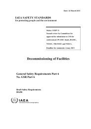
This publication is not longer validPlease see http://www-ns.iaea.org/standards/F low within con fin ed aqu ifers o c c u r s through the en tire depthof the porous stratum and there is no partially saturated zone c o m parable with the unconfined aquifer. In tercon n ection betw een con fined aquifers may be investigated by chem ical or tem perature com p arison s, natural tritium concentrations or pumping tests, but ca remust always be taken to ensure that the standpipes or m easuringp rob es are adequately sea led and do not th em selv es con tribu te toc r o s s -flo w con n n ection s. E stim a tes o f ground w ater flow in deepconfined aquifers are usually based on cla ssica l pumping tests wherenum erous conditions are assum ed. F or instance in pumping a w ell,the system is subjected to a different o rd er of magnitude in gradientand flow ra tes that m ay not be ex trapolativ e to n orm a l con d ition s.The introduction of sodium flu orescein into deep aquifers has shownthat longitudinal d isp ersion m ay be v ery pronounced, p articu la rlywith high flow rates (100 m /d a y ), and that the fastest stream lin e ofw ater may be th ree tim es the com puted average value [14],Deep g eological form ation s, below the horizons of aquifers, arereg ion s of in te re st fo r d isp o sa ls ow ing to th eir isola tio n fr o m theb iosp h ere. Outstanding, fo r its apparent su itability as a deep r e pository for w aste, is the m assive deposit of rock salt f?-9, 30]. E xp erien ce in salt m ining has dem on strated the stru ctu ra l su itabilityo f this m aterial w here la rg e cavern s have been form ed at depths of300 m without p ercep tible deform ation of the supporting salt p illa rs.Of particu la r sig n ifican ce is the fa ct that such form ation s are ch ara cte ristica lly fre e from ground w ater and n orm al m igration p rob lem s would th erefore not be m et.M ost rock form ations, however dry and seem ingly im perm eable,contain som e entrained water. In a form ation of m assive crystallinerock , below 300 m etres of unconsolidated sedim ents, the behaviourand re sid e n ce tim e o f the entrained w ater was studied to exam inew hether it was p o ssib le to store h ig h -le v e l liquid w astes in vaultsengineered in the rock by mining [31]. P erm eability tests on packedsections of w ells produced w ater-level changes in observation w ells;and it was subsequently deduced that the stru ctu re of the ro ck wastra v ersed by a wide network of hair*-like cra ck s interconnecting theentire entrained water into one hydraulic system . By assuming re a sonable values fo r the p orosity, which varies typically between 0. 1%and 6% in such m etam orphic rock , and com bining the m easu red hydrau lic gradient and p erm ea b ility , it was p red icted that the w aterm oved at 50 c m /y e a r through sound ro ck and 220 c m /y e a r throughfra ctu red ro ck . H ow ever, an independent ch eck by estim ating r e 20
This publication is not longer validPlease see http://www-ns.iaea.org/standards/ch arge into the form ation w here it ou tcrop p ed at the su rfa ce in d icated the flow to be only 0. 6 c m /y e a r . In this instance it was p o s sible to estim ate the age of the entrained water from sm all quantitiesof helium detected in solution. Since the helium was probably form edby the a lp h a -d eca y o f uranium and th oriu m , p resen t as tr a c em in era ls, it was con clu ded fro m the p rop ortion s p resen t that thewater had been resident in the form ation fo r 5X10⁵ y ea rs. The p re lim inary evaluation showed that if liquid wastes w ere introduced intosp ecially prepared cavern s in this rock , any potential hazard wouldbe extrem ely low .IV.MODES OF RELEASE(1) Liquid wastesL iquid w astes m ay be in trod u ced into the ground eith er at thesurface or by injection into deep p re -sele cte d form ations. Introductionat the su rface is sim p ler, and is done by a variety o f m ethods,o f w hich the le a st sop h istica ted is to d isch a rg e liquid d ir e c tly intoa rtificia l ponds as at H anford. T h is is a good exam p le o f su rfa cedisposal into deep deposits where the ground water lies at great depth(60 m) and the intervening zone of partially saturated soil is the prin cipal ion-exchange column for extracting radionuclides.At Oak Ridge ponds have been form ed in open excavations in theunderlying sh ale, the p ercola tion being lim ited to the in terfissu ra lzones and crack s within the shale. To reduce contamination to w ildlife, w ire netting has been in stalled over the ponds at the SavannahR iver Plant, and at Chalk R iver the same object is achieved by fillingthe pits with p ebbles. H ere the rate of d isch a rg e is con tro lle d toensure that the free water surface rem ains covered by stones. Theseare ex a m p les o f su rfa ce d isp o sa l into sh allow d ep osits w h ere thebases o f the pits lie only a few m etres above the w ater table. Manyo f the radion u clid es rem ain in the unsaturated zone and the oth ersare sorb ed within the saturated zone, w here they m igra te h o riz o n tally with the ground w ater but at a fra ction of its speed.Y et a fu rth er m easu re of su rfa ce p rotection is a fford ed if thea g g re g a te -fille d pits o r r e s e r v o ir s are th em selves bu ried beneaththe soil. This procedu re is ca rried out both at Hanford and Oak Ridge21
This publication is not longer validPlease see http://www-ns.iaea.org/standards/where the waste is piped to "c r ib s " , which may be covered trenchesor buried wooden boxes with open bases.At the National R esearch T esting Station both shallow and deepdisp osals have been p ra ctised fo r severa l yea rs [8], In the shallowdisposals lo w -le v e l effluents have been discharged into a ponded excavationabove deep dry alluvial sed im en ts, w h ereas the deep d isposalshave been introduced through a borehole extending 50 m belowthe water table, in basalt, at a depth of 200 m. At Grants, New M exico,thousands o f litre s o f lo w -le v e l w astes originatin g fro m a uraniumm ill are disch arged daily into a sandstone stratum 315-450 m belowthe su rfa ce. An im p erm eable clay b a r r ie r , 100 m thick, o v e rlie sthe sandstone, preventing any translocation of wastes into the potablew ater-b ea rin g strata above. M ore details of such operational p r o cedures are given in Appendix III.The size o f suitable fa cilitie s fo r introducing w aste w ater intothe ground depends on the volum e of waste, its chem ical com position,and the infiltration rate of the p rop osed form ation. The infiltrationrate m ay be difficu lt to a ssess becau se the dynam ics of infiltrationchange with tim e. During initial flow into nom inal dry soil there isa high capillary p ressu re that provides high potential energy gradientswith u su ally sh ort flow g e o m e trie s . T his re su lts in a highin itial rate o f in filtration . A s tim e p a sses the flow g e o m e trie s,i. e. wetted volu m e, b e co m e m uch la r g e r and cau se lo w e r en erg ygradients and a dim inishing rate of infiltration . Coupled with this,a red u ction in tra n sm issib ility m ay be caused by the dep osition ofsuspended fin es, the settlem en t of co llo id s o r the grow th o f algaeand b a cteria l slim e s. In som e ca ses efforts m ay be made to m aintainthe hydraulic ch a ra cteristics by p rio r filtration o r chlorination.A s an exam ple [8] of dim inishing in filtration the pond at theNational R eactor T estin g Station had an original filtration rate of560 litre s/m 2 day through the bed of the pit. During the first 5 y ea rs'operation , in which it a ccep ted rou ghly 3 X 10⁸ lit r e s /y e a r , the in filtra tion gradually dim inished, establish in g a m ean value of400 litre s/m 2 day for this period. But in the following 4-year period,in which the acceptance in crea sed to 7 X 10⁸ litr e s /y e a r , the rate ofinfiltration dim inished further to 250 lit r e s /m 2 day.Other experien ce in shallow liquid disposal [32J has shown thatpits excavated in suitable sands can accep t, fo r long p eriod s, low -le v e l active w aters p rovid ed that they are fre e fro m acids o r co m -plexing agents, and have passed through appropriate settlement tanksb e fo re d isch a rg e. R em aining c o llo id s are d ep osited on the bed o f22
This publication is not longer validPlease see http://www-ns.iaea.org/standards/the pit and with tim e form an additional layer of ion-exchange mediumthat extracts a large proportion of the radiocations from subsequentinfiltration. It is thus a partially com pensating com plication that willeventually reduce the infiltration rate to unacceptably low lev els, butduring this p r o c e s s new d ep osits tend to retain m any o f the r a d io cations on the b ase o f the pit.The usual backw ashing and clean sing of a sand filte r bed [5] isnot n orm ally p ossib le in the base of an infiltration pit. Plugging o fthe soil may also occu r through peptization, in which there is ch em ical interaction between the water and soil. Peptization has in som eca ses been alleviated by adding calciu m salts to the w ater, but onlyat the expense of low erin g the retention capacity o f the s o il fo rstrontium ions.T h ere have been s e v e r a l c a s e s w h ere con cen tra ted solu tion shave been d elib era tely o r a ccid en ta lly in trod u ced into the s o il andth ese have serv e d as an in d ica tor of the p o ssib le re su lts that m aybe anticipated elsew here. At Chalk R iver three separate single liquidd isp osa ls o f w aste solu tion s high in salt content, one o f w hich wasstrongly acid, w ere poured without treatm ent d irectly into holes duga few m etres above ground water in shallow sands.The m igration s after 10 yea rs w ere accu rately m apped (anexam ple is shown in F ig. 5) and th eir future m ovem ent was predictedFig. 5C ross-section showing m igration and longitudinal dispersionbetw een a disposal pit and an "area o f em ergen ce" in a swamp.fo r the next century [27, 33]. H ere, although the underground flow -paths w ere fa irly sh ort (600 m and 1000 m ), the sorp tion ca p a cityof the sands coupled with the longitudinal dispersion ensures that theultim ate rele a se of stro n tiu m -90 into su rfa ce w aters w ill be below23
This publication is not longer validPlease see http://www-ns.iaea.org/standards/current M P C W values. If, however, such disposals had been carriedout in the sands at M ol or B rookhaven the retention o f stron iu m -90would have been m uch low er and the hazard unacceptably high.If the w aste is in jected into deep confined aqu ifers the resu ltsare sim ila r except that the w astes are con cen trated in the annulusof soil surrounding the boreh ole, the screen ed portion of which p re sents a sm all c r o s s -s e c tio n . The infiltration speeds are th ereforecorresp on d in g ly h igh er and any ten den cy to plug is ch a ra cte riz e dim m ediately by higher in jection p re ssu re s. It is obvious th ereforethat the useful w orking life of such liquid ground d isp osa l fa cilitie sdepends, in gen eral, d irectly on the quality o f the disch arged fluid.Experim ents have been ca rried out to inject waste solutions intoa confined aquifer in such a way that the solution, instead of spreadingout into a d iffu se plu m e, is con cen trated in a lim ited volu m e.The method is a m odification of an o il-w e ll p rocedure in the U. S. A.w hereby waste is in jected into an exhausted oil stratum . H ere thera d ioa ctiv e solu tion was experim en ta lly in trod u ced into a cen tra lw ell and ground w ater was pumped sim ultaneously from fou r r e lie fw ells disposed sy m m etrically around it. The arrangem ent of w ellsand pumps rela tive to the strata in jected is shown in F ig. 6a. Theobject was to rem ove m ost of the ground water within the boundary ofthe peripheral w ells and replace it with the solution in a manner lik ely to ensure good con trol and confinem ent of the w aste. In this waya continuous flow was establish ed producin g an accum ulation ofsorbed, radionuclides on the soil until the zone was "exhausted"; atthis stage breakthrough would be im m inent, with contam inants appearing in a r e lie f w ell (F ig . 7). A flow net [34 J, shown in F ig. 6b,in d icates the pattern o f u nderground flow in an id ea lized situationw h ere th ere is u n iform p erm eability and no natural ground w aterm ovem ent. Sim ilar field experim ents in the C zechoslovak SocialistRepublic are being extended to in ject sludges of variou s v is co s itie sunder the im petus o f high lo ca l p ie zom e tric gradients [35].E xperim ental deep perm anent d isp osa ls have been ca rrie d outat Oak Ridge [36] using the hydrofracturing technique, where a largehydrostatic p ressu re is applied down a boreh ole into a selected h orizon. The pressure causes the stratum to fracture along its beddingplane, raising the entire overburden by a few m illim etres m easuredat the su rface. A cem en t-cla y grout, liquefied with the aqueousradioactive waste, m ay then be in jected under the maintained p r e s sure and forced into the cre v ice , where it rem ains to set and harden.In this way the w aste m ay b e im m obilized in a wide la m in a r sheet24
This publication is not longer validPlease see http://www-ns.iaea.org/standards/RELIEF WELLWELL-mFig. 6aLayout o f equipment for injecting waste into a central w elland sim ultaneously pumping water from four relief wells.thin enough to dissipate any se lf-h ea t generated, and the proced u remay be repeated several tim es in one boring by stacking the laminaeat p re -sele cte d horizons above each other. Several waste injectionshave been su ccessfu lly com pleted, but the theory of hydrofracturinghas long been a con troversial subject in the petroleum industry, whichis fraught with num erous p roblem s of rock m echanics. M ost of thelo c a l p rob lem s have now been o v e rco m e at Oak R idge, w here it isb elieved that the m ethod m ay have potential fo r wide application inthe d isp osa l of m od erately h ig h -le v e l w astes.A lm ost all r o c k strata fra ctu re under p r e s s u r e s betw een 0. 23and 0. 41 k g /c m 2 p er m etre o f depth (1. 0 - 1. 8 lb /in 2 p e r ft depth),but if large volum es of liquids are to be disposed of, fracturing alonew ill not create an adequate r e s e rv o ir [37], Only natural porosity ina ro ck form ation p rovid es the n e cessa ry r e s e r v o ir ca p acity. F or25
This publication is not longer validPlease see http://www-ns.iaea.org/standards/Fig. 6bFlow net for inverted 5-spot system with 2. 5°Jo o f total flowconducted betw een any two adjacent solid streamlines.low-pressure operation the greatest single hazard to successful disposalis the accidental reduction of permeability in the annulus ofthe formation surrounding the bore. It may be caused by suspendedsolids in the disposal liquid or by chemical incompatibility betweenthe injected waste and the rock or the naturally resident fluids. Suspendedsolids do not usually enter a rock formation but cling to theface of the injection area,creating an impermeable blanket. Thismay be dispersed by acidizing or hydraulic fracturing, but fractur-26
This publication is not longer validPlease see http://www-ns.iaea.org/standards/INJECTIONWELLRELIEFWELLFEET„__________________HUNDREDS OE J iE E I___________________________ _ 1Fig. 7Radial m igration o f radionuclides from in jection w ell towards relie f wells.D ifferential sorptive characteristics causes separation betw een nuclides.ing works only if the permeability has been so reduced that it willsustain the necessary pressures.Provided that the waste solution and the formation are compatible,other desirable criteria are that the reservoir be preferably madeof sandstone, water-saturated, and of sufficient areal extent thatthe injected fluids may flow at low velocities from the bore to displaceand compress the formation fluid. It is essential that the overlyingstrata permit the w ell-casing to be cemented completelythroughout its length and that they have low vertical permeability sothat there is no migration of waste solution upwards in the surroundingannulus nor intercommunication with fluids in superimposedformations.The examination of salt formations has been promoted becauseof their abundance and broad distribution [38], because they are inherentlydry and because rock salt has unusually attractive properties.It has a compressive strength similar to that of concrete blitunlike concrete and most other common rocks it flows plasticallywhen subjected to high stress concentrations and in so doing relieves27
This publication is not longer validPlease see http://www-ns.iaea.org/standards/the stress. Owing to this plastic behaviour it is essentially impermeablesince any cracks that may develop tend to be self-healing.Another attractive feature of rock salt is that its thermal conductivityis higher than that of most rocks, so it is better suited to dissipateheat generated by radioactive waste. Because of its chemical andphysical homogeneity it is dissimilar from all other soils althoughthe bedded deposits frequently contain interbeds of shale with a higherpermeability; it is nevertheless considered essentially as a storagemedium.In investigating its suitability for high-level liquid storage, experimentswere conducted in which solutions, chemically similarto the waste, were introduced into 16 m3 pits in the floor of a saltcavern (Fig. 8a) [39]. Electrical heating was installed to simulatethat of the actual waste, causing the solution temperature to increaseover a period of one month until equilibrium was achieved (50°C)(Fig. 8b). From these results the in-situ thermal conductivity anddiffusibility were measured and found to agree, within 10-20%, withlaboratory results on single crystals.A complication with intensely radioactive aqueous solutionsarises from their instability under high radiation. Aqueous solutionsare radiolytically decomposed, producing a hazardous mixture ofhydrogen and oxygen, and pressures of several atmospheres maydevelop. It is probably not feasible to expect salt formations to containsuch pressures for long periods. Laboratory irradiation experimentshave shown that radiolytic stability may be assured fordoses below 109 rad if the waste solution is introduced into granulesof crushed salt and allowed to permeate the interstices without forminga free surface above. For doses approaching 109 rad a liquidphase forms over the salt accompanied by a build-up of pressure.The formation of vapour and gases may also cause a hazard to storage.A serious problem is caused by the interaction between the nitratesof the hot radioactive solution and the chloride in the salt, whichtogether form a highly corrosive condition in the vapour space above.Acid waste produces NOC1, C 02 and oxides of nitrogen at temperaturesabove 50°C but this effect may be avoided if the acidity is r e duced to below 4M and the temperature maintained below 60°C.In liquid storage, isolation is best assured by introducing thesolution into specially prepared chambers in the salt, but at presentnumerous difficulties remain. In addition to the corrosion and offgasproduction, the self-heating problem is assuming greater im portance because it has increased by at least an order of magnitude28
This publication is not longer validPlease see http://www-ns.iaea.org/standards/Fig. 8aExperimental disposals, below pyramid shaped covers,in Carey Salt M ine, Hutchison, Kansas, USA.Average temperature rise in waste.since the Oak Ridge experiments, as a result of higher fuel burn-up.It is believed that the combination of self-heating and the density differencebetween the solution and the salt could result in an upward29
This publication is not longer validPlease see http://www-ns.iaea.org/standards/migration of a "waste bubble". In view of the economics of transportingwaste, the operation of the mine, and the extensive researchon the disposal of solidified high-level wastes, it seems likely thatsolid rather than liquid wastes will feature in any development ofsalt deposits.Experiments have been conducted with high-level solid wastesby placing them in suitably sized holes in the floor of a salt cavernand backfilling with crushed salt for shielding. The problems aresimilar to those for the liquid wastes except that the temperaturerise may be much higher and there is no production of off-gases. Thelimitation is set by the maximum temperature that the salt can withstand,which varies from formation to formation. Contained in thesalt there may be numerous small inclusions of water that explodeviolently when the temperature reaches a certain value (typically250-350°C). Steam is released and the shattered debris form s amedium of lower thermal conductivity than the homogeneous parentmaterial. The compressive strength of salt is unimpaired by dosesof radiation below 108 but above that value there is some reduction.For a 2-year cooled calcined waste this dose may accumulatewithin a radius of 30 cm but, since the floor of the cavity does notsupport the load of the overburden and the support pillars are beyondthe local radiation fields, the structural stability of the cavern isreasonably assured.(2) Solid disposalsIn the routine monitoring of solid radioactive waste, materialsare usually segregated according to their activity levels: those thatrequire shielding, those that are contaminated with alpha-emittingnuclides, and those that require no special shielding. It is in thislast category that large volumes of contaminated trash and garbageare being produced at an ever-increasing number of sites around theworld; its disposal is a problem for most nuclear establishments[40, 41, 42]. The varied nature of this material, which may rangefrom paper to glassware, rubber gloves, wooden boxes or metal pipe,may require additional handling if, for instance, physical segregationis needed to permit baling or incineration. For this reasonshallow land burial is frequently adopted because of its simplicity;it may sometimes be wasteful in consuming large areas of land butit does allow the piecemeal direct disposal of miscellaneous wastes.The simplest disposal procedure is similar to that used in municipal30
This publication is not longer validPlease see http://www-ns.iaea.org/standards/garbage dumps where the waste is tipped over the edge^of a shortslope to accumulate and assume its natural angle of repose. Withcontinued tipping the sloping face of garbage advances and the exposedcrest is covered with soil and consolidated to form an accessfor vehicles bringing more waste. Although the simplicity and cheapnessof this method is attractive, the disadvantages are fairly obvious.There is the danger of containers or bagged waste rupturing whenthey are tipped; this would spread contamination down the face ofthe slope, possibly overspilling beyond the base. The resulting exposureto wind and rain is particularly undesirable if there is thepossibility of contaminated surface water collecting at the base ofthe slope and thus spreading activity in the resulting ru n -off.Shallow ground disposal is more safely carried out by tippingthe waste into trenches excavated in soil known to be free fromwaterlogging and nominally dry under typical conditions (Fig. 9). Theadvantage of this over the "tip and fill method" is that contaminatedrain-water is automatically directed underground and the spread ofsurface contamination is minimal. The packaging of this m iscellaneousmaterial is generally only sufficient to prevent the spreadof particulate contamination while it is being transported from thelaboratory or workshop to the disposal ground. Paper or plasticbags and sheeting are usually used so that after tipping and consolidationthe waste is only nominally protected.One of the recurring problems is to assess satisfactorily themagnitude of this type of disposal without emptying the contents ofeach bag and subjecting articles to laboratory scrutiny. Owing tothe nature of the materials and the variety of radioisotopes with whichthey are contaminated, it is impossible, at present, to measure accuratelythe number of curies and the specific radionuclides presentin a disposal. In this respect, precise estimation of the magnitudeof solid disposals is much more difficult than for liquid disposals.A common method of assessing the activity in a packaged disposalis to measure the radiation field with a portable counter held at astandard distance from the bag or in contact with it. Each establishmenthas its own interpretation of these results, based on the typicalspectrum of contaminants present in their waste. In this way theirradiation readings are converted empirically to "nominal curies"of activity in the disposals.When low-level waste is buried without containment, the principleis accepted implicitly that some contamination will be leachedfrom the solids and carried away by the percolation from rainfall.31
This publication is not longer validPlease see http://www-ns.iaea.org/standards/Fig. 9Trench excavated in sand for typical lo w -le v e l solid waste.The disposal is thus a planned continuous release of radionuclidesinto the environment at a rate dependent upon the infiltration and theleachability of the solid material. If the climate is wet and consistentleaching may reasonably be anticipated, quite obviously the sorptionby the soils determines whether the migration will be held withinacceptable limits or whether the site will be unsuitable. The acceptabilityof the potential exposure therefore depends on the ionexchangecharacteristics of the soil for the "biologically hazardousradiocations", the rate of deposition of contaminated waste, and theresultant rate of migration. In particular, one would expect the migrationof strontium-90 to be in the order of metres per year ratherthan tens of m etres per year. At Savannah River it has been demonstrated[43] that the leaching potential may be reduced by coveringthe local area, containing the buried waste, with an impermeablemembrane or "umbrella". In a full-scale experiment (Fig. 10) the32
This publication is not longer validPlease see http://www-ns.iaea.org/standards/Test area 15 m X 15 m surrounded by 8 m deep trenchand sprayed with bentonite "um brella" on top and sides.ground surface of a selected area was sprayed with clay to form themembrane. This was covered with more soil to arrest drying,shrinkage and cracking, and infiltration measurements beneath thearea were compared with those from the surroundings. Resultsshowed a pronounced increase in run-off and reduction in infiltrationthat would reduce further the likelihood of any migration.Solid wastes of higher activity must be isolated from naturalwater and contained in structures [44] that may be expected to retaintheir integrity for many decades. If they are made from concrete,which has so far proved to be one of the more suitable and economicalmaterials, then adequate precautions should be taken to ensure thatthey will withstand erosion or chemical decomposition from naturalwaters. In addition, they must be made watertight and strong enoughto resist stresses caused by settlement of the foundation. These
This publication is not longer validPlease see http://www-ns.iaea.org/standards/types of underground containers are also suitable for storing thesmall quantities of radioactive liquids, such as solvents, that defynormal liquid treatment processes and must be stored indefinitely insealed bottles. When containment is practised, it is important thatwater is excluded from the container while it is being filled so thatno erosion may start from the inside. To ensure that there are novoids in the waste, concrete or sand may be poured in before the containeris capped and.sealed. Thus settlement of the waste itself isforestalled, residual water is incorporated or absorbed, and differentialstresses are avoided in the resistance against outside earthpressures.Between the extremes of complete containment and calculatedslow release from low -level solid wastes, there are intermediateprocedures that are often suitable. For instance, solid equipmentmay be subjected to a decontamination procedure to remove mostof the radioactivity, and the residual surface contaminants may thenbe sealed with paint or lacquer. Preliminary pre-treatment of thistype reduces leaching from objects buried without containment bydenying access of ground water to the contaminated surfaces. Theprinciple may be extended to sludges where individual particles arecoated with an insoluble film such as asphalt [15, 45]. Here the process,which is described in greater detail in Appendix I, extends theinsolubilization beyond sludges and ash residues to concentrates fromevaporation that are corrosive and have high salt contents. Particularemphasis is laid on the ability of the coating material to withstanddegradation when subjected to prolonged irradiation from the concentrates.The final disposal of this type of material may be directlyto the soil, but with asphalt it is convenient to allow the mixtureof waste and asphalt to solidify in drums at the mixing site andlater transport the drum and contents for disposal.Pre-treatment methods for concentrated waste solutions of highsolids content are more appropriately dealt with under the separatesubject of solidifying high-level wastes. These methods include calcinationand conversion into ceramics [46] and glasses, but at presentnone of these solidified products is routinely disposed of intothe ground, although experimental burials have indicated that thelow leachability expected from laboratory measurements is reproduciblein the soil [47]. These products appear to release radiocontaminantsunder conditions of constant saturation, at acceptablylow rates, corresponding to a surface erosion of roughly 10"8 g/cm2 day.34
This publication is not longer validPlease see http://www-ns.iaea.org/standards/V. EVALUATION OF SITES, AND METHODSOF GROUND DISPOSAL(1) Potential exposuresThe use of the ground for disposal operations is based on twofundamental properties. First, the minerals from which the subsoilsare composed generally have a marked sorption capacity formost uranium fission products as well as for many other radioisotopes.Secondly, the mass of soil covering a disposal provides goodradiation shielding and permanent physical protection to people aboveground.Ground disposal of radioactive waste is a method by which thethe waste may be disposed in such a way as to release radioactivityslowly into the environment. If the rate of release from a waste isexpected to be unacceptably high, the waste is put into a container.This is merely an additional safeguard to postpone the eventual releaseof contaminants until the container eventually fails through corrosionor erosion, when it is anticipated that the radionuclides inthe stored material will have decayed to sufficiently low levels topermit their slow release into the soil. In such a case the actionmay be considered to have been permanent disposal; but if the activityremains high at the end of the estimated useful life of the container,the action is but temporary storage.Where large volumes of slightly radioactive effluents are produced,they may possibly be discharged directly into a river; theturbulent diffusion and dilution would be relied on to reduce the contaminantconcentrations to acceptable levels downstream. It may,however, be possible to discharge the effluent into permeable soilnearby, where the water will infiltrate underground before emerginginto the river. Such practices have a special advantage if occasionallyhigh transient releases should occur, perhaps through errors inprocessing or control. When the hazard level is inherently low or oflimited significance, the soil in the line of underground flow willserve to disperse and delay such transients. The seepage concentrationsissuing from soil to river would, in consequence, be more uniform,even with those radionuclides that experience little delay dueto exchange.In the normal case of ground disposal by shallow land burial thedisposal site is remote from the lake, reservoir or river drainingthe catchment and the intervening path may be tortuous, lying partly35
This publication is not longer validPlease see http://www-ns.iaea.org/standards/below ground and partly above. In the underground section a longenforced residence with restricted flow rates and sorption reactionsprovides overwhelmingly the delay needed before release. Once thecontaminants emerge in surface water they are subjected to largedilution and comparatively rapid transport, but reconcentration ofspecific radionuclides may be expected in the aquatic biota and onminerals in suspension and on bed deposits [48], At the end of thisflow-path the residual concentration of contaminants has to be belowthe maximum permissible concentrations in water and foodstuffs forconsumption by the general public.The importance of the type of sub-soil, the proximity to streams,depth to water-table, permeability, etc. have already been emphasized,but simple procedures on the site can do much to restrict aninitial spread of contamination by wind, rain or surface water. Inparticular, elementary precautions to stop surface water flowing intoa trench or container, or temporary roofing to prevent rain or snowfrom coming into contact with the waste, can greatly reduce any hazard.It is generally true to say that the possibility of spreading contaminationis greatest when the disposal facility is being filled; ifit is to be capped or sealed there is normally an immediate reductionin the potential hazard.An important requirement in the choice of a site for ground disposals[49] and in particular for shallow land burial is that the areabe reserved exclusively thereafter for waste disposal. It must beadequately fenced, must have no alternative use, and its presencemay well inhibit the development of surrounding areas. The finalityof the choice is so absolute that complete confidence is essential thattlie area would be required for no other conceivable purpose and wouldbe solely a ''restricted area’1. It is conceivable that mineral r e sources themselves could become contaminated by radioactivity butwith shallow disposal operations the concentration levels would beunlikely to inhibit mineral recovery if it was commercially economical.This situation is more likely to arise where liquid wastesare injected into deep formations and it indicates that deep disposalsites should be chosen only after a careful investigation of neighbouringstrata for potentially exploitable minerals.The evaluation of a proposed site must include a prediction ofthe probable stability of the existing ground water equilibrium. Onemay assume that there exists in the soil an equilibrium [50] in thereaction between the radioisotopes in the liquid and in the solid phase.The equilibrium is influenced by the mineralogical, chemical and36
This publication is not longer validPlease see http://www-ns.iaea.org/standards/physical environment, and equilibrium conditions may be attainedmore or less quickly. Accordingly, one must take into account thatany later changes in the characteristics of the contaminated aquifer,caused for instance by the introduction of a new waste of differentcomposition, the building of a dam, the use of a large new productionwell or the tapping of a spring, can introduce a new conditionthat may increase or decrease rate of movement and change rate anddirection of underground flow. The evaluation should also includethe probability of natural occurrences, -such as earthquakes orchanges in erosion level with time, and how these may affect the behaviourof the radioisotopes in the disposal area. Establishmentsintending to m a:e planned disposals should consider these questionsin consultation with earth scientists when examining a prospectivedisposal area.(2) Site evaluationTo summarize the significant natural phenomena affecting grounddisposal, Table I has been assembled. It embodies the factors ofclimate, hydrology, geology and geography as well as the conditionof the waste, and indicates which characteristics are, in general,favourable and which are unfavourable. Some of these factors (e. g.pH of the waste) may appear in either column according to the characteristicsof the environment. However, the list is intended torepresent the more common cases.Obviously the factors listed must be considered individuallysince certain combinations of so-called favourable features are inconsistentwith naturally occurring situations. They are thereforean indication only of the qualities generally found to be favourable,but many exceptions are possible. For instance, the slow groundwater movement noted as a favourable hydrological feature may bedue either to a low permeability or a low hydraulic gradient. If liquiddisposal were anticipated, conditions of low permeability wouldbe quite unsuitable, since the effluent would be unable to percolatefast enough into the soil. If the low hydraulic gradient were presentin a highly transmissive medium - a normal condition - then theboundary conditions of the aquifer would control the extent of anydisturbance to the equilibrium through the introduction of largevolumes of effluent. If the aquifer were shallow or of limited arealextent, rapid sub-surface flow could be anticipated.37
This publication is not longer validPlease see http://www-ns.iaea.org/standards/TABLE IASSESSMENT OF GROUND DISPOSAL FACTORSFactorsFavourablecharacteristicsUnfavourablecharacteristicsPhysical state o f waste Solids Liquids; sludges.C hem ical com position o f wasteA lk alin e; neutral;low salt.A c id ; high salt.R adiochem ical com position o fwastePresence o f short-livednuclides.Presence o f (a) lon g -liv ednuclides, (b) anionicspecies.Geographical situation Low p recip itation ;rem ote from openwater sources;rem ote frompopulation centres.High p recip itation ;close to rivers, lakes;close to populationcentres.G eology (geochem istry)Uniform unconsolidatedm aterials;high sorptive s o il;low soluble ca lciu mcontent.Fissured rocks;inert m aterials;high content o f ca lciu mor other soluble salts.Hydrology Deep water ta b le ;slow -m oving groundwater; slow ionm igration; longpath to point o fdischarge.Shallow water ta b le ;fast ground w ater;fast ion m igration;short underground flowpath.Another example may be where the-"highly sorptive materials",classified as "favourable geological" features, are present in theform of clay. This material has the other favourable characteristicof low flow rate, in fact so low that it is effectively impermeable.In such a case the massive ion exchange potential of the deposits isnot used since they remain largely inaccessible to the bulk of radioactiveliquid. Where solid radioactive waste is deposited in opentrenches excavated in clay, water slowly accumulates, saturates the38
This publication is not longer validPlease see http://www-ns.iaea.org/standards/waste and, unless protected from the ingress of surface water, eventuallyoverflows, spreading contamination above ground.The preferred conditions lie somewhere between the extremes,i. e. where the soil is coarse enough and of low enough clay contentto permit easy percolation of water, yet of such texture that an adequateadmixture of clay mineral is available for exchange with theradiocations.(3) Choice of shallow or deep disposalThe choice between shallow or deep disposal cannot be generalizedand each proposal has to be considered on its merits. It is perhapsgenerally acknowledged that the disposal of radioactive wasteinto deep formations is, in principle, preferable to shallow disposal,particularly for liquids. If the solutions can be injected into formationswell below any potential aquifers, their permanent isolation isreasonably assured, and as a result it is probable that wastes of farhigher activity levels than those judged prudent for shallow disposalmight be introduced. But the procedure and the investment involvedmust be examined against the comparative potential hazards resultingfrom simpler procedures.The shallow disposal of liquids into sites where there is a greatdepth of dry soil is another method which may ultimately introducewaste into deep formations, but unlike the example given in the previousparagraph, the solutions are disposed above rather than belowthe aquifer. Such terrain, where the water table is at great depth,often occurs in arid regions where recharge is negligible. The uncertaintiesabout the vertical migration rates and the attendant difficultiesin monitoring and measurement make difficult the accurateprediction of migration rates and the probable potential hazard toneighbouring water supplies.Although deep disposals have much to commend them, shallowground disposal may have attractions even though the local watersupplies and the environment generally seem susceptible to immediatehazard. The choice of a site and the depth of disposal may well begoverned by the ability to collect adequate geological and hydrologicaldata. If the sub-soil is known or shown to be regular and homogeneousa few exploratory borings and sampling may be adequate. But usuallysuch a picture is an over-simplification of heterogeneous depositswhose physical characteristics vary much more than their chemicalcharacteristics. In these circumstances the investigator must be39
This publication is not longer validPlease see http://www-ns.iaea.org/standards/prepared to estimate the importance of local heterogeneity and toestablish how representative are the results from any selectedboring.The measurement of most of the necessary fundamental data canbe carried, out for shallow formations where migration will be limitedto depths probably less than 25 m. Under these conditions, migrationscan be predicted and,if necessary, experiments conducted withincremental releases of radioactive solutions to check the predictionsquantitatively. The means of following the track of migration lie inthe numerous shallow sampling techniques simplified, if necessary,by prior introduction of non-radioactive tracers into the groundwater.The contrasting philosophies of shallow and deep disposals mustbe clearly understood. Shallow disposal methods envisage a slowcontinuous release into the environment that can be monitored r e gularly. The delay caused by migration underground provides adequatewarning if hazardous quantities of radio-contaminants havebeen erroneously introduced into the soil. The condition can probablybe corrected by pumping the contaminated water to the surfaceand treating it by other methods [51 J. But the normal condition envisagedis that the rate of seepage and the corresponding concentrationsof pollutants do not cause the maximum permissible concentrationsto be exceeded in the immediate body of water that they enter.This condition would be expected to last throughout several decades,during which the decayed contaminants would be eventually releasedto surface waters.Deep disposal methods, by contrast, do not envisage any r e lease when they are introduced into a permanent repository belowknown potable ground water bodies. The installation of bores suitablefor injection would be accompanied by an extensive examinationof all formations intersected, particularly for their permeability.However, the need for exact quantitative data decreases with depthand increasing water salinity, especially if the hydraulic head onthe deeper aquifer is lower than in the shallow potable aquifer. Evenwhen large volumes of low-level waste are introduced into a porousformation, migration from this reservoir to higher strata is thusunlikely although the degree of confidence depends on the activitylevel of the disposed solution. If there is a horizontal migrationthere is at present no simple way of tracking it, but the resultanthazard is probably insignificant. The method probably lends itselfmost economically to the adaptation of formations previously tappedfor extracting other naturally occurring fluids.40
This publication is not longer validPlease see http://www-ns.iaea.org/standards/Where the stratum to be used for deep disposal lies above anaquifer, some migration is likely, but measurement and control overthe migration is not comparable with the control possible for shallowdisposals.(4) The small-scale disposal of solid wastesAll the descriptive details have so far been related to la rgescaledisposal operations, from which most of the current experiencehas been derived. Yet many cases may arise where a small producerof radioactive waste would question whether it is necessaryto embark on a large pre-operational survey or whether a curtailedinvestigation might be sufficient and more commensurate with theminimal hazard involved. With solid waste the latter premise maybe valid, and the points that have to be considered are:(a) The choice of site;(b) The environmental condition most likely to produce migration;(c) The limitation on the type of waste and how it should be contained.(a)The choice of siteIf a site is to be evaluated completely there is no alternative toa thorough examination of the geology, ground water hydrology andsoil chemistry. But since experience at many sites has shown thatthe contamination on solid waste buried in the aerated zone tends toremain stationary unless leached by water, it may be adequate to burythe waste in unsaturated soil, all necessary precautions being takento avoid rainfall infiltrating the waste. The question remains: howmay such a site be evaluated?A system has been developed [52] to assist sanitary engineerswho are frequently faced with similar problems, such as choosinga site for a septic tank system with assurance that it will not pollutenearby wells or a water supply. The geological and hydrologicalcomplexities are evident, but with limited data at hand preliminaryevaluation must be made in planning and sometimes the same dataare used even for construction.The Point-Count System provides a standard for comparing themerits of a number of sites by evaluating each with reference to fiveenvironmental factors, namely:Depth to water tableSorption41
This publication is not longer validPlease see http://www-ns.iaea.org/standards/PermeabilityWater table gradientDistance to point of use.These are composed in a point-rating chart, shown in Fig. 11,in which the conditions at a site are checked against each of the factors,and points are awarded in each category. The larger the totalWATER TABLEr----- --------- 1----- 1--------1——i------------i— ---------- r5 20 30 AO 60 100 200 300DISTANCE BELOW BASE OF DISPOSAL UNIT-mLIMESTONE | COARSE CLEAN SMALL AMOUNTS EQUAL AMOUNTSFRACTURED ROCK SAND OF CLAY IN SAND OF CLAY AND SANDI I IFINE SAND FRACTURED ROCK COARSE SANDGRADIENT3 2 1 0|------------- 1------------- 1------------------- ,------------------------------,----------------- 10 2 5 10 30 60PERCENTAGEDISTANCE0 1 2 3 4 5 10 13H --------1--------- h---------1---H— i ---------- 1----- '— i---- *— i----------- t—1----- 13 10 30 50 75 100 200 500 m 1km 2 16kmFig. 11Rating chart for radioactive waste disposal sites.On all scales the point values are indicated by the upper scale.The chart is not applicable i f m ore than 50% o f the distanceis through lim estone or fractured rock.number of points accumulated by a site, the better it is for disposalpurposes.The point-count system does not purport to be anything morethan a rough approximation and has been developed empirically fromwidespread experience in cases of well and water supply pollution.The chart shown for radioactive waste is slightly modified from thatapplied for other pollutants and should be used preferably where thesoil is granular. It should be noted that the points allotted for certainfactors are based on highly simplified concepts. For instance, the42
This publication is not longer validPlease see http://www-ns.iaea.org/standards/chart for sorption takes into account none of the selectivity of certainclay minerals for specific radionuclides; all it does is to recognizethat soils containing clay are better than those with no clay. Similarlythe points allotted for permeability are greatest (only 3) for asandy-clay soil, decreasing inversely with permeability and decreasingalso towards pure clay where there is practically no flow to promotesorption. Little significance is therefore attached to the magnitudeof permeability in sands, which may be hundreds of timesgreater than for clays. Note that those factors in the chart that domost to enhance the value of a site are: the distance down to thewater table, the sorption of the soil, and the distance to the point ofuse. When this system is used it should be realized that in such animprecise evaluation it is futile to obtain an exact value for only some 'of these factors if the precision is to be lost in the crude estimatesof the remaining factors.As an example of its use, consider the hypothetical case of asite where the base of a disposal trench is anticipated to be 3 m abovethe highest estimated ground water level (i point). The soil is a finesilty sand (S = 2, P = 2, say) and the slope on the water table isroughly 5% (1) towards a perennial stream 150 m away (3). Totalpoints = 8j. This result by itself is not meaningful, but when a seriesof prospective sites are compared those potentially the more suitablemay be selected for later judgement in the light of more detailed investigation.(b)Probable conditions likely to produce migrationIf the soil has a large clay content and is of low permeabilitythe greatest hazard will probably develop from surface water enteringthe trench and overflowing on the surface. In such material it isfrequently possible to excavate suitable trenches with almost verticalsidewalls without risk of cave-in; the soil surrounding the disposalsis thus relatively undisturbed. With such clearly defined boundariesto a disposal trench it is simple to carry out suitable precautionssuch as thoroughly compacting the filling, raising the filling profilerelative to the surroundings to divert surface run-off, and cappingthe trench. If, on the other hand, the soil is granular a hazard maydevelop from migration and the base of the trench must always beabove the saturated zone even at times of flood. Low-lying areasshould preferably be avoided and the trenches should be sited wherethere is gentle relief to the land profile. In this way run-off is en-43
This publication is not longer validPlease see http://www-ns.iaea.org/standards/couraged, although the trenches should still be capped with a flexibleimpervious material such as clay or asphalt capable of assuming themodified surface profile after the waste has settled. It is not usualto go to the added expense of providing a rigid concrete roofing forlow-level disposal trenches.The packaging is more important for the handling of waste thanfor its disposal, where minimal covering by waxed paper or plastichas sufficed at numerous disposal sites, and has resulted in negligiblemigration hazards. However, the more substantial packingssuch as drums and wooden boxes, sometimes used, have normallyreduced the voids volume by permitting the waste to be placed selectivelyand so the best use is made of the space available.(c)The type of wasteThe other feature that should be examined is the radionuclidecontent in the waste and the length of its half-life. Here it is of interestto note the proposals in the United Kingdom, where grounddisposal is practised only on a limited scale. It is suggested [53]that small quantities of waste should be permitted to be dischargedinto selected municipal refuse dumps. These dumps would be chosenwhere there was minimum risk to the contamination of water supplies.The amounts proposed are, however, very small, being less than100 /uCi per package for isotopes of half-life greater than one yearand 1 mCi per package if the half-life is less than one year. Incarrying out disposals the general limitations may be modified orexpanded to suit the kind of waste envisaged. An example of a typicalmodification is that the alpha-activity of any package should notexceed 1 mCi and that the main activity on the surface of unshieldedmaterial should not exceed 0. 1 nCi per cm2 of alpha activity or0. 75 R/h gamma radiation.Finally, it should be appreciated that waste normally destinedfor land burial includes not only low -level packages of juCi or mCicontamination, but large volumes of waste that are possibly radioactivebut generally not. Because of the expense of monitoring andsegregation it is disposed as low -level waste for convenience andthe result is that the mean level of contamination is very much lowerthan the limits given may suggest.44
This publication is not longer validPlease see http://www-ns.iaea.org/standards/VI.STANDARDS AND CONTROL TECHNIQUES(1) StandardsAny standards proposed for ground disposal are based mainlyon the primary return route to man by migration through sub-surfacewaters. The standards should be such that adequate health protectionis assured both to operating staff and to neighbouring communitiesand that all avenues of reconcentration in biological systems are recognized.The standards applied to effluent seepage concentrationsshould, in addition to meeting human requirements, be acceptablefor the subsequent re-use of the water by industry. Commercialundertakings may take water from downstream points in the hydrologicbasin; thus the residual contaminants should be within acceptableconcentrations at these water intakes. Although the limits arenot normally exacting in purity requirements, certain industries,for instance the photographic industry, are particularly sensitiveto changes in the background concentrations of radionuclides in theirwater supplies.Most problems in ground disposal are basically of a local nature.Ideally it would be useful to set contamination standards for the soil,taking into account the sorption phenomena relative to time and concentration.But because of the complex structure and inhomogeneityof most soils it is more realistic to work from the contamination levelsof the groundwater that are permissible at the point of emergence. Suchlevels can be derived from the Agency Basic <strong>Safety</strong> Standards [54]or the ICRP recommendations [55], taking into account such mattersas the use of the water, population densities, mineral resources,reconcentration in biological systems, and permissible body burden.General guidance in evaluation techniques for similar problemsis given in detail in the <strong>International</strong> <strong>Atomic</strong> <strong>Energy</strong> Agency1s Reportson "Disposal of Radioactive Wastes into Fresh Water" [56]and "Radioactive Waste Disposal into the Sea" [57].(2) ControlThe total volume of disposals to be permitted at a given siteneeds to be estimated. If the area is to be used solely for low-levelsolid waste, given reasonable soil and ground water conditions, thelimitation will probably be set by the size of the area as for any normalrefuse dump. For liquid disposals this may also be true if se45
This publication is not longer validPlease see http://www-ns.iaea.org/standards/veral disposal basins are used and insignificant migration developsbefore they are ultimately abandoned because of diminished infiltration.But it is more likely that the limit will be set by the maximumattenuation afforded by the soil before seepage into surface watersreaches the maximum permissible concentrations. The complexitiesand uncertainty involved in predicting the detailed behaviour of wastefrom laboratory experimentation encourage a more empirical approachto determine the working limits. Field experiments may bemade with tracers in the ground water and when flow rates and directionsare estimated further measurements may be made by releasingincremental amounts of typical waste and studying intensivelytheir subsequent behaviour. Such investigations would indicate whichradionuclides were the more mobile and from their biological im portance the limits would be established. This empirical approachwould be extended to predict the flow and dispersion experienced bythese pollutants and the limits of the disposals would be set accordingly.Such predictions may be possible only with liquid disposalswhere their magnitude is known with some accuracy.It is usual for an ensuing operational practice to be ultraconservativeto begin with, but as experience grows and favourableresults from environmental surveillance establish confidence in thesafety of such disposals, the limitations may be relaxed accordingly.All long-term predictions must naturally be tempered by the reservationthat they are valid only if the ground water pattern or regimeremains unchanged. Such predictions cover short periods in geologicaltime so it may be that the greatest possibility of change willcome from man-made developments that may alter the projectedpaths of radioactive migration.The control and surveillance of ground disposal operations re quires two forms of regulation: (i) Control before discharge;(ii) Surveillance and monitoring after disposal. Before the wasteis released to the soil it must be monitored or analysed to assureconformity with the accepted disposal standards. This is of outstandingimportance in all liquid disposals. The examination maybe carried out by a continuous monitoring device automaticallyscanning the flow, or it may involve sampling and analysis of batchesof waste before discharge. Special techniques are sometimes requiredto collect accurately representative samples from a batch,particularly if the waste contains two or more phases, e. g. suspendedsolids, precipitates, or globules of immiscible organic solvent. Itis quite common for most of the radioactivity to be concentrated inthe dispersed phase; this requires great care in control sampling.46
This publication is not longer validPlease see http://www-ns.iaea.org/standards/An important feature in control of ground disposal operationsis an efficient system to segregate wastes. The segregation of solutionscontaining acids, detergents or complexing agents fromlargevolumelow-level effluent can contribute significantly to the efficientground disposal of liquids by ensuring that the sorption potential ofthe soil is fully mobilized. In solid disposals also, efficient segregationcan contribute not only to the safety but also to the economyof the operation. Permanent storage bunkers are expensive and itis essential that the various types of waste are directed to their appropriatefacility. These may vary from heat-dissipating structuresor concrete containers, to open trenches, and quite obviously spaceis at a premium in the more elaborate facility.Efficient supervision before and during disposal is far more effectivein controlling the spread of contamination than any later control,which is concerned almost entirely with environmental monitoring(3) Moni toringAll ground disposal operations, whether liquid or solid, haveto be carried out under careful surveillance, and the precautionstaken before disposal - for example the pre-treatment of liquidsor solids, packaging, segregation - have to be followed by appropriateprecautionary measures after disposal. If underground m igration is anticipated the monitoring of such movement is bestachieved by the sampling and examination of ground water. Tracequantities of radioactivity, except of tritium, may be concentratedif necessary by evaporation before assay or identification. The assayof soil samples may be more troublesome; gamma-spectrometrymay be used for suitable nuclides but for pure beta-em itters thecontaminants must be leached for analysis. However, if they arepreviously known and only the count is required, soil samples maybe counted directly in an end-window counter provided that the sampleis no greater than a single layer of grains spread over the countingtray. In this way it is possible to counteract much of the attenuationdue to self-absorption by the soil, and reproducible results may beobtained for comparison against a standard previously analysed.For the monitoring to be most effective the sampling tubes orwells must be positioned to intercept and overlap the anticipated pathof migration, and unless this area is indicated by radioactivity inthe foliage of vegetation or in nearby surface waters, the positionof this will have to be determined from an examination of the water47
This publication is not longer validPlease see http://www-ns.iaea.org/standards/table profile and probably the underlying soil. Numerous points mayhave to be examined and it is often convenient to use a sampler(Fig. 12) that is easy to drive and withdraw, precise in the horizonfrom which it samples, and re-usable from site to site. In Fig. 13aand b such a sampler is shown suitable for attachment to drill rodsfor driving directly in the soil. Once the path has been found, monitoringmay be conducted either from continued water sampling orfrom direct radiation measurement by sinking dry aluminium tubesin the soil into which suitable counters may be lowered. Such arrangementscannot be recommended if beta-emitters only (e. g.strontium-90) are present but for gamma-emitting nuclides the contaminatedhorizons may be identified with precision. This methodis particularly satisfactory for monitoring the aerated zone, wherenormal water sampling methods are generally inapplicable. Soilsampling is of course possible in this zone but it is a non-repetitiveprocedure; each act of sampling disturbs the soil and the methodis therefore little used when a continuous monitoring record isneeded.Where liquid disposal is practised, routine ground water monitoring,tracer tests, and occasional soil sampling would be normalto keep a check on the progress of migration. It frequently occursthat tritium is present in liquid disposals, either from the activationof deuterium or as a product from the bombardment of lithium, whichis a corrosion inhibitor sometimes used in reactor cooling systems.Tritium can therefore be expected from the'se sources in the effluentfrom certain reactor cooling loops or in waste streams from fuelprocessing. Whereas the monitoring of migration is normally concentratedon the biologically hazardous nuclides, tritium, owing toits low hazard potential, has sometimes been overlooked. Yet theoccurrence of tritium in waste effluents provides an ideal tracer formonitoring purposes and an early indicator of the path to be followedby the slower moving radiocations [58, 59], There is thus a goodcase for monitoring for tritium at any site where liquid effluents aregenerated and routinely discharged into the soil. Often the tritiumconcentrations in the samples are high enough for them to be assayeddirectly in a liquid scintillation counter. When this is not so, thetritium concentration has to be increased by electrolytic methods ifthe same type of counter is to be used.In solid waste disposals the problems are simplified since thewater infiltrating from recharge is the only carrier of leached contaminantsand sampling devices may be installed beneath any struc-48
This publication is not longer validPlease see http://www-ns.iaea.org/standards/Water sampling in granular soil.Samples extracted by suction through plastic tube into evacuated flask.
This publication is not longer validPlease see http://www-ns.iaea.org/standards/‘^ 7Fig. 13aView, of dismantled water sampler.ture to lead what little moisture there is to one collecting basin.Fromhere it may be withdrawn, if it is within the range of suction lift, bypumping through plastic or metal tubing extending to the surface. Theadvantage of such devices is the ease with which the source of contaminationmay be identified with a particular installation. Wherelow -level waste is buried in trenches, reliance again is placed onground water sampling. Samples may be withdrawn from sm alldiametersampling wells sited close to the trenches in undisturbedsoil or from a sampling point positioned in a sump pre-form ed inthe base of a trench.A broader surveillance of the environment by monitoring water,vegetation and natural livestock is an essential check on the efficacyof the principal monitoring devices and establishes a record of backgroundradioactivity from natural effects and weapons fall-out. Theroutine collection and monitoring of water samples from any nearbystreams during base flow periods is a particularly good check onthe purity of the ground water that continuously replenishes thestream. Seasonal records of radioactivity in the foliage of local vegetationare a useful indicator of radiobiological uptake and concentrationfrom subterranean sources. But where the ground water is50
This publication is not longer validPlease see http://www-ns.iaea.org/standards/Fig. 13bCross-section through water sampler.deep and beyond the reach of the root system, no activity would befound in the foliage. Finally, a check on the dissemination of con51
This publication is not longer validPlease see http://www-ns.iaea.org/standards/taminants by rodents and other wild-life, may be carried out bysampling the species regularly and determining contamination levelsin flesh, bone and selected organs.To ensure the protection of the general public and the continuedsafety of a disposal area it must be permanently fenced and appropriatenotices must be displayed. Entry should be restricted to thosepeople operationally engaged in the area and standard monitoringprocedures of clothing and equipment should be undertaken at the exitto stop any spread of contamination outside the fence. Also accuraterecords, registered both at a central office as well as at the siteoffice, must be maintained of the whole operation. In view of thelong life of the hazard, the magnitude of each disposal must be notedand its position charted accurately relative to a prominant and permanentlandmark above ground. Such procedures are needed notonly to safeguard the present public but also to ensure the protectionof future generations who through ignorance could inadvertently reexcavatethe buried waste.(4) Accidental releaseAn additional situation arises from the large array of possiblespills, leaks or equipment failures which may cause accidental introductionof radioactive material into the ground. Normally, such anaccident would be confined to liquid wastes, although it is conceivablethat airborne contaminants, settling and subsequently leached byrainfall, could constitute a low -level introduction into the soil.It is common practice to retain high-level waste solutions intanks placed underground to take advantage of the natural shieldingoffered by the covering of soil. If such a tank develops a leak, orif a leak develops in an underground pipe-line carrying a radioactivesolution, the resulting release of radioactive material creates problemssimilar to those arising from normal liquid disposal operationsexcept that the specific activity of the solution is probably muchhigher.Steps that may be taken to prepare against accidental releaseare relatively few although where they occur at a permanent installationthe transport hazards are avoided. Here the local soil andground water conditions are known and the subsequent behaviour morepredictable.With underground storage tanks it is desirable to provide measurementdevices to detect leaks. Internally this may be in the form52
This publication is not longer validPlease see http://www-ns.iaea.org/standards/of a sensitive level gauge and externally it may be by radiation detectioninstruments either operated in adjacent boreholes or installedin lateral channels constructed beneath the tanks [60], In particularlyhazardous situations, a double-tank arrangement is used, bywhich any leakage from the inner tank is collected in the outer vesseland monitored. A tank design which provides for the rapid transferof one tank1s contents into another may prevent a large release intothe soil.After the specialized details of containment have been decided,probably the most useful preliminary studies, to prepare againstaccidental leaks, are those that will indicate beforehand the probablebehaviour of the radioactive liquid after it has escaped into the soil.Such details may normally be taken into account where an installationis planned, say, near a river. However, in other situationswhere the effects of accidental releases are less obvious, these subterraneaninvestigations must not be overlooked.To summarize the various procedures, one may say that theintroduction of radioactive materials into the soil is generally likelyto cause less pollution if the waste is in the solid than the liquid stataBut owing to the nature of solid waste it is generally not possible topredict the actual quantity of soluble radionuclides that will beleached from the waste. Liquid disposals, by contrast, may be preciselyevaluated except where there are accidental escapes, and theirintroduction will be carried out only after adequate prediction of thebehaviour of the disposals has been evaluated.VII.CONCLUSIONS(1) DisposalThe merit of ground disposal as a means for disposal of radioactivewaste must be judged according to the safety afforded by thenatural environment of a site. Geological and hydrological studiesalone cannot provide absolute assurance about the nature of radionuclidemovement from disposals; but in most situations, if thelaboratory studies on interaction between the soil and typical radioactivesolutions are backed by adequate field investigation at the site,53
This publication is not longer validPlease see http://www-ns.iaea.org/standards/reasonable assurance may be secured on the magnitude of any potentialhazard.The main concerns of planned large-scale ground disposals arethe possible long-term effects. The half-lives of certain radionuclidesnormally present in waste are long when viewed against the processesthat cause migration through the ground. The half-lives may be similarin time to the duration of processes that change hydrologicalpatterns, and thus pollution could conceivably reappear in a populatedenvironment at some distant time if geological disturbances alteredthe pattern of river or ground water flow.(2) LiquidIn densely populated areas the discharge of medium or highlyactive liquid wastes into the ground cannot be recommended. However,low -level liquid radioactive wastes are discharged into theground at several establishments where conditions are favourable,and waste products are retained substantially in the sub-soil withintheir boundaries. Where large volumes of slightly radioactive effluentsare to be discharged it may often be preferable to introducethem into the ground even when it is clearly evident that they willultimately reach a surface water body. The soil offers additionaldelay and therefore time for further decay before discharge to surfacewaters. The various processes in the ground even out hightransient releases to a more uniform seepage concentration.The capacity of the ground to accept liquid wastes safely may berealized fully if the liquids are pre-conditioned to be fully compatiblewith the natural minerals in the soil. If this is achieved the soil willafford the maximum attenuation to contaminants and their eventualrelease into surface waters will be diminished. Pre-conditioningmay be by filtration, by pH adjustment or by simple segregation.A more positive form of treatment, in which less emphasis islaid upon the sorptive properties of the soil, is to remove specificlong-lived nuclides from the wastes before disposal. This greatlyreduces the time needed for the radioactivity to diminish sufficientlybefore the seepage may enter surface drainage waters. One pretreatmentmethod under development uses beds of highly selectivesorbantsfor strontium-90, caesium-137, radium-226 and plutonium-239.Another treatment method is to convert the solutions into solidsof low leachability such as glass or ceramics or alternatively to concentratethe solutions and enclose the concentrates or sludges in an54
This publication is not longer validPlease see http://www-ns.iaea.org/standards/insoluble material such as bitumen. The resultant solids may thenbe stored or disposed of in the less exacting environment requiredfor solids.(3) SolidSolid radioactive wastes buried in the ground normally presenta much lower potential hazard than liquid radioactive wastes, so therestrictions on disposal procedures may be less exacting. The priorinspection and monitoring of material destined for disposal ensuresthat the more highly radioactive waste is segregated and disposedinto containers appropriate in size and shape for the level of radioactivity.The large bulk of low -level or potentially contaminatedmaterial discharged into the aerated zone in the soil enters an environmentwhere nuclides are anticipated to remain stationary unlessleached by water. In general, the minimal packaging afforded to lowlevelsolid waste makes it the most susceptible to leaching, but theensuing contamination is likely to be low. For waste of higher activityit is generally arranged that the higher the potential hazardof the waste, the more protective is its container. Thus the containerfor a potentially hazardous disposal will have a built-in monitoringdevice to detect the first signs of leaching and provide warningof the need for repair or replacement. It is unlikely that hazardousquantities could be inadvertently released but if the situation did arisethe offending material could be removed and handled separately.The economics of a ground disposal scheme will certainly takeinto account the initial capital investment commensurate with thepredicted activity levels in the water supplies of population centresand their development, but the cost of maintaining the site and ofmonitoring and surveillance could well be ultimately more expensive.When the choice of disposal site depends on the type of soil andthe hydrodynamics of the ground water system, great responsibilityis thrown on the correct interpretation of sub-surface investigations.Owing to the present shortcomings in measurement or sampling techniquesin certain types of ground the choice of site may well be limitedto those from which the maximum information can currentlybe extracted and so provide the basis for the most accurate prediction.(4) StorageWhere a particular plant site is not suitable for ground disposal,or where the radioactivities are so high that direct ground disposal55
This publication is not longer validPlease see http://www-ns.iaea.org/standards/is. unacceptable, some form of long-term storage must be used. Itis probably inevitable that economic and potential exposure considerationswill dictate that the earth be used as a storage and shieldingmedium for such materials. Storage facilities are intendedto isolate and shield radioactive materials for a time that is longenough for their activity to decay to a level at which they maybe treated or disposed. The decay interval includes:(i) Short-term initial storage in thoroughly controlled containment,until there is adequate decay of short-lived radionuclides,(ii) Long-term storage in isolated vaults or burial grounds untilthe container fails.(iii) The period of slow transport of waste components through theground after failure until final release by seepage into surfacewaters.The necessary length of the decay interval is established by therelative hazard of the radioisotopes concerned, their concentration,and their half-lives. With some materials the transport intervalalone might be sufficient to accomplish the necessary decay, the longunderground residence being achieved by slow ground water m ovement,or long flow-path accompanied by satisfactory mineral sorptionto retard migration.The most important examples of storage are the tanks for storinghigh-level liquid waste solutions. Except in the most isolated ofsites, shallow'tank storage cannot rely on the soil as an adequatesafeguard if a leak should develop. Research is continuing on thesolidification of such material where the soil can serve as a primaryor secondary site for permanent storage.(5) Accidental releasesSince some accidental release of radioactive substances is inevitablein any operation, it is particularly necessary to evaluatecarefully the consequences of such an event. By examining the pertinentcharacteristics of the site, it is possible to make an advanceselection of those parts of it where accidental releases would resultin minimum exposure of populations. It is similarly possible to recognizethe most sensitive parts of the waste handling system. Thesemight include such units as underground storage tanks or pipelines,settling basins, transfer points, and pump pits. In most situationsreasonable estimates of design limits can be provided through appropriatesub-surface studies; these will indicate the maximum ac56
This publication is not longer validPlease see http://www-ns.iaea.org/standards/cidental release that could be tolerated without causing unacceptableexposures from environmental pollution.The chemical and physical forms of the stored radioactive wasteshave a great influence on the consequences of an accidental release.The form of wastes stored as liquids should be so adjusted to assuremaximum sorption by sub-soil components in the event of the tankleaking. It is possible to provide chemical or physical barriers(e. g. beds of sorptive minerals, clay, asphalt, or grout barriersof low permeability) to reduce the rate of movement of spillage orleakage.APPENDIX IPRE-TREATMENT FOR GROUND DISPOSALThis Appendix deals with methods for converting liquids, sludgesor concentrates into solidified forms more capable of resisting solubilizationthrough contact with ground water.Much research has been carried out on methods of insolubilizationand most of this has been directed towards developing methodsfor the high-level wastes at present held in liquid form. In generalthe methods are not viewed as a pre-treatment for ultimate disposaldirectly into the soil, but rather it is planned to store the wastes invaults or engineering caverns below ground. One exception is themethod developed at Mol, Belgium, for insolubilization by enclosurein asphalt; here the process is in operation but the final disposalto the soil remains at present in the experimental stage. Detailsof the method follow.I. INCORPORATION OF INTERMEDIATE AND LOW -LEVELCONCENTRATES IN A LOW-MELTING INERT MEDIUM [45]Intermediate and low-level concentrates may be mixed intimatelywith asphalt in order to envelop completely each particle of sludgeand so protect it from leaching by ground water. The method hasbeen developed at Mol and a 100 litres/h processing plant is in operation.The apparatus, shown in Fig. 14, is composed basically of57
This publication is not longer validPlease see http://www-ns.iaea.org/standards/STACKInsolubilization of treatment concentrates by dispersion in asphalt.a batching plant to measure the input of radioactive waste, a preheaterand a mixer.The mixer is fitted with a set of blades remotely adjustable innumber and pitch to suit the viscosity of the mix and so obtain opti5 8
This publication is not longer validPlease see http://www-ns.iaea.org/standards/mum speed of rotation. It is powered by a 10-h. p. electric motorand heated by an external jacket and immersion elements totalling90 kW.The asphalt is preheated before entering the mixer, where itstemperature is raised further to 200-230°C. Meanwhile the wasteis proportioned with a drum filter or in the case of liquids by a dosingpump and, with the mixer agitating the asphalt vigorously, the wasteis slowly introduced. The objective is to obtain a high degree of dispersionuntil the mixture is homogeneous enough for discharge into200-litre drums, where it cools and solidifies.Experience has shown that the water content in the waste is immaterialsince it boils away smoothly without spattering, 'but at presentthe maximum concentration of dry radioactive material in themix is limited to 45%. Experiments with various types of asphaltindicate that the preferred type should have good mechanical andchemical stability, a low volatile oil content and a high "ring andball" softening point (70°C).Experience has been gained with various types of Waste, suchas radioactive ash, evaporator concentrates in NaNOg and Na2S04solutions, and sludges from radioactive chemical-treatment processeswith a 55% water content. The entrained wastes have all beensubjected to leaching tests by distilled water, ground water and seawater and satisfactory reproducible erosion rates of the order of10 "6 g/cm 2 day were achieved. Irradiation of the asphalt to 108 radproduced negligible change in the leaching rates.An electrostatic filter is installed in the plant to remove volatilizedoils and the amount of residual radioactive contaminants inthe off-gases after condensation is roughly 0. 003% of that immobilizedin the asphalt. Another attractive feature of this process isthat the final volume of the waste is less than that of the originalsludge owing to the evaporation of moisture and the suppression ofvoids.During a 12-month period, all sludges resulting from chemicaltreatment of liquid waste at Mol were mixed with asphalt, and anestimate of the cost was made, taking into account maintenance andamortization within 5 years. The cost was estimated to be $31 per200-litre drum of mixture processed for storage, corresponding to$0. 067 per m3 of processed effluent from which the sludge wasformed.59
This publication is not longer validPlease see http://www-ns.iaea.org/standards/II.INCORPORATION OF HIGH-LEVEL LIQUIDS IN GLASSThere are no sites where high-level liquids are operationallyconverted into solid glass, but there are two experimental proceduresthat are worthy of note in their association of this method with grounddisposal.(1) Glass manufacture at Chalk River, Ontario, CanadaIn this process an aged fission-product solution of concentration20C i/litre, containing 8N nitric acid, was converted into glasshemispherical blocks of 14 cm diam. The glass was made fromnepheline syenite mixed with 15% lime, pelletized by tumbling inwater and introduced into crucibles in alternate layers with the radioactivesolution. The nitric acid reacted with the syenite pellets toform a gel of silicic acid, which was dried at 900°C. This was thenfused at 1350°C and the volatilized gases were passed through firebrickabsorbers containing iron oxide to remove ruthenium andcaesium.Twenty-five of these blocks (1000 Ci) were then buried in sandysoil and leaching was deliberately encouraged by ensuring that theylay beneath the water table. They were placed in a vertical gridoriented normal to the direction of ground water flow, which wasfound to be 23 cm/day. After 2. 5 years, only 4 mCi was releasedto the surrounding soil and ground water, representing a leachingrate of 2 X 1 0 ' 8 g/cm 2 day or about one-tenth of the value anticipatedfrom previous short-term leaching experiments with distilled water.The front of strontium-90 migration was less than 5 m from theblocks and the experiment was felt to be a successful demonstrationof safe disposal into the ground [47].(2) Glass manufacture at Harwell, EnglandA conceptual waste treatment is envisaged [61] that will converthigh-level liquid wastes from fuel processing into glass cylinders15 cm diam. X 1. 5 m long. The specific activity of the glass wouldbe 600 times as large as that in the Chalk River experiment, witheach cylinder incorporating an estimated 9X10⁵ ci after one year'sdecay.A pilot plant using inactive materials was developed until thereliability and reproducibility, necessary for the final process, were60
This publication is not longer validPlease see http://www-ns.iaea.org/standards/achieved. From the experience attained engineering componentswere developed suitable for the commissioning of a full-scale plant.In the process the waste solution and a silica/borax slurry are premixedand introduced at an appropriate flow-rate into a stainlesssteelcylindrical casing placed in an electric furnace (Fig. 15). TheFISSION PRODUCT WASTESILICA/BORAX SLURRY-© ©-STAINLESS STEELCYLINDER6* I D » 5'LONGT 5PRIMARYfilter/absorber; TFURNACE WITH — .6 INDEPENDENTLY \CONTROLLED __ iHEATINGELEMENTSFig. 15Sim plified flow -sheet o f process for incorporation o f fissionproduct wastes in glass.heating applied to various levels of the casing is adjustable to ensurethat evaporation, ' denitration, sintering and melting occur simultaneouslyover a narrow zone to form a bubble-free glass.The resulting blocks of glass would be self-heating and it is intendedthat they should be stored permanently underground or inappropriate structures where convective air-currents would c ir culate naturally and so provide the necessary cooling. It is envisagedthat the soil be used only as a shielding medium but leaching experimentsindicate that if ground water came into contact with the exposedend of a cylinder, the estimated release would be 10 mCi/week.If, however, the entire container corroded, leaching from the exposedsurface would be increased to an estimated 500 m Ci/week.61
This publication is not longer validPlease see http://www-ns.iaea.org/standards/During the next 20 years it is estimated that 4 X10⁴ tons of fuelwill be processed in Great Britain. If all the wastes were vitrifiedand stored in their steel cylinders it is believed that they could besuitably contained in an area of 900 m2.III. PRE-TREATMENT PROCESSES BEFORE DISPOSAL THATCONCENTRATE RADIOISOTOPES FROM LOW- ORINTERMEDIATE-LEVEL WASTES INTO SLURRIES, SLUDGES,OR CONCENTRATED SOLUTIONSThe treatment processes described in this part of the Appendixare mainly applied to low -level radioactive waste. They may bedesigned to remove specific radioactive constituents from the bulkof the liquid and to prepare the solution for re-use or disposal tothe ground. Only the more common treatment processes, most applicablefor pre-conditioning for ground disposal, will be reviewed.A more complete discussion can be found in the numerous references[61, 62, 63, 64].(1) FlocculationStandard flocculation treatment of waste water, using a widerange of flocculating agents, yields overall decontamination factorsof about 10 [63]. Where one particular radioisotope is of criticalimportance and the flocculation treatment can be designed to optimizeremoval of that element, much better results can be obtained.The equipment required for flocculation treatment is of simple designand relatively inexpensive to install and operate. Wet sludgevolumes of the order of 0. 1% to 2% of the original waste must normallybe stored or otherwise disposed of.Conventional lim e-soda water treatment including coagulation,settling and sand filtration provides a total beta decontamination factorin the range of 3-10 for wastes containing mixed fission products[62], Small improvements can be realized by including activatedsilica, alum, ferric chloride, F u ller's earth or bentonite clay inthe treatment process. The use of alum and iron as coagulatingagents is effective for removing high-valence cations (e. g. rareearths), giving decontamination factors of 10-100. The addition ofa small amount of copper sulphate, silver nitrate or activated carbonresults in the concurrent removal of halogens (e. g. iodine-131) with62
This publication is not longer validPlease see http://www-ns.iaea.org/standards/decontamination factors of 10-100. Better flocculation decontaminationis generally obtained with phosphate floes, such as calcium phosphate.Decontamination factors of several hundred can be obtainedfor some wastes with calcium phosphate floe at high pH and by usingexcess phosphate [63], but the floe is bulky, with a high water content.For specifically removing the long-lived fission productscaesium-137 and strontium-90 a precipitation scavenging process hasbeen demonstrated [65 J. F erric ion precipitated as a mixture ofhydroxide and phosphate in a high pH system [66] removed most ofthe strontium (99%) from high-salt solutions containing 20 ppm inertstrontium. A precipitate of nickel ferrocyanide scavenged up to 99%of the caesium-137 from a high-salt solution at pH 10.(2) Sorption processesMost low-level waste solutions may be described as dilute solutionsof salts of stable isotopes containing traces of radioactiveisotopes. That is, the radioactive constituents are generally an insignificantfraction of the total salt content. As a result, sorptionreactions tend to be more controlled and limited by the non-radioactiveconstituents than by the radioactive ones.Sorption reactions applied to radioactive waste solutions canprovide decontamination factors ranging up to 104, depending on thecomposition of the wastes, the nature of the sorption bed, the flowrate, etc., but for low-level waste solutions decontamination factorsof 10 to 100 are most common [63], The sorption beds may be reusedby regenerating them, in which case the concentrated regeneratedsolution must then be treated as low-volume intermediate-level wasteHowever, if inexpensive sorbent materials are used they may be disposedof as solid waste without regeneration. Development has beendirected largely towards minerals or inorganic materials for onceusedbeds and towards high-capacity organic resins for regenerativesystems [67].Promising materials include com m ercial grades of expandedvermiculite, clays, zeolites, phenolic-carboxylic resins, phenolicsulphonicresins, and sulphonated polystyrene resins. Sorption processesare particularly useful for cationic radionuclides that do notreadily form soluble complexes, e.g. caesium-137 and strontium-90.Several minerals have been shown to have a selective sorptioncapacity for caesium, even in the presence of larger concentrationsof other monovalent ions. For example, clinoptilolite, a naturally63
This publication is not longer validPlease see http://www-ns.iaea.org/standards/occurring zeolite (one of a group of hydrated aluminosilicates withexchangeable sodium and calcium), has demonstrated an unusuallyhigh selectivity for caesium [68, 69]. In one experiment a laboratorybed of this mineral removed 99% of the radiocaesium from more than5X104 bed volumes of water containing 24 ppm calcium and magnesiumtogether with a trace of caesium -137. This capacity is morethan 30 times that obtained with a non-selective com m ercial ionexchangeresin. Many other minerals, including heat-treated montmorilloniticclay, have been shown to have a selectivity for caesium[70], while other sorbents may exhibit selectivity for other ions.(3) EvaporationOf the various treatment processes, evaporation provides thehighest decontamination factors, can handle the widest variety intypes of waste, and is the most reliable. However, it is also themost expensive method and would not normally be considered com plementary with ground disposal for large-volume low-level effluents.APPENDIX IIPHYSICS AND CHEMISTRY OF THE MOVEMENTOF RADIOACTIVE WASTES IN THE GROUNDI. CHEMISTRY OF THE MOVEMENT OF RADIOACTIVE WASTESIN THE GROUNDThe chemical reactions of radioactive wastes with soils may involvea variety of mechanisms. Some of the common reactions maybe largely included in the single term "adsorption", defined as "anyreaction that results in the concentration of dissolved material ona surface". Thus the fraction of fine material present, particularlyof clay minerals, often determines the reaction capacity of sub-soilsbecause of the high surface area exposed by finely divided material.However, by no means all of the adsorption capacity is located onexternal mineral surfaces. With some minerals, notably certain64
This publication is not longer validPlease see http://www-ns.iaea.org/standards/clays and zeolites, a large part of the adsorption capacity is associatedwith internal surfaces. To utilize this capacity, the ions beingadsorbed must diffuse into the mineral grains. Since the mechanismof reactions involving the internal pores of mineral grains isnot easily characterized as a "surface" reaction and is sometimesreferred to as "absorption", the chemical reaction between mineralsand radioactive ions is sometimes described by the inclusive term"sorption". Frequently sorption proceeds by an "ion exchange" mechanismin which an ion attached to the mineral surface is replacedwith an ion from solution. Here the displaced ion must diffuse outof the crystal as part of the reaction process. These diffusion mechanismsfrequently control the rate of mineral sorption reactions.The three most important parameters that determine the sorptionbehaviour of a sub-soil towards a particular constituent of asolution are: (i) the exchange (sorption) capacity; (ii) the equilibriumconstant; and (iii) the general reaction rate coefficient [50J.The exchange capacity is usually measured by a standard soilchemistrytechnique which permits comparison of the relative equilibriumcapacities of various materials. The numerical value obtainedfor the exchange capacity depends upon the technique used todetermine it. The equilibrium constant reflects the distribution ofthe replaced and replacing ions between the solid surface and thesolution under equilibrium conditions. If the concentrations of thecompeting ions Ca+2 and Sr+2 are C c a and C s r respectively, and theircorresponding equilibrium capacities on the solid are qca and qsr ,then the equilibrium constant K for the replacem ent of Ca+2 is:K = ^ C^ -- • (1)(-Sr ^ C aThis simple equation represents the case of ions having the samevalency. It is a modified mass-action equation and must be expandedin the usual way in the case of ions having different valencies. If theion of interest in solution, e. g. Sr+2, is present in very small concentrationrelative to the ion on the sub-soil, the values of Cca andqca are sometimes considered to be constant and are combined withthe equilibrium constant to define a new constant Kd, called the distributioncoefficient. This convenient simplification is often justifiedand results in a parameter that is readily measured:_ sorbed radioisotope/gram soil .^\d dissolved radioisotope/cm 3 solution ’65
This publication is not longer validPlease see http://www-ns.iaea.org/standards/However, the case of the radioisotope tracer, in the presence of asingle macro-ion, was believed to be unreal and for this reason studieswere undertaken in several laboratories [71, 72] to anticipatethe behaviour of radioelements in the presence of two or morem acro-ions. In most cases it is possible to demonstrate that, infact, the influence of one macro-ion is so predominant that the othersmay be neglected.An estimate of the retardation effect of sorption reactions bysub-soils may be made from measurements of Kd and the assumptionthat chemical equilibrium prevails in the ground water. Here thetravel time of a radioisotope, TR, relative to the travel time of water,Tw, is:i ^ 'l + K d f (3)swhere p is the weight of sub-soil per unit volume and s is the porosityof the sub-soil. In general, laboratory data indicate better sorptionof caesium than of strontium on sub-soils, with rare-earth sorptionusually being intermediate between them. This generalization issubject to many exceptions according to the solution composition andthe nature of the materials comprising the sub-soil. For example,Mol reports a strong relationship between strontium sorption andthe lignite or organic content of the sub-soil [73], which can reversethe relative order of strontium and caesium sorption capacity. Iftypical reported values for packed density p of 2. 0 and porosity sof 0. 2 are chosen it is possible to estimate the probable ranges ofT r /T w for various isotopes from the reported values of distributioncoefficients [33, 74, 75, 76, 77, 78, 79]. For caesium Tr/Tw = 20-5 X10³,for strontium TR/Tw = 50 - 105 and for rare earths TR/TW= 103-104.Thus, the effect of sorption reactions would be to extend the traveltime by one to four orders of magnitude.In the above example it was assumed that chemical equilibriumconditions prevailed in the ground water during the movement of theradioactive material. The validity of this assumption depends uponthe bulk flow-rate of the ground water together with the third im portant sorption parameter, the general reaction-rate coefficient.Failure to achieve complete equilibrium would be equivalent to areduction of Kd in the sample calculation, and a similar reductionin the. retardation of the radioactive ions. Laboratory experimentshave shown that some mineral reactions require very long periods66
This publication is not longer validPlease see http://www-ns.iaea.org/standards/to achieve equilibrium. A period as long as 4 weeks is required toachieve maximum exchange of caesium with sodium on some formsof vermiculite [80]. However, most of the exchange reactions withsub-soils occur relatively rapidly, and usually only the last few percent of the total exchange capacity requires extended equilibrationtime to be utilized. The good correlation often obtained between laboratorydeterminations of exchange capacity and that measured infield experiments tends to support the assumption that nearequilibriumconditions often prevail in the ground water [24],II.CHEMICAL REACTIONS WITH SOIL MINERALSThe constituents of waste solutions can react with soil mineralsin a variety of ways, mainly in accordance with the composition andproperties of the two phases. The intention in this section is to outlinein the first place some of the better-known facts on the structureand reactions of the clay minerals abundant in nature and largelyresponsible for the sorption properties of soils. In the second place,a few other mineral reactions will be described that play importantroles in waste treatment and disposal.(1) The structure and reactivity of the clay mineralsIt is well recognized that the crystal structure of clays is principallydetermined, as are all silicate structures, by the spatial arrangementof the large oxygen (or hydroxyl) ions that surround thesmall silicon ions in tetrahedral co-ordination. Shared oxygen ions,at the corners and edges of tetrahedra, bind these fundamental unitsinto sheets of considerable strength while cations may occupy appropriatepositions between the sheets. In all alumino-silicates aluminiumions are found in octahedral co-ordination surrounded by sixoxygen ions also bound into sheets; they occasionally occupy in additionsilicon positions within tetrahedra. The numbers and arrangementsof silica and alumina sheets determine the general clay typewhile the choice of cations between multiple sheets determines themineral species. On these principles, the clays may be classifiedin one of two types, the kaolinite arrangement or the montmorillonitearrangement. Fig. 16a illustrates the arrangement of atoms in thesilica and alumina sheets, and Fig. 16b is an edge view of such sheetsin kaolinite and montmorillonite; the small size of the metal atoms67
This publication is not longer validPlease see http://www-ns.iaea.org/standards/SILIC A SHEET ALUMINA SHEET4 Si6 OH40-20H6 04 Si4AI4 Si60140+20H4 0 + 2 0 H>60I : I TYPE 2 :1 TYPEFig. 16The crystal structure o f clays,(a) Silica and alum ina sheets view ed'norm al to the sheets;(b) Kaolinite (1 :1 type) and m ontm orillonite (2 ; 1 type) sheets view ed from the edge.relative to that of the oxygen ions is a significant consideration and isapproximately to scale in the figure. The hydroxyl ion is approximatelythe same size as the oxygen ion in these structures.(a)Clays of the 1: 1 typeIn the clays of the 1: 1 type, for example in kaolinite, the crystallayer consists of one silica sheet and one alumina sheet as shownin Fig. 17. In that figure, the ionic components of the crystal arenot shown in true relative size in order that their structural relationshipmay better be illustrated, but the significant crystal dimensionsare given because of their importance. Spacing of the layers in theclays of the kaolinite type is generally close and there is little opportunityfor water molecules or cations to enter the lattice betweenthe layers. The ability of the kaolinite crystal to accept ions froma solution will therefore be due largely to sorption at exposed crystalfaces or to replacement of H+ from the ionization of the OH' ion. Thesorption is enhanced by a decreasing particle size of the clay (exposinga larger area of crystal faces) and the replacement behaviourby an increased pH of the medium; in either case, the uptake ofcations is comparatively .low.6 8
This publication is not longer validPlease see http://www-ns.iaea.org/standards/4 Si6 O- r - U V b t x , tob(OH)4 AI4Ch-2(OHJ4 Si6 0C - A X ISKAO LINITE $i4 O )0 H O N T M O R IL LO N ITE (O H ) AI SI 0 „ . * H , 04 4 8 20 2'C - A X ISo
This publication is not longer validPlease see http://www-ns.iaea.org/standards/electrical charge of the layers and this, in turn, allows compensationto be made by the addition of mobile ions between the layers.It is thus apparent that the exchange capacity of clays of the 2: 1 typeis in general considerably higher than that of the 1 : 1 type. Thespacing between the layers in montmorillonite particularly can bemodified in various ways. Treatment with KC1 collapses the latticealong the C-axis from 14 to 10 A and binds the layers together to forman illite-like mineral. This simultaneously reduces the exchangecapacity although the selectivity for caesium -137 is enhanced at the10 A spacing [81, 82]. Heating to 600-700°C releases water moleculesfrom interlayer positions and from hydroxyl ions, collapsing the latticeand producing the same result. Treatment of vermiculite-biotiteminerals with sodium ion increases the exchange capacity by enlargingthe spacing along the C-axis.(2) Some other minerals capable of sorbing radionuclidesIn addition to the clays there are many other types of mineralsthat have been found to sorb cations [83]. The zeolites offer a longknownexample. These minerals make up a large family of severaltypes of hydrous alumino-silicate s. In addition to being closely relatedin composition, in origin and in mode of occurrence, the zeolitegroups all possess an open three-dimensional network structure oflinked polyhedra with considerable opportunity for lattice substitution.For these reasons they are all capable of reaction with solutions ofvarious ions; some possess a remarkably large exchange capacityand some are ion-selective to a valuable degree. The particularlyuseful properties of the zeolite, clinoptilolite (mentioned in AppendixI), are enhanced by its selective exchange capacity for caesiumand strontium even in the acid pH range. Mordenite is a related zeoliteof similar properties, found to be highly strontium-selective bythe Czechoslovakian investigators [84]. The relative ease of synthesisby hydrothermal reactions gives promise that zeolites of adesired stability and selectivity will eventually be able to be prepared.Among synthetic materials, aluminium and cerium oxides aresurface-active in the sorption of strontium; increase of pH and heattreatment increase the sorption capacity of aluminium oxide.The successful use of beds of granules coated with ferric oxidefor the removal of radioruthenium from gas streams has promptedinvestigation of the feasibility of similar reactions for removing rutheniumfrom aqueous solutions. The finding of a naturally occurring70
This publication is not longer validPlease see http://www-ns.iaea.org/standards/o r cheaply synthesized m ineral substance fo r this application wouldsolv e one of the m a jor rem aining problem s in the disposal of ra d ioactivewaste stream s. Some p rog ress has been made by dem onstratingthat ferrou s ion used with m ineral ca lcite is efficien t in the r e m oval of ruthenium sp e cie s from certa in H anford w aste solu tion s.Although the m acro-ch em istry of ruthenium has been studied in somebreadth [81, 85, 86, 87,88], it is still not clear which m olecules or com plexes are respon sible for its non-retention by the soils under traceconditions.The C zech oslovakian w ork ers have shown that B aS 04 cry sta lscan be prepared, purposely contaminated with co-precipitated CaS04,.so that anom alous cry s ta l-s u r fa c e la y e rs ex ist containing calciu mion. The m aterial rea cts readily to accept cations such as radium ,strontium or lead at the lattice points occu piedby the calcium ions [89].(3) Metasomatic replacement and related precipitation reactionsM eta som a tic rep la cem en t and rela ted p recip ita tion re a ctio n sillu strate another m echanism by which radioactive ions m ay be r e m oved from waste solutions by m ineral reaction s. The m ost typicalexam ple of the fo rm e r was d iscov ered and cla rified at Hanford [90].When basic phosphate solutions are brought into contact with m ineralcalcite, the calcite is converted to the new m ineral sp ecies, hydroxyapatite:Na3P 0 4 + NaOH + 5CaC03 - Ca^PO^gOH + 5Na2C 03During the con version of the one solid to the other, lattice points b ecom e a ccessib le and variou s ion substitutions are fa cilitated . Im portant am ong these are the substitutions o f v ariou s cations in thecalcium ion p osition s, and strontium -90 and other b on e-seek in g is o topes are notable exam ples [90]. The reaction kinetics w ere studiedat Saclay [91], where it was shown that the stron tiu m -90 con cen trationin a column of calcite d ecreases exponentially with column heightduring the reaction.At Oak R idge it was noted [92] that a sim ila r rea ction o c c u r swith exchangeable calciu m in the soil and that ca lcite is not n e c e s sary as a reactant. Another exam ple of this m echanism appears tobe the use of phosphate ion with v erm icu lite, when a m agnesiumphosphate p recip ita te resu lts from the rea ction with exchangeablem agnesium from the m ica; stron tiu m -90 is w ell retained on theprecipitate.71
This publication is not longer validPlease see http://www-ns.iaea.org/standards/III.PHYSICS OF LIQUID M OVEM EN T THROUGH A POROUSMEDIUM, AND HYDRODYNAMICS O F GROUND W A TE RThe m ovem ent o f liquids through s o ils o r ro ck s of varyin g p o rosity and the hydrodynam ics of ground water have direct applicationto the understanding of the flow and the flow rate of radioactivew astes d isposed to the ground.The rate of m ovem ent of liquid radioactive w astes is governedby com p lex relation sh ips among such v a ria bles as the p orosity andv ectora l perm eability of the form ations; the physical ch aracteristicso f the solution, such as density, v isco sity and su rface tension; theg eology o f the stru ctu res used fo r in trodu cin g liquid w astes to thesoil; and the paths of water movement in the soil from other sourcessuch as rainfall. When significant amounts of liquid radioactivew astes are to be disposed into the ground, som e prelim inary, evaluationo f the rate of m ovem en t and d irection w ill be o f value. Thussom etim es ground disposal may be restricte d to areas where the d irection and rate of m ovem ent of w astes can be predicted with greatassurance.One of the sim p lified concepts used in d escribin g the flow of l i quids through a porous m edium is term ed D a r c y 's Law and m ay bewritten:Q = - KAi (4)w here Q is the flow rate of liquid through a section of area A underthe im petus of p iezom etric gradient i. K is the proportionality con stant, com m on ly ca lled the p erm ea b ility o f the m edium . The r e lationship is valid under conditions of saturated lam inar flow. If thesystem is only partially saturated the proportionality term becom esa function o f the ca p illary p ressu re and is usually designated as theca p illary conductivity of the m edium (K 1). As used here K' is con sidered a scalar quantity, being a function of both capillary p ressu reand spatial loca tion . It is th e refo re a ssocia ted with p a rtia llysaturated flow in h eterogen eou s m edia.The piezom etric head, or hydraulic potential, may be defined as:w here p is h ydraulic p re s s u re , Z is the position head o r potentialenergy due to the location in the gravitational field , p ' is the liquid72
This publication is not longer validPlease see http://www-ns.iaea.org/standards/density, and g is the gravitational sca le r. F or capillary (partiallysaturatedflow ) sy stem s the te rm p /p 1g is n egative (le s s than atmospheric) and is term ed the capillary p ressu re. To define ex p erimentally the hydraulic p rop erties of a s u b -s o il would requ ire m ea su rem en ts o f ca p illa ry con ductivity at va riou s valu es of ca p illa ryp ressu re, and determ ination of the relationship between the capillaryp ressu re and the m oistu re content 9 of the m aterial. F or partiallysaturated or m u ltip le-ph ase flow of air and w ater, the p re ssu re inthe air phase is usually con sid ered constant and at a tm osph eric orzero gauge p re ssu re . In such ca se s the ca p illa ry p re ssu re pc, d efined as the p r e s s u r e in the a ir phase m inus the p r e s s u r e in thew ater phase, is then sim p ly the term -p /p 1g. The ca p illa ry p r e s sure ,is related to both the capillary conductivity K' and the m oisturecontent 6. Such rela tion sh ip s are d eterm in ed experim en ta lly fo rthe s o ils of in terest. F o r a stated m oistu re con ten t'tw o valu es ofca p illa ry p re ssu re and o f ca p illa ry conductivity m ight be obtained,one fo r the im bibin g c y c le , and one fo r the draining c y c le . F o r aflow system defined in term s of the usual x, y, z Cartesian space c o ordinates, and the tim e variable t, the relationship of D a r c y 's Lawm ay be com bin ed with the law of m a ss co n se rv a tio n to d e riv e thefundam ental flow equation [93]:fd 2(j) d2(j, d2(j)\ 9 K '.9 0 9K '_9 9K 1 9 90\^9x2 + 9y2 9 z 2 y 9x 9x 9y 9y 9z 9z 9tThis equation is quite general, but suggests that fo r all but the m ostste rile m od els the b a sic equations w ill be n on -lin ea r and lik ely notsubject to general analytical solution. Some num erical solution tech nique must be applied as a gen eral approach to these p roblem s.Com puter m ethods are helpful in obtaining solutions to sp e cificp roblem s [ 9 4 ].The solution o f equation (6) and the appropriate boundary co n ditions by n u m erica l m eans p rovid es the ground w ater potential .F rom the ground water potential the interstitial velocity com ponentsv x, vy, and vz in the th ree c o -o rd in a te d ire ctio n s x, y, and z ared ire ctly obtained, u sin g the p o rosity f, that is:— _ 9j£Vx ' f 9xv = - ^ ^y f 9y(61){ '— = 9£Vz " f 9z73
This publication is not longer validPlease see http://www-ns.iaea.org/standards/Equations (6 1) p rov id e the ground w ater tra n sp ort e ffe c ts r e qu ired fo r w aste m ovem en t an alysis.The fa ctors affectin g the distribution of an in jected radioactivewaste m ay be ca teg orized in three groups:(i) Sorptive influence of natural ion exchangers;(ii) H ydrodynam ic d isp ersion ;(iii) C onvective tran sport.The general differen tial equation in corporating these three e le ments has been rep orted as:9c i l f 9 i U A 8 A , *£at f ’ p at + ax v ° xax J + ay v °y 3y / + 9z \z 3z(7)w here t is tim e, c and q are the concentrations of a sp e cific ra d ioisotope in the liquid and solid phases resp ectiv ely , p is the mediandensity, f is the p orosity of the form ation , v x, v y and v z are theaverage interstitial v e lo citie s, and Dx, Dy and Dz are the dispersioncoefficie n ts fo r the th ree co -o rd in a te d irectio n s. The fir s t te rmo f the right-hand side of equation (7) d epicts the sorp tive influenceof the solid phase, the second the diffusional transport, and the thirdgroup the convectional transport.In the passage of radioactive w astes through ground form ationsit m ight be reason able to assum e that w ater v e lo citie s w ill be su fficien tly sm all to allow the establishm ent of an exchange equilibriumbetween the solid and liquid phase:Kd=K ^- (8)Cgwhere Kd is the distribution coefficien t, K is the m ass action constant,Q is the exchange capacity of the m edium and cg is the concentrationof the g ross in terferin g cation. Equation (8) perm its the estim ationof the influence of m in or changes in w aste com p osition on the equ ilibriu m distribution o f the radio-contam in ant.Using equation (8) and the tim e tran sform ationt = (l + ^ K d)T = K fT (9)74
This publication is not longer validPlease see http://www-ns.iaea.org/standards/the sorption te rm o f equation (7) is elim in ated and this equation iscon verted to a pu rely hydrodynam ic expression .tim e tran sform ation fa c to r ".K f is term ed "the9c _ _9_9c9T " 9x ( y 9y ) )(10)The exact m athem atical solution of equation (10) is possible onlyfo r the sim ple case of on e-d im en sion al flow through a colum n. F orcom p lex flow nets in natural form ation s it is not p o ssib le to arriveat exact solu tion s, but by en erg y and dyn am ic m ethods n u m erica lsolutions of adequate a ccu ra cy m ay be p ossib le in som e situations.A nother approach is the use o f a w ater t r a c e r to a scerta in e x p e rimentallythe d isp ersive and convective properties of a form ation and,through the use of the tim e tran sform ation relation sh ip, to then d elineate the c(t) function of the exchanging n uclide betw een the pointo f in jection and som e distant point o f observation .The a bove-m en tion ed tr a c e r approach can be applied to tra cecation breakthrough when the follow ing four conditions are satisfied:(i) The form ation p o rosity f m ust rem ain constant within rath ern a rrow lim its , sin ce the tra n sform a tion fa c to r is v e r y sen sitive to changes in p o ro sity(ii) The distribution coefficen t K d at equilibrium must be known andmust rem ain reasonably constant in both tim e and space(iii) Equilibrium must p revail at all points in the form ation betweencation s in the solven t and th ose sorb e d on the adjacen t so lid(iv) C onditions of "steady flow " m ust p rev a il in the form a tion fo rany constant rate of injection. F urtherm ore, any change in theinjection rate should im m ediately be reflected in a proportionatechange in solven t v e lo c itie s at all points in the form a tion . Itwould be equivalent to state that the flow net m ust rem ain unchanged.It m u st, o f co u rse , be re cog n iz e d that none o f the above fou rconditions w ill be com p letely m et in any actual in jection operation.However, in many situations where analysis of waste flow is required,the receivin g form ations are sufficiently close to the ideal in m ineralog ic and lith o lo g ic h om og en eity fo r the d is p e rsiv e th eory o f c o n tam inant tra n sp ort to p rovid e u sefu l in terp retation .75
This publication is not longer validPlease see http://www-ns.iaea.org/standards/APPENDIX IIIGROUND DISPOSAL OPERATIONSProbably the m ost extensive operating experience in the disposalof radioactive liquids to the ground [77] has been accumulated at theHanford p ro je ct in Washington State, U. S. A. The site has a sem i-arid clim ate (rainfall 18 cm /yea r) and the w ater-table lies at a deptho f roughly 60 m below deposits of gravels, sands and silts. The d isposalpoints lie roughly 16 km from the nearest em ergence of groundw ater in the banks o f a la rg e r iv e r (F ig . 18) and although the s o ilsPlan o f radioactive m igration (> 8 x 10*8 fiCi/m l)showing associated water table contours and boundaries at outcrops.have a low ion -exch a n ge capacity, the lon g underground flow pathsthat waste w aters m ust follow guarantee contact with a soil columno f great total capacity. Any rad ion u clides that rem ain unsorbed bythe s o il w ill enter the r iv e r along an isola ted stretch and b e co m e76
This publication is not longer validPlease see http://www-ns.iaea.org/standards/th orou ghly m ixed and diluted b e fo re the w ater rea ch es a populatedarea dow nstream .The effects of disposing of radioactive wastes in these soils havebeen studied fo r many y ea rs. The early disposals form ed bases forr e s e a r c h in the su bject and field in vestigation s of the undergroundm igration s indicated that la rg e volu m es o f certain types o f w astescould be d isp osed sa fely to the ground. When such d isp osa ls w erem ade and the e ffe cts determ in ed by sam pling and analysis o f thewater from deep w ells, a further d egree of confidence was obtainedthat ground disposal at the Hanford site could be p ractised with widem argins of safety.The types of fa cilities used fo r the disposal of wastes of variousactivity lev els have been d escrib ed in the main text. The structuresare sim ple and the main design crite ria are a p ercolation rate adequatefo r the disposal rate, and the provision of sufficient soil coveras shielding fo r the appropriate activity level.The v olu m es and a ctiv itie s o f in term ed ia te le v e l w a stes d is charged to crib s and tren ch es fro m 1944 to 1961 amount to 2.52 X 10⁶cum ulative total cu ries [95] and it is in terestin g to note that ra d io active decay has so decreased the activity that only 6% of the originalnow rem ains. This includes 86% of the c a e s iu m -137 and 88% o f thestron tiu m -9 0 . It is sign ifican t that the annual d isch a rg e rate andactivity have been p r o g r e s s iv e ly red u ced as a resu lt o f im p rovedtech n ology p a rticu la rly in fis s io n -p r o d u c t sep a ra tion and throughthe in cre a sin g r e circu la tio n o f w a ter.Tritium , included in the fission -p rod u ct waste [96], has m igratedrapidly underground without sorptive delay and has shown broadly thefuture path to be tra v ersed by slo w e r-m o v in g rad ioca tion s. It hassp read alm ost to the r iv e r in a pattern of flow in good a cco rd withpred iction s fro m known geology and h ydrology. It has also broughtto light, through p refe rre d rapid flow paths, som e in terestin g fe a tures of early riv e r channels. These had been filled with m ore p e rm eable sedim ents and later con cealed beneath m ore recen t deposits.As an exam ple of sm a ller liquid d isp osal operations the e x p e rience at Chalk R iver under conditions in com plete contrast to those atHanford is of interest. The surface deposits are shallow, consistingof im p erm eable g la cia l till which is som etim es erod ed down to thebedrock and elsew here covered by m ore recent accumulations of sand.The granite bed rock is irregu la r in p ro file , frequently outcropping,and ra re ly d eep er than 20 m below the su rfa ce. In a gen era lly fo rested area the liquid d isposal pits [32] are situated on a sm all pla-77
This publication is not longer validPlease see http://www-ns.iaea.org/standards/teau (40 000 m 2) o f dune sand ra ise d sligh tly above neighbouringsw am ps. F rom 1953 to 1956 all the lo w -le v e l active waste effluent(2 X 1 0 5 litr e s /d a y ) was d isch a rg ed into a sm a ll natural d ep ressionin the sand (50 m diam . and 4 m deep). The water table lay 2 m b elow the pit and the aquifer was but 2 m deep. The underground flowpath to a sprin g was 65 m away, and ru th en iu m -106 em erged fro mthe sp rin g after 4 months o f d isch a rg e. A fter 3 y e a rs the pit wasabandoned owing to su rface contamination in vegetation and w ild -lifeand to the imminent breakthrough of strontium -90. The effluent wasthen directed to two p eb b le -fille d seepage pits excavated in sandnearby. The sm aller (30 m d ia m .) was reserved for chem ical wastescontaining acid s, detergents e t c ., and the la rg er (66 m X 33 m) r e ceived only lo w -le v e l effluent (10-5 fjC i/m l). The la rg e pit (F ig. 19)Fig. 19Cross-section through a shallow liquid disposal pit in sandshowing m igration towards nearby "area o f em ergen ce".accom m odated a daily inflow of 2X 10⁵ to 2. 5X10⁵ litres/d a y and from1956 to 1962 accum ulated 1. 1X 10⁴ Ci of soluble beta-contam inationla rg ely concentrated in the sand base of the pit.A fter 6 y e a rs of continual u se a m igra tion of fis s io n p rod u cts(stron tiu m -90, cobalt-60, caesium -137, ca e siu m -144) totalling 50 Cihad developed along the su b-su rface flow path. Although tra cer testsshow ed that the ground w ater m oved at 70 c m /d a y along this path,the stro n tiu m -90 lagged behind at a m igration rate of 1. 9 c m /d a y .At this rate a breakthrough of strontium -90, in weak concentrations,is anticipated in 1966 when the pit w ill have been in use for 10 years.H ow ever, the in crea sin g use o f w ater recircu la tion through ion -7 8
This publication is not longer validPlease see http://www-ns.iaea.org/standards/exch angers is dim inishing the quantity of effluent d isch a rg ed and itis lik ely that the u sefu l life of the pit w ill be extended a ccord in g ly .If it w ere later abandoned the reduction in rech arge would cause thewater table to drop and m ost of the fission products would be strandedin the aerated zone. N egligible fu rth er m igration would be an ticipated.As at Hanford the lo w -le v e l liquid w astes have containedtritium , which has experien ced no hold-up by the soil. O ver 800 Cihave spread beneath the neighbouring swam ps but since the eventualr e le a s e into su rfa ce w aters w ill be slow no en viron m en tal h azardis en visaged [59].The solid d isposal fa cilities at Chalk R iver [44] are in fine sand,up to 4 m thick, that ov erlies either granite bedrock d irectly or thininterm ediate deposits o f glacial till. L ow -lev el wastes are dumped,packaged in paper or p lastic, into tren ch es roughly 4 m wide X 3 mdeep. They are covered with sand and com pacted by bu lldozer. F orconvenience lo w -le v e l wastes are signified as those packages of juCiquantities estim ated by radiation readin gs taken 25 cm fro m thepackage. Experim ents have shown that typical consignments of wastein the w aterproof paper lin ers of garbage cans have a beta-radiationequivalent to 1 -y e a r -o ld m ixed fissio n p roducts. They have th e re fore defined their "nom inal m illicu rie" of waste as that giving a readingof 20 m R /h at 25 cm using a particular beta-radiation m eter. Anysingle reading may be in e rro r by a factor of two but this is regardedas acceptable.F or solid w astes of higher activity, including bottles of im m iscible flu ids, tren ch es a re con stru cted o f re in fo rce d co n cre te ty p ica lly com p osed of a 2 0 -cm b a se slab, 3 0 -cm r o o f and sid ew alls notless than 15 cm thick but appropriate for the external earth pressu re.The tren ch is subdivided by bulkheads every 13 m so that a sectionm ay be drain ed, iso la te d and r o o fe d b e fo re being fille d (F ig . 20).N orm ally the sidew alls protrude roughly 30 cm above ground to stopsu rfa ce w ater flow ing in and after the capping slab has been cast am etre of soil is piled over it. Other types of experim ental disposalsw ere ca rried out with asphalt-lined trenches, which proved too weakto be sa tisfa cto ry , and by using drum s of so lid ifie d active m orta rcast in an enveloping m atrix of sound con crete. This was expensivebut has proved satisfactory after 10 y e a rs' surveillance.Other facilities consist of spun-concrete pipes (Fig. 21) cast v e r tically into a con crete base slab set in the sand above the water table.These are used for highly radioactive m aterials, which may be transferre d from the shielded transport container d irectly into the buried79
This publication is not longer validPlease see http://www-ns.iaea.org/standards/Fig. 20Concrete disposal trench with the contents boxed or wrappedand arranged to save space.pipe without exposing the op erators. The diam eter of the pipes variesbetw een 25 cm and 125 cm ; they are assem bled in short section s,jointed with asphalt and coated extern ally with bitum en or asphalt.80
This publication is not longer validPlease see http://www-ns.iaea.org/standards/C oncrete pipes installed vertica lly in the ground.F u e l-ro d storage h oles are sim ila r except that the extern al 6 0 -cmpipe contains a co n ce n tric 15- o r 2 5 -c m -d ia m . s te e l p ip e. Theannulus is fille d with con crete and the pipe capped either with con crete or a rem ovable steel plug accord in g to whether the storage ispermanent or tem porary. Testing has shown that when fuel elements,aged fo r 6 m onths, are p laced in side, heat d issip a tion to the s u r rounding d ry sand is sa tis fa cto ry and the tem p era tu re r is e in theco n cre te p ip es is a ccep tably low .Both liquid and solid disposals to the ground have been practisedrou tin ely at Oak R idge, T en n essee, fo r m any y e a r s . R adioactiveeffluents w ere disch arged fo r 10 y ea rs into three open pits each of4X106 litr e s ca p acity, .a ccom m od a tin g a total d a ily in flow o f2. 8X10⁴ litres [2], The m ore hazardous radiocations have been r e tained in the Conasauga shale and investigations have shown that thereis no apparent danger of stron tiu m -90 seeping into nearby stream s.H ow ever, ru th eniu m -106 experien ced no such retention and appearedin a stream after 5-15 days fro m one pit and after 150-30081
This publication is not longer validPlease see http://www-ns.iaea.org/standards/days from the b est situated pit. In this ca se the con cen tration ofru th eniu m -106 entering the main r iv e r with a dilution fa ctor of3. 9X1<strong>015</strong> established the lim iting concentrations, if the MPCW valuesw ere not to be exceeded [97] . Such lim itations, enabling an annualdischarge of 2.4X 10⁴ Ci (ruthenium -106), were insufficient for thesepits to handle if they w ere to retain a safety m argin fo r high tra n sient relea ses. New pits w ere th erefore built. They w ere con stru cted as tren ch es, filled with lim eston e and covered with 2 m of soil,so avoiding the high radiation fields that surrounded the old pits. Onetrench was 140 m X l m X3 m deep, had a void volume of 4 .0 XI05 litresand an estim ated daily in filtra tion ca p a city o f 2. 0 X 1 0 4 lit r e s . Ac r o s s -s e c t io n o f this type o f tren ch is shown in F ig . 22.Fig. 22C ross-section through a liquid disposal trench.L ow -lev el solid disposals w ere made also in trenches excavatedin the weathered shale. The waste was com posed of all types of rubbishsom etim es clad in m etal, w ood, p lastic fib res o r con crete andsom etim es dumped unprotected. Often the waste was placed, covered,and com pacted by backhoe and b u lld ozer causing containers to ru p ture, but only w here alpha-contam inated waste was bu ried was thetrench capped perm anently with con crete.Ground water levels have played an important role in these op erations[98] sin ce in the low -lyin g areas the saturated zone was only8 2
This publication is not longer validPlease see http://www-ns.iaea.org/standards/1 m below the su rfa ce and the w aste was continuously w et. In thehigher areas the position was im proved with the water table at a depthof 3-5 m. Owing to the low perm eability of the shale and the slopingground p rofile, any relea se of activity has been caused m ore by su rface water than by su b-su rface flow paths into neighbouring stream s.R ainfall has p erco la te d the p orou s tr e n ch -fillin g and accu m u lateduntil it overflow ed at the low er end, and only where the stream hasbeen v e ry c lo s e to a tren ch (3 m ) has th ere been any undergroundseepage.In spite of the apparent esca p e of ra d ioa ctivity fro m the soliddisposal area, it is significant that the contribution of contaminationto the main drainage creek is seldom detectable above the backgroundactivity previously introduced upstream from a water-treatm entplant.R elatively high concentrations of Na+, NOg and S O ^ions found in contaminatedground water sam ples indicate that ch em ical leaching hasaccom panied the relea se of radion u clides.An im proved type of disposal trench was introduced roughly 3 mw id eX 4 . 5 m deep (F ig. 23a and b). H ere the depth o f the tren ch ,though variable, was determ ined solely by the depth to ground waterand not by the maximum height to which the sid e-w alls rem ainedfree-standing. The base was covered with 15 cm of gravel and slopedat one end to an asphalt-lined sump in which a perforated casing wasinstalled for water sampling or rem oval. After the waste was dumpedvoid s w ere fille d with shale excavated fro m a neigh bou rin g tren chand the top la y er was com pacted to rece iv e the capping, com p osedo f 2. 5 cm o f asphalt sprayed on to a la y er of gravel.At Savannah R iver both liquid and solid disposal have been p ra ctised for many years at a site where the soil is rather less perm eablethan at the other establishm ents cited owing to a higher clay contentin the predom inantly granular soil. The w ater table lie s gen erallyat a depth o f 13 m in deep sed im en tary m a teria ls o v e rly in g m eta -m orphic basem ent rock at a depth o f 300 m. The annual rain fall isroughly 125 cm /y e a r. Solid waste has accounted fo r the m ajor p o rtion of the radioactive m aterials disposed into the ground since 1953.The burial ground covers roughly 0. 5 km2, is bare of vegetationand has a low r e lie f (m axim um c r o s s fa ll 7 m ). Surface ru n -o ff iscollected in three drainage ditches and because of the puddling actiono f heavy equipm ent the sandy clay adm ixture has form ed a su rfacelayer of low p erm eability that has in creased ru n -off and reduced infiltration[99].83
This publication is not longer validPlease see http://www-ns.iaea.org/standards/Fig. 23aView o f solid disposal trench with underdrain installed.The solid waste is segregated into alpha and beta-gam m a typesand subdivided a ccord in g to activity le v e ls . It is typ ical trash , la b o ra to ry w aste, filte rs, ion -ex ch a n g e re s in , alum inium s c r a p ,e tc.and its activity is estim ated by radiation readin gs, e. g. lo w -le v e lwaste has le ss than 100 m ra d /h at 7. 5 cm . It is packaged with m inim al coverin g such as card board boxes and buried in open unlinedtrenches 7 m deep. Each d a y 's burial is covered with soil to a depthof 1 .5 -2 m. The only type of waste that receiv es m ore than nominalprotection is sections of fuel rod that are norm ally embedded in con cre te . Between 1953 and 1961 an estim ated 5. 77X105 Ci of fissio nproducts has been disposed of, amounting to a volum e of roughly84
This publication is not longer validPlease see http://www-ns.iaea.org/standards/2.5 cm ASPHALT CAPPING____ GROUND_WATER_ LEVEL____Fig. 23bC ross-section through solid disposal trench.15 000 m3 each y ea r. The consum ption of land to m eet this demandhas been about 9 000 m 2 p er y ea r.Since the waste has been suspended in unsaturated soil and subjectedonly to m inim al in filtration , both leach in g and m igration o fra d ioa ctive contam inants have been low . T h ere has been no h o r izontal m igration , on ly a lim ited m ovem en t dow nw ard beneath thetrenches to depths that are n orm ally le ss than 60 cm . The soil wasexam ined by auger and sp lit-b a rre l sam pling and only one place wasfound where the m igration had been la rger (2. 5 m). Thi's was a localch a ra cteristic that was absent in adjacent holes 13 m away. A lenso f le s s p erm eable s o il red u ced in filtration during wet sea son s andcaused a transient perch ed w ater table to develop. In d ry season sthe accum ulation d isp ersed and the opportunity fo r further leachingdim inished.The su b -su rfa ce flow path fro m d isp osa l ground to em erg en cein su rface water is 1. 75 km and the natural hydraulic gradient is85
This publication is not longer validPlease see http://www-ns.iaea.org/standards/0. 8%. A tracer test with tritium indicates the ground water movementto be roughly 3 cm/day, corresponding to a travel time of morethan 125 years before emergence. There is thus little possibilityof leached radiocations ever emerging in public water supplies sincethe effect of ion-exchange retardation would probably increase thetravel time by at least an order of magnitude.Concrete is used extensively as a containment material in manyestablishments. In Japan solid non-combustible wastes are storedpermanently in concrete trenches without treatment. At Lucas Heights,Australia, concrete is used for the disposal of intermediate-levelwaste where 1. 3-m -square vertical storage holes 13 m deep areformed in massive concrete. Circular vertical storage holes aresimilarly provided in a large range of diameters from 8 cm to 1 m,varying in depth between 60 cm and 3 m. Here the soil takes no partin shielding or heat dissipation. At Harwell, England, storage facilitiesinclude below-ground storage concrete trenches lined withasphalt and covered with removable concrete slabs. They also havevertical steel tubes set in concrete slabs and sealed with plugs oflead or concrete, all facilities being covered to exclude rain and surfacewater. At Saclay, France, low and intermediate solid wasteis baled, inserted in concrete barrels and cast in place with moreconcrete. Each concrete monolith is then transported to a storagearea above ground.Experience has been gained in Czechoslovakia where wastes havebeen stored in an engineering cavern in limestone 100 m from a smallriver and 5 m above it. The formation was ascertained to be freefrom fissures and the portion used consisted of an access corridor(30m X 2m X 2 m) and a storage chamber (8m X 5 m X 3 m). Thefloor of both was lined with concrete, having a 1% crossfall to sumpsin each section, and although bulkhead doors separated the compartments,adequate air flow by natural ventilation was maintained.The waste has been stored in cans, segregated according to liquidor solid and half-lives greater or less than 15 days, and thewhole accumulated disposal does not exceed a few curies. By appropriatearrangement of cans the radiation intensity outside the storagechamber has been limited to roughly 10 mR/h. After 5 years'operation and continual monitoring of water that may have collectedin the sumps, there has been no escape of radioactivity. Routineexamination of aerosols showed that there was no contamination ofthe atmosphere, so air-filtering devices have been discarded.86
This publication is not longer validPlease see http://www-ns.iaea.org/standards/APPENDIX IVMETHODS OF SITE INVESTIGATIONThe object of this Appendix is to present a review of techniquesused to determine the various physical and chemical details in thesub-soils at a proposed disposal site.An investigation of the soil and ground water characteristicswould involve, typically, the following procedures:(i) Drilling wells and sampling for soil and water in order to definebroadly the nature of the deposits, establish the level of theground water in the upper aquifer and horizons of other waterbearingformations;(ii) Mechanical and mineral analyses of the soil samples;(iii) Determination of the flow net of ground water and the associatedrates of movement;(iv) A determination of the physical-chemical properties of the soilwith respect to the water quality and the behaviour with certainimportant radioelements.When evaluating the probable characteristics of a site, much ofthe general information required may be already available in agriculturalor mining areas, thus simplifying the preliminary survey.The value and usefulness of any site investigation is based essentiallyon the precision with which the successive horizons of soil may bedefined and the degree of homogeneity established. Particularly importantare the measurement of variations in permeability and therecognition of narrow impermeable strata that may be of small significancein a classical hydrological survey.I. DRILLING AND SAMPLING TECHNIQUESThe various methods of soil sampling have developed largelythrough soil mechanics investigations to determine the stability affordedfor heavily loaded structural foundations. In general thesehave found greatest use in the shallower borings (to 15 m) with occasionaldeeper investigations for piled foundations. Much efforthas been directed to the undisturbed sampling of clays whereas comparativelylittle attention has been paid to the collection of undisturbedcohesionless materials. The requirements for waste disposal87
This publication is not longer validPlease see http://www-ns.iaea.org/standards/purposes are quite the reverse, but in certain cases the same toolsmay be used.Well-drilling has, by contrast, been carried out with less emphasison detailed sampling, although deeper penetrations are normallyregistered in the larger-diam eter wells. Observations arefrequently limited to the examination of bailer samples, wash-watersuspension or cuttings and in particular to recognizing the intersectionof water-bearing formations. For small-diameter shallow wellsit is frequent practice to take no samples and continue penetrationuntil water is struck.There are a variety of methods for penetrating the soil. Themost important of these are as follows.(1) Jetting method of well constructionThe tool and casing consists of a double concentric tube. Wateris forced through the inner tube, causing violent local turbulence ofwater and soil at the nozzle. The return flow passes upwards in theannulus between the tubes and carries the dislodged soil in suspension.Frequently such a device will penetrate sands or similar depositsunder its own weight if there is a sufficient flow of water. Therate of penetration may be rapid but the method is quite unsuitablefor sampling. The only indication of the sediments penetrated is obtainedby visual examination of the washings.(2) Hand boringsBorings down to about 8 m may sometimes be carried out in theaerated zone with a hand auger. This is probably the simplest methodof boring and soil-sampling and yields samples of disturbed soilto provide a good lithologic log of the sediments penetrated.(3) Cable tool methodOne of the most common methods of sinking a boring is with acable tool or churn drill. The procedure is to drive an iron or steelcasing into the soil and then churn the contained soil until it isloosened sufficiently to be extracted by a bailer. The casing maythen be driven further and the process repeated but if the soil is toughand compact the material will be churned and extracted below thebottom of the casing before attempting to drive it any further.
This publication is not longer validPlease see http://www-ns.iaea.org/standards/The drilling rig is composed of a mast, hoist, walking beamand engine, all mounted on a truck. The bit may weigh up to 1500 kg(2rl0 m long) and is used, with appropriate attachments, as the drivehammer. Where a formation is sufficiently compact the boring mayremain free-standing and a casing would be no longer required;boring would continue with special chopping attachments on the bitand the debris would be removed, as before, with a bailer.The samples obtained are generally highly disturbed and poorlyrepresentative except for the most homogeneous of deposits. Sometimessmall quantities of water are added to assist churning but thiscauses the coarse and fine fractions to separate in the samples.Where the soil is churned below the casing it is common to collecta cumulative sample of that horizon mixed with the finer fractionsfrom higher horizons.Drive barrel techniques are sometimes adopted to avoid theseshortcomings [14], In this procedure a drive-type core barrel ortube replaces the normal bit and bailer. The barrel consists of alength of steel pipe with outside diameter close to that of the insideof the well casing (Fig. 24). It is attached to the end of the drill stemand driven into the formation at well bottom by the spudding actionof the machine. The barrel is then retrieved and the relatively undisturbedsample removed. The procedure then is repeated and acontinuous core sample is obtained. No water is normally added tothe hole in the operation although about a litre may be added to easesampling in some materials. Thus, samples are more representativethan when bit and bailer methods are used. Accurate informationalso may be obtained on density, porosity, particle-size distribution,and natural moisture content. This method is successfulin materials ranging from gravel to clay, but when too coarse orclean gravels or consolidated materials are encountered, or whendrilling is below the water table, standard bits and bailers generallyare used. The drive barrel in many instances results in faster drilling.In contaminated sediments near a disposal site the samples aremore meaningful than those obtained with bit and bailer, and thespread of contamination at the surface is minimized by the absenceof drilling water.(4) Rotary drillingThe hydraulic rotary action is the fastest method for drilling inunconsolidated formations. One of its advantages is that no casing89
This publication is not longer validPlease see http://www-ns.iaea.org/standards/Fig. 24D rive-barrel sampler used for drilling and sampling at Hanfordis required. Drilling mud is circulated in suspension through thehollow drive shaft to the rotating bit and it returns in the upward flowin the borehole.In this procedure a clay lining is deposited on the free-standingwalls which, together with the hydraulic pressure, prevents the wallsfrom caving-in. As the circulating mixture emerges at the surfaceit is conducted by pipe to a settling tank where the cuttings and debrisare deposited before the liquid is pumped back into the hole foranother circuit. Water and clay are added, as necessary, to maintainthe correct consistency.A typical drilling rig would consist of a derrick or mast, a rotatingtable, a pump for the drilling mud, a hoist and the engine.Drilling bits are of various designs appropriate for the soil to bepenetrated, but all have hollow shanks and one or more centrallylocated orifices for jetting the mud into the bottom of the hole.This method is suitable for borings up to 45 cm diam ., but forlarger bores up to 1. 50 m diam. the reverse circulation system maybe used. In this case the upward flow is within the shaft and the sys-90
This publication is not longer validPlease see http://www-ns.iaea.org/standards/tem is more like a suction dredge where the cuttings are removed bya suction pipe and a large-capacity centrifugal pump. This methodis used only in drilling unconsolidated soils.(5) MiscellaneousBorings are often carried out with less elaborate equipment composedtypically of a tripod, hoist and a winch powered by a smallcapacitytw o-cycle motor. Casings are driven by a weight slidingoutside a guide on top of the casing and controlled by a rope slungover the pulley and looped a turn or so round the smooth drum of thewinch. Soil within the casing may be removed by washing or bailingand if care is taken to remove no soil beyond the toe of the casing,high-quality samples may be withdrawn from the undisturbed soilimmediately below.II.SAMPLINGSoil samplers may be subdivided broadly into side-entry andbottom-entry types. There are numerous variations among the proprietarytools but the basic types are described in standard textson soil mechanics. In principle, the side-entry sampler will haveslots or louvres in the cylindrical wall that will encourage the entryof disturbed soil when the sampler is rotated. These may remainopen or in the more elaborate models may be closed after samplingbut before withdrawal.Bottom-entry samplers are the more common since they maycollect both disturbed and undisturbed samples. Some types havea bottom opening flap or finger-leaf springs that allow the soil toenter, but prevent if from falling out during withdrawal when the soilis loose and non-cohesive. Other types have an arrangement wherethe tube may be split longitudinally (split-spoon sampler) and an undisturbedsample may be removed in a metal liner. The samplingtube is always as thin as possible so as to cause minimal disturbanceto the soil. In cohesive clays a plain steel tube may be used withoutrisk of losing the sample, but in cohesionless sands special arrangementshave to be made to ensure an air-tight seal above the contents'to prevent them slumping from the tube. The Bishop air-sam pler[100] is an example of this type that may successfully withdraw undisturbedsand samples from horizons below the water table. Fig. 2591
This publication is not longer validPlease see http://www-ns.iaea.org/standards/s a m p l e r b e in g l o w e r e d .AIR BELL ALREADY RESTINGON BOTTOM OF HOLE.SAM PLER DRIVEN BEYONDEND OF CASING. AIR PUMPEDIN TO CLOSE VALVE ABOVESAM PLE. E XC ESS AIREN T E R S BELL TO DISPLACEWATER.DRIVING RO DS REMOVED.ALL WATER EXPELLEDFROM BELL.SAM PLE TU BE WITHDRAWNINTO AIR BELL Si APPARATUSLIFTED TO SU RFACE.M E T H O D O F U S I N 6C O H E S I O N L E S S S O I LS A M P L E RFig. 25Compressed air sampler for retrieving undisturbed cohesionless soil samplesfrom beneath the water table.shows a diagrammatic representation of the sampler, indicating howthe sample tube is withdrawn into an air-bell and thus protected fromerosion by turbulence. Where bottom-opening samplers are used,the best results are probably obtained if the sampler is forced intothe undisturbed soil by a constant hydraulic pressure. However,since such equipment is pften available only in a rotary drilling rigfor applying the required pressure on the bit, the sampler may bevibrated down [101] or driven with a drop hammer.Samplers that extract several samples simultaneously, eachfrom a separate horizon, have proved popular in shallow investigations(to 20 m) in cohesionless saturated soils. They are side-entrytypes and are housed in a string of drill rods driven into the soil.The soil sampler shown in Fig. 26a collects small disturbed samplesadequate for radiochemical analysis, and the water sampler [16] collectsrather smaller samples and retains them in an absorbent ma-92
This publication is not longer validPlease see http://www-ns.iaea.org/standards/ANNULARSAMPLECHAMBERII0; *f 2mm ENTRY HOLESFOR SA M P LECOUPLING FORDRILL RODSDOUBLEPISTONaXIABSORBANT MATERIALIN ANNULAR SA M P LECHAMBER0g0MULTIPLE WATERSAM PLERFig. 26M ultiple samplers.A , B and C are three operations o f a soil sam pler;D is a water sampler, in which samples are withdrawn by suction into absorbant m aterial.terial, shown in Fig. 26b. These samplers and other modificationsof a similar type [471 have been developed specifically for the examinationof detailed ground water movements where the saturated zonelies reasonably close to the surface. Water samplers can be adapted93
This publication is not longer validPlease see http://www-ns.iaea.org/standards/from modified piezometers attached to the ends of drill rod [28].While these tools are re-usable by extraction and redriving, thereare other water-sampling devices that may be installed permanentlyin the soil. They consist typically of a porous receptacle buried inthe soil, connected to the surface by two small-diameter plastictubes. Samples are withdrawn by suction through one tube and assisted,if necessary, by applying a positive pressure to the vent tube.Water sampling in deep formations is almost invariably carriedout in a cased well and the object here is to isolate a particular sectionby packing devices and sampling between them. It may be possibleto withdraw a sample in the same manner, but much depends onthe head and permeability of the horizon. If insufficient, the appliedpressure would merely force the water back into the surroundingsoil. A deep well sampler [14] capable of collecting water from severallevels simultaneously, consists of a string of 500-ml samplebottles separated by spacing tubes and actuated by solenoid valves.The device is installed and left in place until equilibrium is restoredin the well before the samples are taken. The apparatus is suitablefor any depth of water to 150 m.Where interest is centred on the rate of penetration of radionuclidesthrough the surface deposits, 30-cm cubes of soil may be isolatedand autoradiographs taken [102]. The cubes of undisturbed soilwould normally be collected by digging a hole in such a way that acentral pillar of soil is left standing. This would be trimmed to30 cm square, a metal cylinder placed round it and the interveningspace filled with wax before the cube was cut free at the bottom (seeFig. 27).III. PERMEABILITY MEASUREMENTSThe permeability of a soil is a measure of the ease with whichwater may pass through it. It is assessed by the "permeability coefficient"determined either from soil samples in the laboratory or byin-situ tests in the field.(1) Laboratory, measurementIn the laboratory measurement the permeability coefficient fromsoil samples may be used as an indirect method of estimating groundwater flow in the field by reference to the hydraulic gradient and the94
This publication is not longer validPlease see http://www-ns.iaea.org/standards/Fig. 27Soil cube sam pling, for the exam ination o f surficial deposits.thickness of aquifer. The soil is tested by passing water throughan undisturbed sample, measuring the head loss across it and notingthe corresponding rate of flow. The apparatus used is a permeameter,the more usual type maintaining a constant, adjustable, headdifference between the flow inlet and outlet. Low flow-rates are recommended,de-aerated water should be used, and both water andsample maintained at a known constant temperature (Fig. 28).Owing to the vertical orientation of sampling tubes in the soil,the permeability so measured will correspond to vertical flow in thefield. The permeability coefficient K is then calculated from theDarcy formulaK -QA(dh/dl)which has dimensions [L /T ] i.e . velocity.95
This publication is not longer validPlease see http://www-ns.iaea.org/standards/A I R -W A T E R IN-D IF F E R E N T IA L P R E SSU R ETRANSDUCER^>-1/2" W ELL PERFO RATIONS111hP, I — Ath1111■INFLATABLE S E A L■FLOW REGULATO RAIR FR EEWATERINTO DRAIN-AIR CONTRO L VALVEliftfe = R A D IU S O F E Q U IV A L E N T U N C A S E D W E L LA (area)h = N E T H E A D IN S ID E P A C K E RCc= C O N D U C T IV IT Y C O E F F IC IE N T(a> (b )STOPWATCHt ( time)Q (volume)Fig. 28Soil perm eability measurement.(a) Apparatus for packing a section o f a w ell for hydraulic m easurem ents;(b) Laboratory arrangement for measuring perm eability o f a soil sam ple.
This publication is not longer validPlease see http://www-ns.iaea.org/standards/This is an apparent velocity that ignores porosity and assumesflow through the whole cross-section under a 1/1 hydraulic gradient.It is thus no measure of a pore velocity.The permeability coefficient is frequently expressed as cm /s inthe laboratory or m etres/day in the field, but the U. S.GeologicalSurvey expresses it as a rate of volumetric flow through unit crosssectionalarea of medium under the same hydraulic impetus [103 J.It is expressed as K s= gal(U. S. )/day ft^at 60°F, under a hydraulicgradient of 1 ft/ft.The relationship between the permeability at field temperatureand that measured at laboratory temperature is identified by the viscosityof water at these temperatures. ThusK i =Mf_Kf Miwhere /Uf and hi are the viscosities of water at field and laboratorytemperatures respectively and Kf and Kj the correspondingpermeabilities.(2) Field measurementIt is sometimes possible to measure the velocity of the groundwater directly and if necessary deduce the permeability coefficientfrom the associated hydraulic gradient and the porosity of the soil.If the ground water velocity only is required .without referenceto direction, the point-dilution method may be applied. In this techniquethe flow of ground water passing through a well is estimatedby observing the rate at which a tracer solution in the well is dilutedby this flow. A device has been constructed [104] that permits thecontinuous monitoring of a radioactive tracer solution introduced intoan isolated horizon within the screened section of a well. The radioactivetracer (I131) is injected through a fine nozzle into a chamberwhich has porous sidewalls and is surmounted by a scintillating crystal,collimator and counter. The solution is thus monitored in situwhere the diminishing concentration of Il3iis an indicator of the rateof dilution. A refinement of the apparatus is an incorporated electricmixer that ensures a uniform distribution of tracer within the chamberand avoids differences in concentration developing between the regionsof inflow and outflow.97
This publication is not longer validPlease see http://www-ns.iaea.org/standards/Where direction also is required, more "positive" results areattainedby introducing a radioactive tracer at one point and collectingit as it passes another sampling point suitably installed downstream.When a tracer is injected into an aquifer it causes a disturbance toground water which may be significant to the results if the measureddistances are small. With large distances and deep aquifers it maybe adequate to introduce large quantities of a tracer into a well andto encourage its diffusion into the surrounding soil by hydrostaticpressure. On small-scale measurements this is not possible; smallquantities of tracer solution may be introduced into the soil by usinga water sampler, such as that shown in Fig. 13, in reverse. If theinjection pressures are low and the introduction continued over anappropriately longer period any disturbance to the natural flow maybe acceptably small. If prior experiments have indicated the directionof flow, several injection points may be aligned closely at rightangles to the flow path so that the plume of tracer may advance in abroad "front" toward the sampling points. In this way there is lessrisk that the sampling point downstream is by-passed by an unexpectedtortuous streamline.The choice of a suitable tracer will depend on the local soil andground water. Although tritium is recognized as the most preferableowing to its low health hazard and virtually identical behaviour withthat of the natural water, it may be more practicable to use anotherradioisotope. Sulphur-35 as sulphate, has proved a valuable betatracerin waters that have a naturally low sulphate content.Iodine-131may be useful for short experiments provided that no organic materialis present in the soil. Cobalt-60 is useful when present asan anion (K3Co60(CN)6); its long-life makes it adaptable for long experiments,and its detection is simple, but its use may be limitedby the pollution hazard if used in concentrations exceeding the maximumpermissible concentrations in drinking water. Many of theseadvantages are obtained with less hazardusing chromium-51-E.D.T.A.(half-life 28 days) which has been demonstrated [105] as a stable reliabletracer in concentrations down to 0.01 ppm. Other nuclidesthat havebeen successfully applied are rubidium-86, phosphorus-32,calcium-45, brom ine-82, and the nitro-com plexes of nitrosylruthenium-106[106].To minimize any disruption to the streamlines of the groundwater the "frozen" source [19] has beendeveloped and used experimentallyonly at shallow depths (2 m). A mixture of active solutionand sand is frozen in a tube; it is then lowered or driven to the re98
This publication is not longer validPlease see http://www-ns.iaea.org/standards/quired level and the contents are extruded or driven from the tubeinto the soil. As the source slowly thaws, a plume of radioactivetracer disseminates into the neighbouring soils without disruptingthe streamlines, although problems of density and viscosity differencesmay be more pronounced. Similarly the detection of the tracer maydisrupt the streamlines of flow downgradient from the injection point.For strong gamma-emitters the disruption may be negligible if thedetecting counters are lowered into dry tubes previously installedin the estimated flow path or if counters are buried beforehand atappropriate points. For beta-emitters and tritium it is necessaryto sample the water and the mere withdrawal encourages the movementof replacement ground water to that point. However, for shallowdepths the withdrawal of 100-ml samples into evacuated flaskshas not caused any noticeable loss in accuracy. The copper-rod methoddispenses with liquid sampling [19], The method is based on thechemisorption reaction between the tracer and a metal. It has beensuccessfully applied with I131 being adsorbed on copper rods drivenin the soil. By installing a network of bars in the estimated path ofa plume and removing them later, the boundary of the plume may beaccurately delineated.An alternative to permeability tests on samples or the directmeasurement of water velocity by tracers is the pumping test in whichan aquifer is subjected to an artificially induced flow pattern and measurementsare taken of flow and pressure to deduce the permeabilityof the surrounding soil.When water is pumped from a well the water level drops in thecasing and in the surrounding annulus of soil and more water flowsin radially from the neighbouring soil to replace that previously removed.The hydraulic impetus for this radial flow is observed inthe profile of the water table, which in gravity aquifer may be closebelow the surface in the surrounding area, becoming progressivelydeeper towards the well. This profile is called the draw-down curveand may be plotted from the water levels in observation wells suitablyplaced around the pumped well. In a pumping test the dischargefrom the pumped well is continuously recorded and pumping is sustained,if possible, until the draw-down curve and the pumping dischargeapproach an apparent equilibrium. For these conditions theThiem equation relates the permeability of the formation with theprofile of the draw-down curve and the aquifer thickness. However,since "equilibrium" is seldom, if ever, achieved it is more usualto use the Theis non-equilibrium formula99
This publication is not longer validPlease see http://www-ns.iaea.org/standards/ue~uduuwhere. h0 - h is the drawdownr2Su - -r~r4?rtQ = Well dischargeS = Storage coefficientT = Coefficient of transmissibility (T = Kb where b=thicknessof aquifer)t = Timer = Distance between observation and pumped well.The integral may be expanded as a convergent series of whichthe first two terms only^need be considered in most cases. Thereare however approximate methods of solution developed by Theis,Jacobs and Chow all of which employ tables or graphs.The Theis solution is simplified toh0 - h = 114. 6 X ^XW(u)where u = 1. 87 .In standard hydrological texts the comparable values of W(u')against u are tabulated and graphical solutions enable T and S to bedetermined.GLOSSARY OF TERMSCLAY MINERALS - Hydrous alumino-silicate minerals having acharacteristic layered structure and often a marked ion-exchangecapacity. Different sequences of the layers containing the aluminiumand silicon oxy-anions result in different mineral species (kaolinite,illite, e t c .). Different structures also exist because of different100
This publication is not longer validPlease see http://www-ns.iaea.org/standards/cationic composition and arrangement. The term must be distinguishedfrom CLAY sometimes used to describe the fine fraction ofa soil (
This publication is not longer validPlease see http://www-ns.iaea.org/standards/in the zone of saturation. The ZONE OF SATURATION refers to thatpart of the regional, unconfined water body in which the pressurehead is greater than atmospheric. It is generally characterized asthe zone in which the pores are completely filled with water. TheCAPILLARY ZONE or the ZONE OF PARTIAL SATURATION includesthe formations which contain unbound water held by surface tensionor forces of capillary attraction in partly filled pores. The waterpressure head is less than atmospheric. The term WATER TABLE,although not consistently defined in the same way, is usually usedwith reference to the level at which water stands in boreholes whichjust penetrate the upper zone of saturation.HOMOGENEOUS MEDIUM - A porous medium in which the permeabilityis the same at every point. Formations having unequal permeabilitiesat different points are termed HETEROGENEOUS. Aformation which, in addition to being homogeneous, has permeabilitiesof the same magnitude along all axes is termed an ISOTROPICMEDIUM.HYDRAULIC EQUILIBRIUM - The dynamic equilibrium achievedin a flowing aquifer in which the piezometric gradient and pressurehead at every point is constant with time.ICRP LIMITS - This term refers to the published recommendationsof the <strong>International</strong> Commission on Radiological Protection concerningthe recommended concentration limits of various radioisotopesin drinking water. The drinking water concentration limits are derivedfrom body burden limits for radiation workers and must be interpretedin conformity with the recommendations published by ICRPas the report of Committee II (1959).KARSTIC SYSTEM - The structure of a region with an underlyingor superficial limestone formation which has been water-eroded toform sink holes, caverns, and irregular channels of importance inthe transmission of water.LEACHING - The erosion or dissolution of material from a solid.The term may be used to describe the gradual erosion of buried solidwaste or the removal of sorbed material from the surface of a solidor porous bed.LITHOSPHERE - A broad, general term which refers to the upper102
This publication is not longer validPlease see http://www-ns.iaea.org/standards/solid part of the earth. In a waste management context it is used moreloosely in describing storage and disposal practices which apply tothe ground as opposed to wastes discharged to the hydrosphere oratmosphere. The material composing upper parts of the lithospheremay be referred to as SUB-SOIL underlying a layer of SOIL as usedin an agricultural sense. Occasionally the term soil is found in referenceto all form s of unconsolidated or semi-consolidated earthmaterials. An identifiable unit or stratum of material may be termeda ROCK. No standard usage exists for terms referring to earth materialsof various grain sizes, e.g. the term GRAVEL refers to materialwhich may range from 0. 2 to 7. 5 cm in average diameter.PIEZOMETRIC GRADIENT - The first derivative in the downstreamdirection of the piezometric head, which is defined as:where p is hydraulic pressure, p 1 is fluid density, g is the gravitationalscaler and Z is the position head. The term enters intoDarcy1s equation for laminar flow in a porous medium, which statesthat the rate of flow is proportional to the piezometric gradient. Inthis equation the proportionality constant is termed the PERMEABILITYfor the case of saturated flow systems, and the equivalent function inthe case of partially saturated systems is termed the CAPILLARYCONDUCTIVITY. For partially saturated systems the termCAPILLARY PRESSURE is defined as the difference between thepressure in the adjacent air phase and p/p 1g.PRECIPITATION SCAVENGING - A chemical treatment wherebytrace concentrations of radioactive ions may be partially removedby a co-precipitation process. The precipitate is chosen to have ahigh affinity for incorporating the ions of interest. The actual removalmay in some cases be described as an adsorption process onfreshly formed precipitates. Occasionally a very flocculent precipitateproves to be useful for such treatment probably by trappingcolloidal species; here the treatment is sometimes referred to asFLOCCULATION.SELECTIVITY - A term that refers to the quality of a porous bedof solids and describes its ability to remove preferentially certain103
This publication is not longer validPlease see http://www-ns.iaea.org/standards/ions from waste solutions in the presence of other competing ions.It is often expressed as a comparison between the chemical behaviourof two different ions, e. g. the selectivity for caesium ion in the presenceof sodium ion. Another expression sometimes used as a synonymis SPECIFICITY. The quantity referred to by these expressionsdiffers, but is sometimes the ratio of distribution coefficients orequilibrium constants for the ion of interest relative to that of thecompeting ion.SORPTION - A broad term referring to reactions taking place withinpores or on the surfaces of a solid. Its use avoids the problemof technical distinction between absorption and adsorption reactions.ABSORPTION is generally used to refer to reactions taking placelargely within the pores of solids, in which case the capacity of thesolid is proportional to its volume. ADSORPTION refers to rea ctions taking place on solid surfaces so that the. capacity of a solidis proportional to its surface area. An example of the latter is IONEXCHANGE, whereby ions occupying charged sites on the surfaceof the solid are displaced by ions from solution.WASTE DISPOSAL - The disposition of waste materials without specificprovision for recovery. Radioactive wastes may be SOLIDWASTES, which include sludges, LIQUID WASTES, or GASEOUSWASTES. The philosophy of radioactive waste disposal is to assuresafety through provision of adequate, rapid dilution or dispersion(e. g. atmospheric) or provision of long decay time before reappearanceof the material in a populated environment (e.g. ground disposal),or a combination of the two. The terms is also used loosely to includeWASTE STORAGE, which should be applied where provision is madefor recovery. The broad term WASTE MANAGEMENT is recom mended for use when all aspects of the wastes problem are considered:waste collection and handling, treatment and processing, storage,disposal, monitoring, and economics.REFERENCES[1] LeGRAND, H. E., Management Aspects of Groundwater Contamination, J. Wat. Pollut. ControlFed. 36 9 (1964).L2J WITKOWSKI, E. J. and MANNESCHMIDT, J. F. ."Ground disposal of liquid waste at Oak RidgeNational Laboratory", Proc. 2nd Conf. Ground Disposal of Radioactive Wastes, Chalk River,Canada, USAEC rep. TID-7628 (1962) 506-12.1 04
This publication is not longer validPlease see http://www-ns.iaea.org/standards/[3] WORLD HEALTH ORGANIZATION, <strong>International</strong> Standards for Drinking Water, 2nd ed. (1963).[4] UNITED NATIONS, Large-Scale Ground Water Development, UN Water Resources DevelopmentCentre II B. 3. (1960).[5] TWORT, A. C ., A Textbook of Water Supply, Edward Arnold Ltd., London (1963).[6] STRAUB, C. P ., GOLDIN, A. S. and FRIEND, A. G. ."Environmental implications of radioactivewaste disposal as related to stream environments", Disposal of Radioactive Wastes II, IAEA,Vienna (1960) 407-19.[7] HONSTEAD, J. F. , FOSTER, R. F. and BIERSCHENK, W. H ., "Movement of radioactive e ffluents in natural waters at Hanford", Disposal of Radioactive Wastes II, IAEA, Vienna (1960)385-399.[8] SCHMALZ, B. L ., "National reactor testing station waste disposal practices and programs",Proc. 2nd Conf. Ground Disposal of Radioactive Wastes, Chalk River, Canada, USAEC rep.TID-7628 (1962) 536-68.[9] BIERSCHENK, W. H. , Aquifer characteristics and ground water movement at Hanford, USAECrep. HW-60601 (1959).[10] SIMPSON, E. S ., "Summary of current geological research in the United States of Americapertinent to radioactive waste disposal on land", Disposal of Radioactive Wastes II, IAEA,Vienna (1960) 517-31.LllJ NACE, R. L ., "Contributions of geology to the problem of radioactive waste disposal", Disposalof Radioactive Wastes H_, IAEA, Vienna (1960) 457-80.[12] SIMPSON, E. S. , "Investigations on the movement of radioactive substances in the ground,Parti. Geohydrology and general considerations", Proc. 2nd Conf. Ground Disposal of RadioactiveWastes, Chalk River, Canada, USAEC rep. TID-7628 (1962) 145-54.[13] JONES, P. H. , "Geophysical research at the National Reactor Testing Station, Idaho", Proc.2nd Conf. Ground Disposal of Radioactive Wastes, Chalk River, Canada, USAEC rep. TID-7628(1962) 99-114.[14] BROWN, R. E. and RAYMOND, J. R. , "The measurement of Hanford's geohydrologic featuresaffecting waste disposal",. Proc. 2nd Conf. Ground Disposal of Radioactive Wastes, Chalk River,Canada, USAEC rep. TID-7628 (1962) 77-98.[15] DEJONGHE, P. and Van de.VOORDE, N ., Fixation of low and intermediate active concentratesby inclusion in low melting inert media, Technical Report from Mol, Belgium, USAECrep. TID-7613 (1961).[16] BAETSLE, L ., «P hysico-chim ie de la migration de cations dans le sol», Colloque int. sur laretention et la migration des ions radioactifs dans le sol, Saclay, CEN de Saclay, France etPresses Universitaires de France, Paris (1963) 55-68.[17] PARSONS, P. J ., Multiple soil sampler, Amer. Soc. civil Engrs 87 SM 6, (1961).[18] MERRITT, W. F ., Routine measurements of ground water velocity using S-35, Hlth Phys. 8(1962) 185-89.[19] SOUFFRIAU, J. et a l ., "Investigations on the movement of radioactive substances in theground. Part II. The copper -rod method for measuring ground-water flow", Proc. 2nd Conf.Ground Disposal of Radioactive Wastes, Chalk River, Canada, USAEC rep. TID-7628 (1962)155-65.[20] SPITSYN, V. I. et al. , "Sorption regularities in behaviour of fission-product elements duringfiltration of their solutions through ground” , Disposal of Radioactive Wastes II, IAEA, Vienna(1960) 429-34. ~~[21] AMES, L. L ., Jr., The cation sieve properties of clinoptilolite, Amer. Miner., 45 (1960) 689-700. _105
This publication is not longer validPlease see http://www-ns.iaea.org/standards/[22] JACOBS, D. G ., "Ion-exchange in the deep-w ell disposal of radioactive wastes", Colloqueint. sur la retention et la migration des ions radioactifs dans les sols, Saclay, CEN de Saclay,France et Presses Universitaires de France, Paris (1963) 43-54.[23] INTERNATIONAL ATOMIC ENERGY AGENCY, Application of Isotope Techniques in Hydrology,Technical Reports <strong>Series</strong> No. 11, IAEA, Vienna (1962) 31 pp.[24] NELSON, J. L ., BENSON, J. W. and KNOLL, K. C ., "Hanford studies in geochemistry", Proc.2nd Conf. Ground Disposal of Radioactive Wastes,7628 (1962) 214-36.Chalk River, Canada, USAEC rep. TID-[25] KAUFMAN, et al. , Underground Movement of Radioactive Wastes, University of California,Berkeley (1955).[26] THEIS, C. V ., "Notes on dispersion in fluid flow by geologic features", Proc. 2nd Conf, GroundDisposal of Radioactive Wastes, Chalk River, Canada, USAEC rep. TID-7628 (1962) 166-78.[27] PARSONS, P. J ., Migration from a disposal of radioactive liquid in sands, Hlth Phys. 9 3 (1962%[28] MfRRITT, W. F ., Movement of radioactive wastes through soil. II. Measurement of directionand effective velocity of ground water, <strong>Atomic</strong> <strong>Energy</strong> of Canada Ltd. rep. AECL-1161.[29] STRUXNESS, E. G ., MORTON, R. J. and PARKER, F. L ., Radioactive waste disposal healthphysics annual report, USAEC rep. ORNL-3347 (1962).[30] BELTER, W. G ., "Present and future programmes in the treatment and ultimate disposal ofhigh-level radioactive wastes in the United States of Am erica", Treatment and Storage ofHigh-Level Radioactive Wastes, ’IAEA, Vienna (1963) 3-22.[31] PROCTOR, J. F ., Geologic, hydrologic and safety considerations in the storage of radioactivewastes in a vault in crystalline rock, Amer. chem. Soc. (1964).[32] PARSONS, P. J ., Movement o f radioactive waste through soil. V. The liquid disposal area.Chalk River,Ont. .A tom ic <strong>Energy</strong> of Canada Ltd. rep. AECL-1561 (1962).[33] PARSONS, P. J ., Movement o f radioactive wastes through soil. III. A tom ic <strong>Energy</strong>of Canada Ltd. rep. AECL-1325 (1961).[34] JACOBS, D. G. et al. , Liquid injection into deep permeable formations, Health Physics Div.Annual Rep., USAEC rep. ORNL-3492 (1963).[35] MACKRLE, S. et al. , Work being performed under IAEA Research Contract No. 98.[36] De LAGUNA, W. et al. , Disposal by hydraulic fracturing, Health Physics Div. Annual Rep.USAEC rep. ORNL-3492 (1963).[37] HALLIGAN, E. G ., "Deep well fluid waste disposal", Proc. 2nd Conf. Ground Disposal ofRadioactive Wastes, Chalk River, Canada, USAEC rep. TID-7628 (1962) 363-73.[38] RICHTER-BERNBURG, G ., "Subterranean disposal of radioactive waste in cavities made in saltformations", Proc. 3rd UN Int. Conf. PUAE (<strong>1965</strong>) P783.[39] BRADSHAW, R. L ., "Ultimate storage of high-level waste solids and liquids in salt formations",Colloquie int. sur la retention et la migration des ions radioactifs dans les sols, Saclay, CENde Saclay, France et Presses Universitaires de France, Paris (1963) 257 - 68.[40] MORGAN, J. M ., Jr. et al. , "Land burial of solid packaged low hazard potential radioactivewastes in the United States", Proc.. River, Canada, USAEC rep. TID-7628 (1962) 396-427.2nd Conf. Ground Disposal of Radioactive Wastes, Chalk[41] COHEN, P. and GAILLEDREAU, C ., "A solution for the storage of radioactive sludges in theground at Marcoule", Disposal of Radioactive Wastes I_i IAEA, Vienna (1960) 251-59.[42] BURNS, R. H ., "British-thoughts on ground disposal o f radioactive wastes", Proc. 2nd Conf.Ground Disposal of Radioactive Wastes, Chalk River, Canada, USAEC rep. TID-7628 (1962)583-89.106
This publication is not longer validPlease see http://www-ns.iaea.org/standards/[43] HAWKINS, P. H ., "Improved burial o f solid radioactive waste", Proc. 2nd Conf. GroundDisposal of Radioactive Wastes, Chalk River, Canada, USAEC rep. TID-7628 (1962) 462-68.[44] MAWSON, C. A. and RUSSELL, A .E ., "Facilities for waste management at Chalk River,Canada", Disposal o f Radioactive Wastes I, IAEA, Vienna (1960) 361-71.[45] DEJONGHE, P. et a l. , "Asphalt conditioning and underground storage o f concentrates ofmedium a ctivity", Proc. 3rd UN Int. Conf. PUAE (<strong>1965</strong>) A /C onf 28/P/774.[46] ZIMAKOV, P. V. and KULICHENKO, V. V ., "Some questions on the fixation o f radioisotopesin connection with the problem of their safe burial", Disposal of Radioactive Wastes 1^, IAEAVienna (1960) 441-47.[47] MERRITT, W. F. and PARSONS, P. J ., The safe burial of high-level fission product solutionsincorporated into glass, Hlth Phys. K) 9 (1964).[48] LOMENICK, T. F. et a l. , Study of white oak drainage basin, Health Physics Div. AnnualRep. USAEC rep. ORNL-3492 (1963).[49] PECKHAM, A. E. and BELTER, W. G ., "Considerations for selection and operation of radioactivewaste burial sites", Proc. 2nd Conf. Ground Disposal of Radioactive Wastes, ChalkRiver, Canada, USAEC rep. TID-7628 (1962) 428-36.[50] ORCUTT, R. G. et al. , "Underground movement o f radioactive wastes", Nucl. Eng. Sci.Congr. (1957).[51] GEMMELL, L. and PEARSALL, S. G ., "Transport of fission products through the soil followinginjection from a well and methods used for rem oval", Colloque int. sur la retention et lamigration des ions radioactifs dans le sol, Saclay, CEN de Saclay, France et Presses Uni-versitaires de France, Paris (1963) 199-206.[52] Le GRAND, H. E ., System for evaluation of contamination potential o f some waste disposalsites, J. Amer. Wat. Wks Ass. ^6 8 (1964).[53] MINISTER OF HOUSING AND LOCAL GOVERNMENT, "The Control of Radioactive Wastes",Cmnd 884, H. M. S.O. London (1959).[54] INTERNATIONAL ATOMIC ENERGY AGENCY, Basic <strong>Safety</strong> Standards for Radiation Protection,<strong>Safety</strong> <strong>Series</strong> No. 9, IAEA, Vienna (1962) 57pp.[55] INTERNATIONAL COMMISSION ON RADIOLOGICAL PROTECTION, Recommendations forradiation protection (amended 1959, rev. 1962) ICRP No. 6 (1964).[56] INTERNATIONAL ATOMIC ENERGY AGENCY, Disposal o f Radioactive Wastes into FreshWater, <strong>Safety</strong> <strong>Series</strong> No. 10, IAEA, Vienna (1963) 99 pp.[57] INTERNATIONAL ATOMIC ENERGY AGENCY, Radioactive Waste Disposal into the Sea, <strong>Safety</strong><strong>Series</strong> No. 5, IAEA, Vienna (1961) 174 pp.[58] HORTON, J. H. and ROSS, D, I ., Use of tritium from spent uranium fuel elements as a groundwater tracer, Soil Sci. 90 5 (1960).[59] PARSONS, P. J ., Movement o f tritium from the Chalk River liquid disposal area, <strong>Atomic</strong><strong>Energy</strong> of Canada Ltd. rep AECL-17 3 9 (1963).[60] RODGER, W. A ., Radioactive waste disposal, Argonne National Laboratory, USAEC rep.ANL-6233 (1960).[61] ELLIOT, M. N. et a l., "Fixation of radioactive waste in glass. Part I. Pilot-plant experienceat Harwell", Treatment and Storage of High-level Radioactive Wastes, IAEA, Vienna (1963)465-87.[62] McCAULEY, R. A. et al. , A study of the lim e-soda softening process as a method for decontaminatingradioactive waters, NYO-4439 (1953).[63] Fuel Reprocessing Reactor Handbook II, Interscience (1961).107
This publication is not longer validPlease see http://www-ns.iaea.org/standards/[64] MAWSON, C. A ., Processing of Radioactive Wastes, Review <strong>Series</strong> No. 18, IAEA, Vienna(1961) 44 pp.[65] BURNS, R. H. and STEDWELL, M. J ., Volume reduction of radioactive waste by carrier precipitation,Chem. Engng Progr. 53 93-F (1957).[66] BENSEN, D. W ., Mineral adsorption of radionuclides in reactor effluent, USAEC rep. HW-69225(1961).[67] INTERNATIONAL ATOMIC ENERGY AGENCY, Technology of Radioactive Waste ManagementAvoiding Environmental Disposal, Technical Reports <strong>Series</strong> No. 27, IAEA, Vienna (1964) 147 pp.[68] AMES, L. L ., Jr. et al. , The removal of strontium from wastes by a calcite-phosphate mechanism,Proc. 2nd UN Int. Conf. PUAE 18 (1958) 76.[69] MATHERS, W. G. and WATSON, L. C ., A waste disposal experiment using mineral exchangeon clinoptilolite, <strong>Atomic</strong> <strong>Energy</strong> of Canada Ltd. rep. AECL-1521 (1962).[70] TAMURA, T. et al. , "Sorption and retention by clay minerals", Proc. Conf. Ground Disposalof Radioactive Wastes, University of California, Berkeley (1961) 54-68.[71] COHEN, P. and GAILLEDREAU, C . , "Preliminary investigations o f the absorption of radiostrontiumin Saclay soil. Three-component system". Proc. Conf. Ground Disposal of RadioactiveWastes, University of California, Berkeley (1961) 90-99.[72] THOMAS, H. C ., "Problems in sorption on clay minerals, illustrated with data on the systemCs-Ba montmorillonite", Proc. 2nd Conf, Ground Disposal of Radioactive Wastes, Chalk River,Canada, USAEC rep. TID-7628 (1962) 179-86.[73] BEATSLE, L. and DEJONGHE, P ., "Investigations on the movement of radioactive substancesin the ground, Part III, Practical aspects of the program and physicochemical considerations",Proc. 2nd Conf. Ground Disposal of Radioactive Wastes, Chalk River, Canada, USAEC rep.TID-7628 (1962) 198-210.[74] COHEN, P. and GAILLEDREAU, C ., Equilibrium parameter of Sr-90 in Saclay soil, CEA-172^France.[75] GAILLEDREAU, C ., Adsorption of Cs-137 on Saclay soil, Energie nucl. 4 2, (1962) 120-23.[76] KOKOTOV, Yu. A. et al. , Sorption des produits de fission a longue pfiriode par les sols etles mineraux argileux, Radiokhimiya USSR 3 2 (1961) 199.[77] PEARCE, D. W. et al. , "A review o f radioactive waste disposal to the ground at Hanford",Disposal of Radioactive Wastes II_, IAEA, Vienna (1960) 345-63.[78] RHODES, D. W ., The effect o f pH on the uptake of radioactive isotopes from solution by asoil, Soil Sci. 21 4 (1957) 389-92.[79] RHODES, D. W. and NELSON, J. L ., Disposal of radioactive liquid wastes from the uraniumrecovery plant, USAEC rep. HW-54721 (1957).[80] NAESER, C. R ., "G eochem ical studies pertaining to ground disposal of radioactive wastes",Proc. 2nd Conf. Ground Disposal of Radioactive Wastes, Chalk River, Canada, USAEC rep.TID-7628 (1962) 237-47.[81] El GUliBEILY, M. A. et a l ., Studies on the decontamination of low-activity radio-rutheniumwastes by Egyptian clays and sand minerals, Nuclear Chem. D ep t., UAR A tom ic <strong>Energy</strong>Establishment, Inshas, Communication to the IAEA (1962).[82] GAILLEDREAU, C ,, Une remarque sur l'effet des matiSres organiques dans la migration du9°Sr dans le sol, CEN, France.[83] DLOUHY, Z.*, Classification of the properties of pyroclastic rocks for uptake of fission products,Czechoslovak Academy of Sciences rep. 951.[84] BERAK, L . , The sorption o f microstrontium and microcesium on the silicate minerals androcks, Czechoslovak Academy of Sciences rep. 97.1 0 8
This publication is not longer validPlease see http://www-ns.iaea.org/standards/[85] BRUCE, F. R. et al. , Process chemistry, Pergamon Press (196i).[86] FLETCHER, J. M. et al. , Fission product ruthenium: Notes on its chemistry in certain aqueoussolutions and on the preparation of labelled and carrier-free solutions for experimental work,AERE C/bA 223 (1954).[87] FLETCHER, J. M. et al. , Nitrato and nitro com plexes of nitrosylruthenium, J. inorg. nucl.Chem. I_, (1955) 378.[88] FLETCHER, J. M. et al. , Nitrosylruthenium nitrato complexes in aqueous nitric acid, J. inorg.nucl. Chem. 12 (1959) 154.[89] BEr/ k, L ., Activated barium sulphate as a microstrontium sorbent, IAEA Panel on Applicationof Mineral Reactions in Radioactive Waste Treatment (1964).[90] AMES, L. L. ,J r., The genesis of carbonate apatites, Economic Geology 54 5 (1959).[91] BELOT, Y. and GAILLEDREAU, C ., « CinStique de la retention du 90Sr par une reactioncalcite-phosphate - essais d’ extrapolation^ Colloque int. sur la retention et la migrationdes ions radioactifs dans les sols, Saclay (1963) 69-83.[92] TAMURA, T ., Selective ion exchange reactions for cesium and strontium by soil minerals,Colloque int. sur la retention et la migration des ions radioactifs dans les sols, Saclay (1963)95-104.[93] INOUE, Y. and KAUFMAN, W. J ., Prediction of movement of radionuclides in solution throughporous media, Hlth Phys. 9 (1963) 705-15.[94] NELSON, R. W ., In-place measurement of permeability in heterogeneous media. I. Theoryof a proposed method, J. geaphys. Res. 65 6 (1961) 1753-58.[95] IRISH, E. R ., "A comparison of ground waste disposal status at Hanford 1959-61", Proc. 2ndConf. Ground Disposal of Radioactive Wastes, Chalk River, Canada, USAEC rep. TID-7628(1962) 491-505.[96] BROWN, D. J ., BROWN, R. E. and HANEY, W. A ., "Appraisal o f Hanford's waste disposalby integration o f field techniques", Colloque int. sur la retention et la migration des ionsradioactifs dans les sols, Saclay, CEN de Saclay, France et Presses Universitaires de France,Paris (1963) 181-88.[97] COWSER, K. E ., "Movement o f ruthenium in the ORNL waste-pit system", Proc. 2nd Conf.Ground Disposal o f Radioactive Wastes, Chalk River, Canada, USAEC rep. TID-7628 (1962)513-31.[98] LOMENICK, T. F. and COWSER, K. E ., "Land burial o f solid waste at Oak Ridge NationalLaboratory", Proc. 2nd Conf. Ground Disposal of Radioactive Wastes, Chalk River, Canada,USAEC rep. TID-7628 (1962) 437-59.[99] FENIMORE, J. W ., Land burial o f radioactive waste during a 10-year period, Hlth Phys. 104 (1964).[100] BISHOP, A .W ., A new sampling tool for use in cohesionless soils below ground water level,GSotechnique 1. 2 (1948).[101| Van der BELD, R ., Method of sampling sandy layers below the ground water table, Delft SoilMechanics Laboratory, Proc. 3rd Int. Conf. Soil Mechanics and Foundation Engineering,Z M c h (1953).[102] BOVARD, P. et GRAUBY, A . , «E tu de de la migration des radioSlfiments dans les sols enp la c e », Colloque int. sur la retention et la migration des ions radioactifs dans les sols, Saclay,CEN de Saclay, France et Presses Universitaires de France, Paris (1963) 124-29.[103] TODD, D. K ., Ground Water Hydrology, John Wiley, N. Y. (1959).1 09
This publication is not longer validPlease see http://www-ns.iaea.org/standards/[104] GUIZERIX, J. et al. , «A p p areil pour la mesure des vitesses relatives des eaux souterrainespar la mSthode de dilution ponctuelle>^ Radioisotopes in Hydrology, IAEA, Vienna (1963)25-35.[105] KNUTSSON, G ., LJUNGGREN, K. and FORSBERG, H. G ., "Field and laboratory tests ofchromium-51-EDTA and tritium water as a double tracer for groundwater flow” , Radioisotopesin Hydrology, IAEA, Vienna (1963) 347-63.[106] GAILLEDREAU, C ., «N ote sur l'utilisation fiventuelle des complexes de nitronitrosylruthSniumcom m e traceurs en hydrologie», Radioisotopes in Hydrology, IAEA, Vienna (1963) 231-35.BIBLIOGRAPHYAMERICAN PETROLEUM INSTITUTE, Sub-Committee on Disposal of Radioactive Waste, Problemsin the disposal of radioactive waste in deep wells, (1958).BARBIER, G. and DUVAL, L ., Sur l'Schange de cations presents en minime proportion. Applicationsa la retention du Sr et du Cs radioactifs dans le sol, Ann. agron. (INRA) 6 (1958) 695-712.BARBIER, G. and MICHON, G ., "Disposal o f low -activity waste and accumulation in cultivatedsoils” , Disposal of Radioactive Wastes n IAEA, Vienna (1960) 404-06.BELTER, W. G ., "Advances in radioactive waste management technology. Its effect on the futureU.S. nuclear power industry", Proc. 3rd UN Int. Conf. PUAE (<strong>1965</strong>) P868.BELTER, W. G ., "U .S. operational experience in radioactive waste management (1958-1963)",Proc. 3rd UN Int. Conf. PUAE (<strong>1965</strong>) P869.BERGLIN, C. L. W. et a l ., "Radioactive waste facilities at the Australian <strong>Atomic</strong> <strong>Energy</strong> CommissionResearch Establishment", Disposal of Radioactive Wastes I IAEA, Vienna (1960) 509-23.BIERSCHENK, W. H ., Techniques for estimating the specific retention properties o f Hanford soils,USAEC rep. HW-61644, rev. (1959).BUCHAN, S. and KEY, A ., Pollution of ground water in Europe, Bull. Wld Hlth O rg., 14 (1956)949-1006.CHRISTENSON, C. W. et al. , The m ovem ent o f strontium-90, cesium -137 and plutonium -239through tuff local to the Los Alamos, New Mexico,area, Nucl. Engng Sci. Conf. (1958).DUNSTER, H.J. and WIX, L. F U ., "The practice of waste disposal in the United Kingdom <strong>Atomic</strong><strong>Energy</strong> Authority", Disposal o f Radioactive Wastes I_, IAEA, Vienna (1960) 403-09.EL GUEBEILY, M. A. et a l ., On the feasibility of radio-strontium ground disposal in United ArabRepublic, Nuclear Chemical Dept. UAR <strong>Atomic</strong> <strong>Energy</strong> Establishment, Inshas, Private Communicationto the IAEA (1962).EVANS, E. J ., Chemical investigations of the movement o f fission products in soil, <strong>Atomic</strong> <strong>Energy</strong>of Canada Ltd. rep. AECL-667 (1958).GRIM, R. E ., Clay Mineralogy, McGraw Hill N. Y. (1953).GRISON, G. and AMAVIS, "The possibilities of discharge of radioactive wastes in the CRR ISPRA",Proc. 2nd Conf. Ground Disposal of Radioactive Wastes, Chalk River, Canada, USAEC rep. TID-7628 (1962) 569-82.GRUNER, J. W ., Vermiculite and hydrobiotite structures, Amer. Miner. 19 (1934) 557-75.GRUNER, J. W ., The crystal structure of kaolinite, Z. Kristall. 83 (1932) 75-88.IWAI, S. et al. , "A fundamental study on the infiltration characteristics of radioactive liquid wastes"Disposal of Radioactive Wastes II IAEA, Vienna (1960) 435-54.110
This publication is not longer validPlease see http://www-ns.iaea.org/standards/KNOLL, K. C ., Adsorption o f strontium by soils under saturated and unsaturated flow conditions,USAEC rep. HW-67830 (1960).MacEWAN, D. M. C . , Complexes o f clays with organic compounds. Part 1. Com plex formationbetween m ontmorillonite and halloysite and certain organic liquids, Trans. Faraday Soc. 44(1948) 349-67.MacEWAN, D. M. C ., The montmorillonite minerals, from X-ray Identification and Crystal Structuresof Clay Minerals, (Brindley, G. W ., Ed.) The Mineralog. Soc. (Clay Minerals Group), Taylorand Francis Ltd., Lpndon (1951) 86-137.MARSHALL, C. E ., The Colloid Chemistry of the Silicate Minerals, Academic Press, N. Y. (1949).McHENRY, J. R ., Properties of soils of the Hanford project, USAEC rep. HW-53218 (1957).NEWTON, T. D ., On the dispersion of fission products by ground water, Atom ic <strong>Energy</strong> of CanadaLtd. rep. AECL-909 (1959).PARAMONOVA, V. I. et a l ., The effect of pH on base exchange in chernozem , Kolloid Zhur.(USSR) 6 (1940) 249-58.REISENAUER, A. E ., Laboratory studies of Hanford waste cribs, USAEC rep. HW -63121 (1959).ROEDDER, E ., Problems in the disposal o f acid aluminium nitrate hig h -level radioactive wastesolutions by injection into deep-lying perm eable formations, USGS Bull. 1088 (1960).SORATHESN, A. et al. , Mineral and sediment affinity for radionuclides, C F-60-6-93 ( July 1960).SOUFFRIAU, J. et al. , "Investigations on the movement of radioactive substances in the ground.Part n, The copper-rod method for measuring ground water flow, Proc. 2nd Conf. Ground Disposalof Radioactive Wastes, Chalk River, Canada, USAEC rep. TID-7628 (1960) 155-65.TAMURA, T ., "Strontium reactions with minerals", Proc. 2nd Conf. Ground Disposal of RadioactiveWastes, Chalk River, Canada, USAEC rep. TID-7628 (1960) 187-97.TAMURA, T. and JACOBS, D. G .. Improving cesium selectivity of bentonite by heat treatment,Hlth Phys. 5 (1960) 149-54.UNITED STATES NATIONAL ACADEMY OF SCIENCES, Committee on Waste Disposal. The Disposalof Radioactive Waste on Land (1957).USSR MINISTER OF HEALTH, Health and <strong>Safety</strong> Regulations Governing Work with Radioactive Materialsand Sources of Ionizing Radiation (1960).Ill
This publication is not longer validPlease see http://www-ns.iaea.org/standards/IAEA SALES AGENTSOrders for Agency publications can be placed with your bookseller or any of our salesagents listed below :ARGENTINAComision Nacional deEnergia <strong>Atomic</strong>aAvenida del LibertadorGeneral San Martin 8250Buenos Aires • Sue. 29AUSTRALIAHunter Publications,23 McKillop StreetMelbourne, C .lAUSTRIAGeorg Fromme & Co.Spengergasse 39Vienna VBELGIUMOffice international de librairie30, avenue MarnixBrussels 5BRAZILLivraria Kosmos EditoraRua do Rosario, 135*137Rio de JaneiroAgencia Expoente Oscar M. SilvaRua Xavier de Toledo, 140*1° Andar(Caixa Postal No. 5.614)Sao PauloBYELORUSSIAN SOVIET SOCIALISTREPUBLICSee under USSRCANADAThe Queen's PrinterOttawa, OntarioCHINA (Taiwan)Books and Scientific SuppliesService, Ltd.,P.O . Box 83TaipeiDENMARKEjnar Munjsgaard Ltd.6 NorregadeCopenhagen KFINLANDAkateeminen KirjakauppaKeskuskatu 2HelsinkiFRANCEOffice international dedocumentation et librairie48, rue Gay»LussacParis 5eGERMANY, Federal Republic ofR. OldenbourgRosenheimer Strasse 1458 Munich 8ISRAELHeiliger and Co.3 Nathan Strauss StreetJerusalemITALYAgenzia Editoriale IntemazionaleOrganizzazioni Universali (A.E.I.O.U.)Via Meravigli 16MilanJAPANMaruzen Company Ltd.6, Tori NichomeNihonbashi(P.O. Box 605)Tokyo CentralMEXICOLibraria IntemacionalAv. Sonora 206Mexico 11, D.F.NETHERLANDSN.V. Martinus NijhoffLange Voorhout 9The HagueNEW ZEALANDWhitcombe & Tombs, Ltd.G.P.O. Box 1894Wellington, C .lNORWAYJohan Grundt TanumKarl Johans gate 43OsloPAKISTANKarachi Education SocietyHaroon ChambersSouth Napier Road(P.O. Box No. 4866)Karachi 2
This publication is not longer validPlease see http://www-ns.iaea.org/standards/POLANDUKRAINIAN SOVIET SOCIALISTOsrodek RozpowszechnianaREPUBLICWydawnictw NaukowychSee under USSRPolska Akademia NaukUNION OF SOVIET SOCIALISTPalac Kultury i NaukiREPUBLICSWarsawMezhdunarodnaya KnigaSOUTH AFRICASmolenskaya-Sennaya 32-34Van Schaik's Bookstore (Pty) Ltd.Moscow G-200Libri BuildingUNITED KINGDOM OF GREATChurch StreetBRITAIN AND NORTHERN IRELAND(P.O. Box 724)Her Majesty's Stationery OfficePretoria P.O. Box 569SPAINLondon, S.E .lLibrana BoschUNITED STATES OF AMERICARonda de la Universidad 11National Agency forBarcelona<strong>International</strong> Publications, Inc.SWEDEN317 East 34th StreetC.E. Fritzes Kungl. Hovbokhandel New York, N.Y. 10016Fredsgatan 2VENEZUELAStockholm 16Sr. Braulio Gabriel ChacaresSWITZERLAND Gobernador a Candilito 37Librairie PayotSanta RosaliaRue Grenus 6 (Apartado Postal 8092)1211 Geneva 11 Caracas D.F.TURKEYYUGOSLAVIALibrairie HachetteJugoslovenska Knjiga469, Istiklal Caddesi Terazije 27Beyoglu, IstanbulBelgradeIAEA publications can also be purcha sed retail at the United Nations Bookshop atUnited Nations Headquarters, New York, at the news-stand at the A gency's Headquarters,Vienna, and at most conferences, symposia and seminars organized by theAgency.In order to facilitate the distribution of its publications, the Agency is prepared toaccept payment in UNESCO coupons or in local currencies.Orders and inquiries from countries wh ere sales agents have not yet been appointedmay be sent to :Distribution and Sales Unit, <strong>International</strong> <strong>Atomic</strong> <strong>Energy</strong> Agency,Karntner Ring 11, Vienna I, Austria
This publication is not longer validPlease see http://www-ns.iaea.org/standards/IN T E R N A T IO N A LA TO M IC E N E R G Y A G E N C YV IE N N A , <strong>1965</strong>PRICE: USA and Canada: US $2.50Austria and elsew h ere: S 52,50(15/-stg; F.Fr. 10,-; DM 8,-)