IAEA SAFETY GUIDES - gnssn - International Atomic Energy Agency
IAEA SAFETY GUIDES - gnssn - International Atomic Energy Agency
IAEA SAFETY GUIDES - gnssn - International Atomic Energy Agency

Create successful ePaper yourself
Turn your PDF publications into a flip-book with our unique Google optimized e-Paper software.
This publication is no longer validPlease see http://www-ns.iaea.org/standards/safetyseriesn o.95<strong>IAEA</strong> <strong>SAFETY</strong> <strong>GUIDES</strong>Radiation Monitoringin the Mining and Millingof Radioactive OresJOINTLY SPONSORED BY { ' A ' )<strong>IAEA</strong>, I LO, WHO'* 5 2 ^
This publication is no longer validPlease see http://www-ns.iaea.org/standards/CATEGORIES OF <strong>IAEA</strong> <strong>SAFETY</strong> SERIESFrom 1978 onwards the various publications in the Safety Series are divided intofour categories, as follows:(1) <strong>IAEA</strong> Safety Standards. Publications in this category comprise the <strong>Agency</strong>’ssafety standards as defined in “The <strong>Agency</strong>’s Safety Standards and Measures” ,approved by the <strong>Agency</strong>’s Board of Governors on 25 February 1976 and setforth in <strong>IAEA</strong> docum ent INFCIRC/18/Rev. 1. They are issued under theauthority of the Board of Governors, and are m andatory for the <strong>Agency</strong>’sown operations and for <strong>Agency</strong>-assisted operations. Such standardscomprise the <strong>Agency</strong>’s basic safety standards, the <strong>Agency</strong>’s specializedregulations and the <strong>Agency</strong>’s codes of practice. The covers are distinguishedby the wide red band on the lower half.(2) <strong>IAEA</strong> Safety Guides. As stated in <strong>IAEA</strong> docum ent INFCIRC/18/Rev. 1,referred to above, <strong>IAEA</strong> Safety Guides supplement <strong>IAEA</strong> Safety Standardsand recommend a procedure or procedures that might be followed inimplementing them. They are issued under the authority of the DirectorGeneral of the <strong>Agency</strong>. The covers are distinguished by the wide green bandon the lower half.(3) Recommendations. Publications in this category, containing generalrecommendations on safety practices, are issued under the authority ofthe Director General of the <strong>Agency</strong>. The covers are distinguished by thewide brown band on the lower half.(4) Procedures and Data. Publications in this category contain inform ation onprocedures, techniques and criteria pertaining to safety matters. They areissued under the authority of the Director General of the <strong>Agency</strong>. Thecovers are distinguished by the wide blue band on the lower half.Note: The covers o f publications brought out within the fram ew ork o f theN U SS (Nuclear Safety Standards) Programme are distinguished by the wideyellow band on the upper half.
This publication is no longer validPlease see http://www-ns.iaea.org/standards/RADIATION MONITORINGIN THE MINING AND MILLINGOF RADIOACTIVE ORES
This publication is no longer validPlease see http://www-ns.iaea.org/standards/
This publication is no longer validPlease see http://www-ns.iaea.org/standards/<strong>SAFETY</strong> SERIES No. 95RADIATION MONITORINGIN THE MINING AND MILLINGOF RADIOACTIVE ORESJOINTLY SPONSORED BYTHE INTERNATIONAL ATOMIC ENERGY AGENCY,THE INTERNATIONAL LABOUR ORGANISATIONAND THE WORLD HEALTH ORGANIZATIONINTERNATIONAL ATOMIC ENERGY AGENCYVIENNA, 1989
This publication is no longer validPlease see http://www-ns.iaea.org/standards/RADIATION MONITORING IN THE MINING AND MILLINGOF RADIOACTIVE ORES<strong>IAEA</strong>, VIENNA, 1989STI/PUB/776ISBN 92-0-123589-5ISSN 0074-1892
This publication is no longer validPlease see http://www-ns.iaea.org/standards/FOREWORDThis publication, Radiation Monitoring in the Mining and Milling of RadioactiveOres, was jointly prepared by the <strong>International</strong> <strong>Atomic</strong> <strong>Energy</strong> <strong>Agency</strong>(<strong>IAEA</strong>), the <strong>International</strong> Labour Organisation (ILO) and the World Health Organization(WHO). It is a revision of <strong>IAEA</strong> Safety Series No. 43, which was originallyissued in 1976 by the <strong>IAEA</strong> and the ILO jointly under the title Manual on RadiologicalSafety in Uranium and Thorium Mines and Mills. This previous editioncovered radiation safety standards for mining and milling, radiation monitoring foroccupational protection, engineering and ventilation control measures, and medicalsurveillance. It is now out of print and its content is not necessarily valid.In 1983, the <strong>IAEA</strong>, together with ILO and WHO, published the revised versiono f Safety Series No. 26, containing the Code of Practice on Radiation Protection ofWorkers in the Mining and Milling of Radioactive Ores and a Technical Addendum.Safety Series No. 26 contains radiation protection standards and codes used in miningand milling. In 1987 the <strong>IAEA</strong> published Safety Series No. 82, a Safety Guideon the Application of the Dose Limitation System to the Mining and Milling ofRadioactive Ores. This Safety Guide contains guidance on the application of optimizationprocedures in mines and mills, the technology of protection measures andother aspects such as operational decisions and training of personnel. Safety SeriesNo. 82 also contains examples of the use of optimization at different stages in themining and milling of radioactive ores.This revised version of Safety Series No. 43 has been limited in coverage toradiation monitoring and medical surveillance only, in view of the publication of therevised version of Safety Series No. 26 and Safety Series No. 82. It should be usedin conjunction with <strong>IAEA</strong> Safety Series No. 9 (1982) on Basic Safety Standards forRadiation Protection, and with Safety Series Nos 26 and 82.Over the past decade there have been significant developments in the techniquesand methods of monitoring radon and radon daughters, thoron and thorondaughters, and radioactive dusts encountered in the mining and milling of radioactiveores. The development of new techniques and methods of measurement has receivedincreased attention owing to the fact that the efficient control of radon and itsdaughters in the mine atmosphere, particularly in underground mines, is a somewhatdifficult task. Another important factor is that epidemiological studies have clearlydemonstrated that the incidence of lung cancers among underground uraniumminers, and also among underground non-uranium miners who were exposed toradon and radon daughters in their occupations, has been higher than that among thegeneral public. The <strong>IAEA</strong>, ILO and WHO therefore considered it important to
This publication is no longer validPlease see http://www-ns.iaea.org/standards/produce a Safety Guide mainly on radiation monitoring in the mining and milling ofradioactive ores that took into account the new developments in this field.The three organizations convened an Advisory Group Meeting in October 1984for the initial preparation of this Safety Guide. This was followed by two InteragencyMeetings and one Consultants Meeting to finalize the draft.The <strong>IAEA</strong>, ILO and WHO wish to express their thanks to all the members ofthe Advisory Group and also the participants in the Interagency Meetings who helpedprepare the Safety Guide. Special thanks are due to Professor F. Steinhausler, of theUniversity of Salzburg, Austria, who was the Chairman of the Advisory Group andfor the Interagency Meetings, and to Mr. A.B. Dory, of the <strong>Atomic</strong> <strong>Energy</strong> ControlBoard of Canada, for their contribution to the final preparation of the Safety Guide.Its ultimate compilation was the responsibility of Dr. J.U. Ahmed of the Divisionof Nuclear Safety, <strong>IAEA</strong>.EDITORIAL NOTEThe m e o f particular designations o f countries o r territories does not imply any judgementby the publisher, the <strong>IAEA</strong>, o f the legal status o f such countries or territories, o f theirauthorities and institutions or o f the delim itation o f their boundaries.The mention o f names o f specific companies or products (whether or not indicated asregistered) does not imply any intention to infringe proprietary rights, nor should it be construedas an endorsement or recommendation on the p a rt o f the <strong>IAEA</strong>.
This publication is no longer validPlease see http://www-ns.iaea.org/standards/CONTENTS1. INTRODUCTION ............................................................................................... 12. ADMINISTRATIVE REQUIREMENTS ....................................................... 22.1. Organization .......................................................................................................... 22.2. Notification, registration and licensing ........................................................... 32.3. Record keeping .................................................................................................... 43. MAIN PHYSICAL PROPERTIES ................................................................... 43.1. Radon (222Rn) and its daughters......................................................................... 43.2. Thoron (220Rn) and its daughters .................................................................... 113.3. External radiation ................................................................................................ 133.4. Surface contamination ........................................................................................ 154. STRATEGIES FOR MONITORING PROGRAMMES ............................ 154.1. General ................................................................................................................... 154.2. External radiation ................................................................................................ 174.3. Radon (222Rn) and radon daughters ............... ............................................. 184.4. Thoron (220Rn) and thoron daughters ............................................................. 204.5. Long-lived alpha emitters ......................................................... :....................... 214.6. Surface contamination ........................................................................................ 215. MONITORING METHODS ............................................................................. 225.1. Radon (222Rn) and thoron (220Rn) .................................................................. 225.1.1. Radon measurement with scintillation cells ...................................... 225.1.2. Thoron measurement with scintillation cells ..................................... 265.1.3. Radon measurement with ionization chambers ................................ 275.1.4. The two filter method for radon ......................................................... 275.1.5. The two filter method for thoron ........................................................ 305.1.6. Radon measurement with nuclear track detectors .......................... 325.1.7. Radon measurement with thermoluminescent detectors ................ 335.1.8. Continuous monitoring systems ........................................................... 35
This publication is no longer validPlease see http://www-ns.iaea.org/standards/5.2. Radon daughters and thoron daughters.............................................................. 375.2.1. Grab sampling of radon daughters ..................................................... 375.2.1.1. Implementation of a grab sampling programme ............... 375.2.1.2. One-count methods ................................................................ 415.2.1.3. Two-count methods ............................................................... 455.2.1.4. Three-count methods ............................................................. 495.2.1.5. Additional methods for measuring radon daughters ........ 535.2.2. Grab sampling of mixtures of radon and thoron daughters ............ 545.2.3. Continuous monitoring of radon daughters.......................................... 575.3. External radiation ............................................................................................... 595.3.1. Introduction................................................................................................ 595.3.2. Instrumentation.......................................................................................... 595.3.3. Selection of suitable instruments........................................................... 605.3.4. Calibration and maintenance of gamma radiation monitoringinstruments ............................................................................................... 615.3.4.1. Objectives of calibration ..................................................... 615.3.4.2. Calibration techniques ........................................................ 615.4. Surface contamination ........................................................................................ 626. PERSONAL MONITORING.............................................................................. 646.1. Radon daughters and thoron daughters .......................................................... 646.1.1. Passive personal dosimeters .................................................................. 646.1.2. Active personal dosimeters .................................................................... 656.2. External dosimetry ................................................................... ........:................. 686.2.1. Photographic dosimeters ........................................................................ 686.2.2. Thermoluminescent dosimeters ........... ............................................... 696.3. Personal dosimetry for long-lived radionuclides ........ ............................... 696.4. Exposure estimates ............................................................. :................................ 707. HEALTH RELATED SURVEILLANCE ............................................................ 707.1. General .................................................................................................................... 707.2. Bioassay ...................... :......................................................................................... 717.2.1. Introduction .............................................................................................. 717.2.2. Urine analysis for uranium and thorium ........................................... 727.2.3. Faecal analysis for uranium and thorium ........................................... 747.2.4. Whole body counting ............................................................................ 747.2.5. Radon and thoron in breath ............................................................... 757.2.6. Other techniques ................................................................................... 75
This publication is no longer validPlease see http://www-ns.iaea.org/standards/7.3. Special medical examinations ............................................................................ 757.3.1. Introduction ............................................................................................ 757.3.2. Haematological examination ............................................................... 767.3.3. Chromosomal abnormalities ................................................................ 767.3.4. Albumin in urine ................................................................................... 777.3.5. Sputum cytology ................ ................................................................... 77Annex I.THE LICENSING PROCESS FOR URANIUM EXPLORATIONIN FRANCE ............................................................................................... 79Annex II.THE LICENSING PROCESS FOR URANIUM ANDTHORIUM MINE-MILL FACILITIES IN CANADA ................... 80REFERENCES ............................................................................................................... 83LIST OF PARTICIPANTS ......................................... ............................................... 95
This publication is no longer validPlease see http://www-ns.iaea.org/standards/
This publication is no longer validPlease see http://www-ns.iaea.org/standards/1. INTRODUCTIONThe basic principles of radiation protection are presented in <strong>IAEA</strong> SafetySeries No. 9, Basic Safety Standards for Radiation Protection, jointly sponsored bythe <strong>IAEA</strong>, the <strong>International</strong> Labour Organisation (ILO), the World Health Organization(WHO) and the Nuclear <strong>Energy</strong> <strong>Agency</strong> of the Organisation for EconomicCo-operation and Development (OECD/NEA) [1], These principles are furtherdetailed in <strong>IAEA</strong> Safety Series No. 26 (jointly sponsored by the <strong>IAEA</strong>, ILO andWHO) as they relate more specifically to the mining and milling of radioactiveores [2].The <strong>IAEA</strong> has published two Guides in its Safety Series on the implementationof the Code of Practice set out in Safety Series No. 26.The Guide on the Application of the Dose Limitation System to the Mining andMilling of Radioactive Ores, Safety Series No. 82 [3], deals with the use of optimizationin the control of risk among workers engaged in the mining and milling of radioactiveores, and with the technology of protection. It also contains a summary of theradiological risks associated with the mining and milling of uranium and thorium.The present Guide on Radiation Monitoring in the Mining and Milling ofRadioactive Ores (a revision of Safety Series No. 43) explains the recommendationson administrative requirements for the organization of radiation protection in themining and milling of radioactive ores, and the monitoring requirements, includingmethods, techniques, instrumentation and strategy.This Guide should not be used in isolation. It should be used in conjunctionwith Safety Series Nos 9, 26 and 82 to design and implement programmes for theprotection of workers. The reader is cautioned that the purpose of both Guides,Nos 82 and 43, is to provide only the basic explanation necessary for the practicalapplication from day to day of radiation protection principles. They are not intendedto be a comprehensive source of the information necessary for a full understandingof the subjects of radioactivity and radiation and the complex issues of the effectsof radiation on living organisms. For a more thorough understanding of these issues,the reader is referred to the list of references. The most up to date information availablewas used in preparing this Guide; consequently, there may be slight differencesin comparison with the aforementioned reports.Although this Guide deals with the question of administrative and monitoringrequirements for the mining and milling of uranium and thorium, the recommendationsmay be applied to the mining and milling of other minerals with which radiationmight cause difficulties.Monitoring of both the working environment and workers’ radiation exposureis an important part of radiation protection programmes. However, monitoring does1
This publication is no longer validPlease see http://www-ns.iaea.org/standards/not in itself improve the working environment, nor does it provide better protectionfor the workers concerned. It is only an instrument used to demonstrate that theoperational radiation protective measures do function as intended, to signal whetherfurther protective measures should be considered, and to audit whether the operationsmaintain the desired level of radiation protection. It follows that monitoring hasto contribute to personal dosimetry as well as in engineering control. These mainobjectives have to be considered when the methods, strategy and instrumentation formonitoring are chosen. The present Guide should be helpful in determining the radiationmonitoring programme best suited for a given purpose and for the specificconditions at a mine-mill facility.Average cumulative exposures are higher for workers in underground minesthan for workers in jobs in other parts of the nuclear fuel cycle. This is the one areawhere occupational health effects have been observed, and therefore optimizationand control will have a demonstrable benefit.A well informed and properly trained worker is a key element in the successfulimplementation and operation of the radiation protection programme as a whole, andof the monitoring programme as part of that system. The worker should not only betrained to perform his or her duties safely, but also be made aware of the mainfeatures of the radiation protection programme [2], The possible consequences forhim and his fellow workers of not following the rules of the radiation protectionprogramme should be explained to him.The co-operation between the workers and their representatives is essential inthe development and implementation of the radiation protection programme and inmonitoring its implementation. This is the most effective way to inculcate a positiveattitude on the part of the workers and their willing participation in operating asuccessful radiation protection programme.SI units are used throughout this Guide. The only exception is made for radonand thoron daughters, for which the practical units of the working level (WL) forconcentrations and the working level month (WLM) for exposure have been retainedand are used together with the appropriate SI units.2. ADMINISTRATIVE REQUIREMENTS2.1. ORGANIZATIONAccording to Section 4.3 of <strong>IAEA</strong> Safety Series No. 26 [2], the managementshould provide the services of a medical practitioner, a radiation protection officerand a ventilation officer. The section also includes a description of the principalresponsibilities of these persons.2
This publication is no longer validPlease see http://www-ns.iaea.org/standards/Administrative arrangements should be made such that the radiation protectionofficer and the ventilation officer can report directly to the senior official responsiblefor the general operation of the mine and mill; that is, the mine manager or thegeneral manager of operations. By following this line of reporting, conflicts betweenthose responsible for occupational health controls and those responsible for productioncan generally be avoided.Sampling of the working environment is carried out by qualified techniciansunder the direction of the radiation protection officer or the ventilation officer. Thesetechnicians are also responsible for monitoring the operational status of the radiationand ventilation control systems and components such as auxiliary fans, ductwork,bulkheads, ventilation doors and so on.In addition to the responsibilities outlined in Section 4.3 of Ref. [2], the radiationprotection officer should be responsible for notifying the workers at leastquarterly of their exposures. This notification should include statements of theirexposures for the period of observation and for the year to date, and their accumulatedlifetime exposures. The radiation protection officer should also encourageworker participation in identifying problems and suggesting solutions; for example,to assist in planning remedial action in problem areas. In this regard, many companiesform joint health and safety committees comprising representatives of workersand management. As a guide to the responsibilites of such a committee, the readeris referred to para. 12 of the ILO’s Occupational Safety and Health Recommendation(No. 164) [4]. The radiation protection officer should also be responsible for thedevelopment of a programme for radiation protection reference levels, as recommendedin Subsection 2.1.12 of Ref. [2].In addition to those responsibilities outlined in Section 4.3 of Ref. [2], theventilation officer should advise on the design criteria for ventilation systems to beinstalled in the mine and mill facilities.2.2. NOTIFICATION, REGISTRATION AND LICENSINGA prospective operator who intends to construct/develop and operate a facilityfor the mining and milling of radioactive ores should notify the national competentauthority of his or her intention as soon as possible. This will ensure that propercriteria are set before the design of the facility is complete. This will minimize theneed for changes in the completed design or in the constructed facility to ensurecompliance with the regulatory requirements.Notification and licensing may not be required for handling solid naturalradioactive materials containing less than 0.05 wt% of the elements uranium orthorium [2],Many national competent authorities use a type of licensing to authorize theoperation of a facility. This may give more flexibility in matching the regulatoryrequirements to the specific conditions of the facility. The licensing authority should3
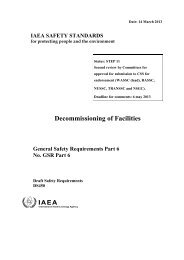
This publication is no longer validPlease see http://www-ns.iaea.org/standards/require the applicant to demonstrate in advance that he is capable of conducting hisproposed mining and milling activities in accordance with the national laws or regulationsrelating to occupational and public safety and health. This could take the formof a safety analysis report. Annexes I and II give examples of licensing processesin France and Canada.2.3. RECORDKEEPINGAn operator of a facility should establish and maintain records giving thedescription of the design of the mine and mill and any significant changes in thedesign, a description of the mining methods used, the design and operation of theventilation system, and the results of all monitoring of the working environment.Ventilation maps and sections should also be maintained. They should show the locationsand capacities of the main fans, the locations of air flow controls and mainmonitoring stations, and the directions and quantities of air flows recorded duringperiodical surveys. The required frequency of these periodical surveys should bedetermined by the competent national authority.The results of monitoring of the working environment should be recorded ina manner that facilitates identification of the locations for sampling within thefacility.These records should be retained and maintained by the operator for the lifetimeof the facility, and upon the termination of operations they should be forwardedto the national competent authority to be retained for the period it deems necessary.Comprehensive records of individual exposures should be retained, preferablyin a national repository established by the national competent authority, for at least30 years after the cessation of work involving exposure to radiation, or for such otherperiod as the competent authority may specify.3. MAIN PHYSICAL PROPERTIES3.1. RADON (222Rn) AND ITS DAUGHTERSRadon decays by alpha emission. Its daughter products, which are of primaryconcern with regard to radiation hazards, have relatively short half-lives. Thesequence of decay of radon and some of its physical properties and daughters aregiven in Table I, and its decay scheme is shown in Fig. 1. Further details are givenin Fig. 2. Table II shows recommended annual limits on intake, annual limits onexposure and derived air concentrations for radon and thoron. Table III showsrecommended annual limits on intake, annual limits on exposure and derived airconcentrations for radon and thoron daughters.4
This publication is no longer validPlease see http://www-ns.iaea.org/standards/222221 ■220 -219 ■218 ■217 -216 ■tcUJ 215 ■CD52 214 ■$ 213 ■5212 •211 ■2102 09 ■208 ■207206 ■I_______ I_______ I________1_________I82 83 84 85 86A T O M IC N U M B E RFIG. 1. Radon decay scheme. (Source: UNITED STATES DEPARTMENT OF LABOR ANDMINE <strong>SAFETY</strong> AND HEALTH ADMINISTRATION MANUAL ON RADIATION MONITORING, US Government Printing Office 603 (1980) 102-112.)Since 210Pb (RaD) has a half-life of 22 years, it is usually considered ascontributing very little to exposure. 214Po (RaC') has a very short half-life and itsalpha particle emission may be treated as mathematically equivalent to an additionalprompt radiation in the decay of 214Bi (RaC). The radioactivity of 214Po (RaC') istherefore taken at all times as being equal to the radioactivity of its parent, 214Bi(RaC).The primary airborne radionuclides are 222Rn and its short-lived daughters218Po (RaA), 214Pb (RaB), 214Bi (RaC) and 214Po (RaC'). Because radon (222Rn) isan inert gas, it is not retained in the respiratory system and contributes little to radiationdose. The short-lived particulate daughters are deposited in the respiratorysystem, however. Consequently, the radiation dose to the respiratory system due tothe alpha decay of inhaled radon daughters is 100 times greater than that due to thedecay of radon itself [5].5
This publication is no longer validPlease see http://www-ns.iaea.org/standards/-8£ a:CO u jSD5oH
This publication is no longer validPlease see http://www-ns.iaea.org/standards/TABLE I. RADON DECAY PRODUCTS AND THEIR PROPERTIESHistoricalnameIsotopicnameHalf-lifePrincipalradiationPrincipalalphaPrincipalgammaenergiesenergies(MeV)(MeV)Radon Rn-222 3.82 d a 5.480 (100%)Radium A Po-218 3.11 min a 6.00 (100%)Radium B Pb-214 26.8 min 0 0.2952 (19%)7 0.3519 (37%)Radium C Bi-214 19.7 min 0 0.6093 (46%)7 1.120 (15%)1.765 (16%)Radium C ' Po-214 164 a: 7.69 (100%)Radium D Pb-210 22 a &Radium E Bi-210 5.0 d 0Radium F Po-210 138 d a 5.30 (100%)Radium G Pb-206 StableRadon is released into the atmosphere in the mine mainly by diffusion andpercolation through ore. Unlike ore dust, which is produced only during miningoperations, emanation of radon is continuous. A frequent source of radon is waterpercolating through the ore body, dissolving radon gas to a considerable extent andreleasing it into the mine atmosphere on entering the mine opening. Drifts in wasteand other barren regions often show unusually high concentrations of radon and itsdaughters owing to this phenomenon.As has already been mentioned, radon daughter products, namely RaA, RaB,RaC and RaC', have relatively short half-lives. This results in a rapid increase intheir concentrations when a source of radon is present and in a rapid decay whenthe daughters are separated from the radon source. Thus, time becomes a matter ofcritical importance in air sampling. Air samples of radon daughters must be analysedsoon after collection before the radioactivity drops to undetectable levels.7
This publication is no longer validPlease see http://www-ns.iaea.org/standards/TABLE II. RECOMMENDED ANNUAL LIMITS OF INTAKE, ANNUALLIMITS OF EXPOSURE AND DERIVED AIR CONCENTRATIONS FORRADON AND THORONType of limitUnitsRn-222Rn-220and DAC(radon)(thoron)ALE B q -h -m -3 3 x 10⁸ 5 x 10⁸ALI Bq 3.6 x 10⁸ 6.0 x 10⁸DACa B q-m ~3 1.5 x 10⁵ 2.5 x 10⁵Note: The primary limits are printed in bold type. For practical application the derived valuescan be rounded to one significant figure [5],One of the critical radiological variables in mine atmospheres is the ratio ofthe respective concentrations of radon and of its short-lived daughters. This ratio,usually expressed as Rn:RaA:RaB:RaC, changes rapidly with the age of the ventilatingair as it flows through the mine and varies significantly with location and time.In relatively fresh (young) air the ratio of the concentration of daughter products tothat of radon is low; it approaches unity in old (stagnant) air. The determination ofthis ratio provides useful information about the source of radon, the effect of ventilationand other modes of control. It allows the conversion of the measured radonconcentration to a radon daughter concentration.This ratio, expressed usually as a disequilibrium factor, is given by:2.7 X 10³ WLF = -----------------------[Rn]where WL is the working level, defined as a unit of the potential alpha energyconcentration (i.e. the sum of the total energy per unit volume of air carried by alphaparticles emitted during the complete decay of each atom and its progeny in a unitvolume of air) resulting from the presence of radon daughters or thoron daughters,equal to the emission of 1.3 x 10⁵ MeV of alpha energy per litre of air. In SI unitsthe WL corresponds to 2.1 X 10⁻⁵ J -m -3 [2]. [Rn] is the radon concentration inBq • L ~ 1. It should be borne in mind that this ratio is influenced not solely by ventilationbut also by plateout (deposition) on mine surfaces. This plateout is usuallydifferent for each daughter. As a result, situations could arise in which disequilibriumlevels of 210Pb several times in excess over its predecessors could beobserved.8
This publication is no longer validPlease see http://www-ns.iaea.org/standards/TABLE III. RECOMMENDED ANNUAL LIMITS OF INTAKE, ANNUALLIMITS OF EXPOSURE AND DERIVED AIR CONCENTRATIONS FORRADON AND THORON DAUGHTERSType of limitand DACUnitsRn-222 (radon)daughters 1Rn-220 (thoron)daughters0A LIPotentiala energyEquilibriumequivalentRn activityJ 0.02 0.06Bq 3.6 x 10⁶ 8.0 x 10sALE Potential J - h -m -3 0.017 0.050a energy WLM 4.8 14EquilibriumequivalentRn activityB q-h-m ~ 3 3.0 x 10⁶ 6.6 x 10⁵DAC Potential J - m -3 8.3 x 10"6 2.5 x 10“5a energy WL 0.40 1.2EquilibriumequivalentRn activityB q-m -3 1500 300Note: The primary limits are printed in bold type. For practical application the derived valuescan be rounded to one significant figure [5], W L = working level; WLM = working levelmonth.abcAssuming a mean breathing rate of 1.2 m 3-h _1 during a working period of 2000 h peryear.218Po (RaA) to 214Po (RaC').212Pb (ThB) to 212Po (ThC')-Radon daughters are heavy metals and some aspects of their interaction withatmospheric dust particles, ions and condensation nuclei are not yet fully understood.RaA, which is formed as a recoiling ion, is usually positively charged owing to thestripping of orbital electrons in the recoiling motion. RaB, which is also initiallyformed as a recoiling ion, should undergo reactions similar to those of RaA. If thedecaying RaA is attached to an aerosol particle, the recoiling RaB atom may eitherpenetrate into the particle or be ejected from the particle, depending upon the directionof recoil. Similar reactions may also result with other radon daughters. Theseatoms originally exist singly in the air but in a short time they attach themselves to9
This publication is no longer validPlease see http://www-ns.iaea.org/standards/atmospheric aerosols and mine walls. Those radon daughters that become attachedto atmospheric aerosols follow the behaviour of these particles or nuclei. Since mostradon daughters become attached to particles around 0.3 ftm in diameter, essentiallyall the radon daughters are respirable.The reasons why most radon daughters become attached to particles of size 0.3ftm are as follows:— The rate of attachment to particles of small diameters (up to about 0.5 /*m) isproportional to the diameter squared (d2), whereas for larger particles it isproportional only to the diameter (d).— The plateout removal rate increases with decreasing particle sizes.— The removal of particles above 1 /im in diameter increases further because ofgravitational settling.A combination of these factors leads to most radon daughters being attachedto particles about 0.3 /xm in diameter.It should be recognized that the standards recommended by the <strong>International</strong>Commission on Radiological Protection (ICRP), as a conservative approach, arebased on an unattached fraction associated with particles with a diffusion coefficientof 0.05 X cm 2-s _1 (d = 1 nm) [5].As the unattached radon daughters are deposited mainly in the upper respiratorytract (Fig. 3), where most lung cancers in miners develop, their importance inthe determination of exposure limits is recognized [5-9]. The exposure limits wouldvary from 12 WLM to 4.8 WLM depending upon the unattached fraction fp of 0%to 5 %. The range reported in literature for the unattached fraction varies between2% and 20%. However, in view of the classification of the unattached radondaughters as having diameters ranging from 0.5 nm to 20 nm, the reportedunattached fraction fp could exceed 20%, since the wire mesh method assumes acut-off at about 1.5-2 nm. The factors that determine the unattached fraction fp arethe following:— Mines in desert areas and mines not using diesel equipment would have lowerconcentrations of condensation nuclei (CN), which would result in highervalues of fp. It should be noted that a visibly dusty atmosphere does not necessarilyhave a high concentration of CN.— It has been observed that the combination of the presence of certain gases, suchas NOx and S 0 2, and high levels of humidity can lead to an increased size ofunattached particles, reducing the probability of attachment or plateout andhence increasing the value of fp [10, 11].It has been assumed by the ICRP that in nasal breathing 50% of the inhaleddecay products are deposited in the lung (trachyobronchial and pulmonary regions).Experimental evidence indicates that the respiratory deposition of radon daughtersmeasured in humans exposed in uranium mines was found to range from 23 % to 45 %10
This publication is no longer validPlease see http://www-ns.iaea.org/standards/=r 0.06> occUJUi Za-j
This publication is no longer validPlease see http://www-ns.iaea.org/standards/FIG. 4. Particle size deposition probabilities fo r particles from nearly molecular dimensionsto those in the visible range. URT: upper respiratory tract. LRT: lower respiratory tract. Notethat the concept o f aerodynamic diameter does not apply to particle diameters o f 10~2 \m.and below.TABLE IV. THORON DECAY PRODUCTS AND THEIR PROPERTIESHistoricalnameIsotopicnameHalf-lifePrincipalradiationPrincipalalphaenergiesPrincipalgammaenergies(MeV)(MeV)Thoron Rn-220 55.6 s a 6.288 (100%)Thorium A Po-216 0.15 s a 6.8 (100%)Thorium B Pb-212 10.6 h P7 0.2386 (45%)Thorium C Bi-212 60.55 min a (36%) 6.051 (25%)6.090 (10%)13 (64%)Thorium C' Po-212 0.3 /is a 8.95 (100%)Thorium C " Tl-208 3.1 min 0 0.5108 (22%)0.5831 (86%)0.8604 (12%)2.615 (100%)Thorium D Pb-208 Stable12
This publication is no longer validPlease see http://www-ns.iaea.org/standards/220219218217216a.wco2155g 214% 213
This publication is no longer validPlease see http://www-ns.iaea.org/standards/FIG. 6. Decay series of thorium-232 (4n)..V. U38wnN ssvw14
This publication is no longer validPlease see http://www-ns.iaea.org/standards/Beta dose rates are less significant than gamma dose rates but have an importantbearing on skin dose in some cases.3.4. SURFACE CONTAMINATIONSurface contamination can be a source of direct external radiation exposure andof internal exposure due to the inhalation of resuspended loose contamination or theingestion of radioactive material. In the mine, surface contamination does notwarrant any separate monitoring programme. This is because the ore is a much moreimportant external radiation source, and the routine monitoring of airborne dust willdetect any significant radioactivity not controlled in the mine dust controlprogramme.In the mill, resuspension of loose radioactive material can pose a problem,mainly in the areas of product precipitation, drying and packaging, where dust islikely to be 60-80% uranium. If very high grade ore is being processed, loose radioactivematerial could cause a problem in other areas. Because uranium has a lowspecific radioactivity, surface contamination at levels high enough to be significantfor health and safety is usually visible as dust.Surface contamination can be fixed or removable. Both types contribute tolocal beta/gamma dose rates, but only removable contamination can becomeresuspended and contribute to air contamination. Removable contamination is thusmore significant, and surface contamination limits are usually set in terms ofremovable contamination.Derived surface contamination limits (DSCL) have been set in order to ensurethat workers and the public are adequately protected from these sources of exposure.For uranium product or ore a DSCL value of 105 B q-m -2 of either alpha or betaactivity is applied by some national competent authorities [14],4. STRATEGIES FOR MONITORING PROGRAMMES4.1. GENERALThe principal objectives o f monitoring in practical radiation protection are:— to ensure that acceptable conditions are maintained in the working environment;— to assess the radiation exposure of individual workers;— to demonstrate compliance with the regulatory requirements of national competentauthorities.15
This publication is no longer validPlease see http://www-ns.iaea.org/standards/The choice of a particular monitoring programme is dictated by the end useof the results. Two types of programme exist: a survey programme to provide datafor engineering control purposes, and a direct assessment of workers’ exposures,done as accurately as possible for purposes of ensuring compliance and maintainingexposure records. In practice, monitoring programmes tend to combine these twopurposes.At the design stage, rough estimates can be made of potential radiationexposure in both the mine and the mill. However, field monitoring should commenceas soon as mine development starts. In the mill, the monitoring programme shouldstart when ore is introduced into the process. The initial screening must cover everyworkplace and travel-way. The studies should be designed to yield information onthe spatial and temporal variations in the various parameters that contribute toworker exposure. If the results of the screening studies differ from the originalestimates, engineering modifications should be made to improve the working conditions.Experience from the screening surveys is used to define the routine monitoringprogramme for each workplace.Monitoring for engineering control usually employs area measurements; thatis, measurements at specified physical locations. These may be either grab samples(collected over a short period of time) or continuous samples (collected over longertime periods such as a full shift). W orkers’ exposures may be assessed by means ofarea monitoring or from the personal dosimeters worn. The level of effort requiredfor the assessment of individual exposures varies with the specific conditions. Inmost countries, area monitoring is used to determine individual exposures to radondaughters.The use of personal dosimeters (see Section 6) has the obvious advantage ofeliminating errors in occupancy times from the calculation of individual exposure ordose. However, this advantage must be weighed against the factors of the cost, reliabilityand convenience (to wearers) of personal dosimeters. If the cost of the deviceis high and exposures are low, its use is difficult to justify. If the device is notreliable, good area monitoring may give better data than poor personal dosimetry.Finally, the convenience to the wearer is most important. The full co-operation ofthe worker is necessary to ensure that the dosimeter is being properly worn and used.The use of devices that are large or heavy or unduly complicated in their functionshould be avoided.Where personal dosimetry is judged to be either unnecessary, not technicallyfeasible or not cost-effective, a continuing programme of area monitoring should bedesigned that can be combined with workers’ exposure times to calculate the desiredindividual exposures and doses. The monitoring programme should be designed toyield data on these exposures to the desired degree of accuracy with the minimuminvestment of resources. Some competent authorities use a criterion of ±50%accuracy at a 95% confidence level for estimating individual exposures.16
This publication is no longer validPlease see http://www-ns.iaea.org/standards/If the parameter being measured is essentially constant and has a low value incomparison with appropriate limits, and if there is no reason to expect short termexcursions, then less frequent measurements would be acceptable. For example, forsome operations annual measurement of gamma dose rates might be acceptable. Iflarge variations occur in the relevant parameter, exposures can be assessed bycontinuous measurement, grab sampling using some statistical technique to determinethe required number of grab samples (randomized grab sampling), or personalmonitoring. From the results of these samples the mean value can be calculated andused to estimate the workers’ exposures.Where exposures are relatively high, such as greater than 50% of the annuallimit, the monitoring programme must be designed to give the most reliable assessmentpossible of the exposure. Where exposures are relatively low (less than 10%of the limit, say) it will usually be acceptable to reduce the monitoring effort bymaking simplifying assumptions, provided that such assumptions are not likely toresult in a significant underestimate of the real exposure. For example, radondaughter concentrations could be measured at the point in a work area where theyare known to be at a maximum in order to assess the exposures of all workers inthat area.When all individual exposures and doses are controlled within the relevantlimits, the collective dose should also be calculated. This can then be used in theoptimization of the radiation protection programme [3].4.2. EXTERNAL RADIATIONAlthough nuclides of the uranium and thorium chain emit both beta and gammaradiation, only the gamma radiation is of significance in considering the risk ofexternal exposure in mining [15], The gamma radiation field will depend upon thegrade of ore and can be expected to be higher wherever ore or concentrate is stockpiled.In the mining of low grade ore, the dose rates are low enough that it maysuffice to make periodic radiation surveys and estimate workers’ doses fromoccupancy factors; however, inexpensive personal external dosimetry services areavailable in many countries, and it is recommended that these be used. A quarterlydosimeter change is generally sufficient, except for film dosimeters, which mayrequire more frequent changes. In the rough mining environment, thermoluminescentdosimeters (TLDs) are preferable to photographic film dosimeters owing totheir ruggedness. High radiation fields are quite likely in mines and mills with highgrade ores (containing more than a few per cent U30 8). A monthly or quarterlychange period for TLDs, which is normally sufficient for record keeping purposes,will not be adequate for dose control purposes. High radiation fields should be identifiedand their levels should be measured with suitable radiation survey instruments.The exposures of workers in these areas may be controlled by limiting occupancy17
This publication is no longer validPlease see http://www-ns.iaea.org/standards/times or by installing shielding. Direct reading dosimeters can be used in high radiationfields.Methods are available for calculating workers’ gamma radiation dose rates,given the ore grade and the exposure geometry [16]. These should be employed inthe design phase of the mine and mill. Radiation surveys should be made as new orezones are developed in mines for high grade ore, in order to allow appropriate planningof mining operations to maintain gamma doses as low as reasonably achievable.Radiation surveys should be made in mills soon after ore is introduced. Lowvalues in initial results should not be taken as an indication of absence of risk.Particular radioisotopes may build up in some parts of the mill circuit and cause highlocalized radiation fields. Surveys should therefore be repeated frequently until someoperating experience is gained. When changes are made in the operation of the mill,the surveys should be repeated.4.3. RADON (222Rn) AND RADON DAUGHTERSRadon daughters are of primary concern in the monitoring programme, butradon measurements are also made occasionally for such special purposes as determiningequilibrium factors, determining the age of the air and measuring environmentalreleases. Because of the large number of workplaces in a mine-mill operationand the variability in radon daughter concentrations, it is not realistic to rely onmeasurements in a few locations being representative of the entire operation; nor isit usually feasible to monitor workplaces continuously.Traditionally the mining industry has responded to these problems by meansof a grab sampling programme, whereby each location is sampled periodically witha frequency dependent upon past results. Where high concentrations are measured,a higher frequency of sampling is usually used. These sampling programmesgenerally result in approximately weekly samples in workplaces and monthlysamples in travel-ways, lunch rooms and other places. One problem with this typeof sampling is that the person doing the sampling usually sets up a schedule on thebasis of the most efficient use of his time rather than a truly representative samplingplan. For example, a particular location may be sampled at the same time on thesame day each week, and changes in air quality arising from changes in miningoperations through the day or from day to day may be completely missed. This canlead to incorrect decisions regarding ventilation and erroneous estimates ofindividual workers’ exposures. These difficulties can be avoided by developing asampling plan based on sound statistical methods (see Section 5.2.1.1). However,this requires that the distribution of concentrations is truly random, which is not thecase during occurrences such as a breakdown in ventilation.The required sampling frequency is directly related to the coefficient of variationof the results. In areas where radon daughter concentrations are low, the relative18
This publication is no longer validPlease see http://www-ns.iaea.org/standards/errors in measurement may be quite large. A statistically determined randomsampling programme, if used, can give rise to a requirement for a large number ofsamples to give the desired accuracy in the exposure estimates. It is obviously lessimportant to measure exposure with great precision when the absolute value is muchless than the limit; a judgement is therefore necessary. The radiation protectionofficer must decide how best to employ the resources, concentrating greater effortsin areas where exposures are higher.In addition to establishing a sampling frequency, it is necessary to considerwhere samples are to be taken within the workplace. This is particularly importantin large underground openings where airflow patterns can be quite complex andworkers are not restricted to a specific location. Ideally, samples should be taken inthe worker’s breathing zone, which for these purposes could be defined as betweenwaist and head height and close to the worker’s location. It is important for theperson taking the sample to understand the airflow patterns. To some extent theperson’s own and the workers’ senses may be relied upon. However, using a smoketube to check the airflow, particularly for recirculation and stratification of air flows,is recommended.In some mines the exhaust air from the workplace is sampled and the resultsare assumed to indicate the general conditions. In most instances this is likely to giveconservative results, but it is possible that, owing to short-circuiting of the airflow,a worker could be in an eddy or dead end and be exposed to unknown radon daughterconcentrations. At some mines, area samples in large stopes are taken by a personwalking around the stope during the five minute sampling interval to cover all areaswhere workers are normally stationed during the shift. This gives an average samplefor that workplace. In drifts and travel-ways this averaging sampling technique canbe particularly useful, because workers are not normally working in these areas, ando f concern is the average condition over the length of the travel-way rather than thatin one particular spot.In sampling for control purposes, measurements of radon concentrations areuseful. From the combination of concentrations of radon and radon daughters, theequilibrium factor can be calculated. By means o f the tunnel formula [17] the ageof the air can be estimated. ‘Old air’ may indicate that air has been recirculatedwithin the workplace or that the contaminated air has travelled some distance throughthe mine workings, whereas young air with a high radon concentration indicates anearby source of contamination.The radon concentration is also useful to indicate for how long the air willcontinue to be of satisfactory quality. Young air with a high radon concentrationwould be unsuitable for ventilating another workplace a long distance away becauseradon daughter concentrations will increase by the time the air reaches the distantworkplace. When the quality of air in a particular workplace is unsatisfactory, thefirst action should be to check the quality of the immediate intake air. When this airis of unsatisfactory quality it will be necessary to take more samples further upstream19
This publication is no longer validPlease see http://www-ns.iaea.org/standards/to identify the source(s) of the contamination. Samples should be collected atbranches in the air distribution system and at any places where mined out areasmay connect to the primary airway. Leaking bulkheads can be a major source ofcontamination.4.4. THORON (220Rn) AND THORON DAUGHTERSSampling strategies for thoron and thoron daughters are essentially the sameas those for radon and radon daughters, but the widely different half-lives of theradionuclides necessitate changes in the techniques employed. The very short halflifeof thoron means that measurements with ionization chambers or scintillation cellsmust be performed immediately after sample collection. However, in most cases thepresence of thoron is inferred from measurements of daughter concentrations mademany hours after sample collection. The accurate determination of the thorondaughter concentrations requires a counting delay until the short-lived radon daughtershave decayed to negligible levels (generally three hours). Details are given inSection 5. Several of the detection methods used for radon daughters can be modifiedby changing the delay times and counting times to give acceptable measurements ofthoron daughters. These modifications will affect the work cycle of the person takingthe sample, possibly changing the number of samples that can be processed in a shiftand changing the person’s optimized sampling route through the mine. However, thebasic theory, relating sampling frequency to the coefficient of variation of the results,remains unchanged.Because of their different half-lives, thoron and its daughters respond differentlyto ventilation changes. The very short half-life of thoron means that appreciableventilation changes have virtually no effect on its concentration. However, thorondaughter concentrations are significantly more affected than radon daughter concentrations.These characteristics should be kept in mind when sampling results are usedto trace the sources of high concentrations and to assess the effects of ventilationchanges.The presence of thoron daughters will influence the results of radon daughtermeasurements, resulting in overestimates of radon daughter concentrations. Whenthorium is present at appreciable levels, the presence of thoron and its daughtersshould be checked for to assess the magnitude of the resulting error.Personal dosimeters commercially available for monitoring exposure to radondaughters can also measure exposure to thoron daughters. The use of these devicesis subject to the same limitations as is their use for radon and radon daughters.Except in the case of a thorium mine or mill, thoron daughter exposure is generallymuch lower than radon daughter exposure and is unlikely to require individualpersonal dosimetry.20
This publication is no longer validPlease see http://www-ns.iaea.org/standards/4.5. LONG-LIVED ALPHA EMITTERSAt the grades of commonly mined ores (less than 1% U30 8), long-lived alphaemitters in ore dust are usually not a significant source of exposure. At ore gradesof up to about 3% U3Og [18], the limitation due to airborne silica will usually placea stricter constraint upon dust concentrations than does radioactivity. However, atore grades in excess of 3% U3Og, and when the ore is not high in silica, this sourceof exposure could become important. Screening surveys should be conducted soonafter ore is encountered. Gross alpha counting after decay of the radon and thorondaughters may be used to assess the initial samples, but this is only accurate if theore is in radioactive equilibrium. Should the ore not be in equilibrium, estimatesbased on gross alpha counting can have large errors. Thus, if the indicated ore dustconcentration exceeds about 25 % of the DAC, the radioactive equilibrium of the oreshould be checked by analysing the sample by radiochemical methods followed bya suitable alpha counting technique. Gross alpha counting is also subject to errorsowing to self-absorption in extremely dust laden filters.A basic sampling frequency of once every three months is recommended, buthigher frequencies should be employed in the product packing area of the mill or inareas where values are high or results are highly variable. Although size selectivesampling need not be employed for initial screening, if high results are obtained, itshould be used to make intake estimates and for decisions on the routine programme.In the precipitation, drying and packing areas of the mill, inhalation of uraniumdust can be a significant risk. A routine air sampling programme is important in theseareas. The DAC will depend upon the chemical form of the uranium [1, 5], If thedrying process employs high temperatures (greater than 300°C), Class Y materialcan be expected.Some of the personal alpha dosimeters available include a filter which can berecovered for estimation of the exposure due to long lived radionuclides. Exact determinationcan only be made if appropriate radiochemical methods are applied.Simpler personal air samplers of the type used elsewhere in the nuclear industry canalso be used to collect the sample. As noted in Section 4.1, the decision to usepersonal samplers must weigh the extra cost and inconvenience against the greaterprecision offered in comparison with area sampling.4.6. SURFACE CONTAMINATIONA reasonably good housekeeping programme will ensure that there is generallylittle need for extensive surface contamination monitoring. Only an occasionalsurvey is advised, perhaps quarterly until some operating experience is gained.However, if serious problems due to dust are encountered in a particular area, asurvey for loose contamination should be made to ensure that continuing problems21
This publication is no longer validPlease see http://www-ns.iaea.org/standards/are not caused by resuspension. Similarly, a survey for loose contamination may helpto identify the source of any unexplained airborne radioactivity.When it is necessary to enter a processing vessel, surface contamination levelsshould be checked. It may be necessary in these circumstances to make use ofpersonal protective equipment, such as respirators and disposable coveralls.Contamination control is important for personnel and equipment leaving theoperating area or the site. Any reasonable industrial hygiene programme thatincludes a change of clothes and a shower will generally suffice, but occasional spotchecks with a survey meter or the use of an employee operated exit monitor will giveadded assurance. Equipment and materials leaving the facilities for the public domainshould be surveyed to ensure that limits for surface contamination determined by thecompetent authority are not exceeded.Certain areas of the facility, such as offices, lunch rooms, bunkhouses, firstaid rooms and laboratories, should be checked in occasional surveys. Laboratorysurveys may be important more to reduce the risk of contaminating low radioactivitysamples than for any considerations bearing on the health and safety of personnel.5. MONITORING METHODS5.1. RADON (222Rn) AND THORON (220Rn)5.1.1. Radon measurement with scintillation cellsPrincipleThe alpha scintillation cell, otherwise known as the Lucas cell [19, 20], iswidely accepted for measuring radon in both mines and mills because the techniqueis convenient and reliable and has been in existence almost from the beginning ofindustrial scale uranium ore recovery. It consists of a 100-200 mL vial coated onthe inside with silver activated zinc sulphide phosphor, which emits flashes of lightwhen struck by alpha particles. To perform a measurement, an air sample of radonis drawn into the chamber and sealed. The scintillations emitted by the phosphor arethen measured by placing the transparent surface of the cell in contact with aphotocathode detector in a light-tight enclosure. Usually, this count is delayed forthree hours after sample collection for equilibrium to be reached between radon andits daughters, but it may be made more promptly if desired. With reasonable care,a sensitivity of 0.2-0.4 B q L -1 is attainable with short counting periods. The practicallimit of sensitivity attainable with special care and a long counting period (morethan 100 min) is of the order of m B q-L -1.22
This publication is no longer validPlease see http://www-ns.iaea.org/standards/EquipmentThe basic equipment consists of the scintillation cell and the photomultipliercounter. A small manual or battery powered air pump with chambers designed forflow-through sample collection may also be used; a vacuum pump is required for cellevacuation.The scintillation cell may be constructed of glass, glass and metal or plastic.The side that makes contact with the photocathode counter must be flat and madeof a transparent material. It may be either uncoated or coated with phosphor on theinside, but the other inner surfaces must be coated. The vertical dimensions of thechamber do not usually exceed the range of alpha particles in air. This optimizes thecounting efficiency but limits the volume and hence the sensitivity. In the classicdesign described by Lucas [19], the side opposite the light transmitting surface ishemispherical, but other shapes, including cylinders [2 1, 22] and truncated cones,are satisfactory for routine monitoring. Cohen et al. [23] investigated the dependenceof sensitivity on cell size and concluded that the use of cells of up to several litresin volume is still feasible if the optical properties (the transparency of ZnS paste andthe reflectivity of the underlying walls) are optimized. A cell of diameter 10 cm canbe extended to at least 50 cm in length without any difficulties being caused by aninsufficient pulse height.The cell may be equipped with one or two valves for sample collection. Witha single valve, the air sample is drawn into a previously evacuated sealed chambersimply by opening the valve. If there are two valves, sample air is drawn throughthe chamber with a small pump, replacing the air in the chamber with air from theenvironment. In both modes of sampling, the valves are sealed before and aftersample collection, and it is customary to connect a high efficiency filter to the inletvalve to prevent the entry of long lived alpha contamination during aspiration.Experience from the international intercalibration study of the Nuclear <strong>Energy</strong><strong>Agency</strong> of the Organisation for Economic Co-operation and Development(OECD/NEA) [24] shows that most commercially available cells, if transported byair after filling, develop leaks in the valves and in the epoxy joints around thewindows resulting from air pressure differences. This effect was rather pronouncedafter intercontinental shipment. Such leakage would result in serious errors ofmeasurement. Checks for leaks should be made by filling a cell with radon andfollowing its decay to determine whether the proper half-life is maintained (leaksresult in shorter measured half-lives), both at overpressures and at underpressures(± 20%).An alternative method of checking for leaks is to place the Lucas cell underpressure, both positive and negative. The manometer reading should be recorded andchecked from time to time for any unacceptable leakage. A reading that rises towardsatmospheric pressure indicates a leak in the cell. Caution should be exercised duringthe test.23
This publication is no longer validPlease see http://www-ns.iaea.org/standards/The photocathode counter is the usual device for alpha scintillation counting.For convenience, the surface of the photomultiplier tube must face upwards incontact with the scintillation cell, and the light-tight enclosure must be large enoughto accommodate the cell. For most routine monitoring, cells may be counted in thelaboratory and line powered equipment is satisfactory. In cases where promptmeasurements are required, as in diagnostic sampling, portable battery poweredcounters are desirable. Battery powered counters with a photomultiplier of diameter10 cm and weighing less than 5 kg have been developed for use in uranium mines.ProcedureFor efficient application of this method, many already evacuated scintillationcells are carried in a suitable case into the mine or mill, used for sample collection,and then returned to the counting facility for analysis. The time as well as the locationof each sample are noted for later correction for radon decay.As an alternative to sampling directly with scintillation cells, an additionalconvenience may be gained in the field by using ordinary small containers (previouslyevacuated) such as liquid propane gas cartridges or polyamide foil containers[25]. Thus, a reduction of both weight and volume may be achieved, enabling manysample containers to be carried at once. This is also advantageous if samples are tobe sent to a laboratory by surface mail. However, there is an accompanying loss insensitivity in proportion to the diminution in the volume, and this method alsorequires the extra analytical step of transferring the sample to a scintillation cell inthe laboratory.After the collection of radon samples in the scintillation cell, radon decayproducts build up until transient equilibrium with the radon is reached. If the sampleair is filtered in the process of collection, equilibrium is reached after several hours.For unfiltered sample air, equilibrium is reached in a shorter but unpredictable time,depending on the concentration of radon decay products at the sampling location. Atequilibrium, alpha activity due to radon and its decay products is three times as highas that due to radon alone. Consequently, a counting delay of three hours to establishtransient equilibrium has the dual advantage of maximizing the sensitivity andeliminating a time dependent correction for the buildup of radon daughters. If promptmeasurement is desired, however, this correction may be applied by using appropriategrowth curves.Further delay beyond three hours, up to 24 hours or more, reduces the sensitivityonly marginally since radon decays by only 18% per day. The cells may thereforebe counted at almost any convenient time within a few days of sample collection.However, the optimal delay is about three hours. It is a good practice to checkoccasionally whether the radioactive material in the cell decays with the decayconstant of radon. Any greater decay constant would indicate leakage, as mentioned24
This publication is no longer validPlease see http://www-ns.iaea.org/standards/earlier, while a smaller constant would indicate the contamination of the cell withradioactive material of a longer half-life.With a ten minute counting period, a radon concentration of 0.4 B q -L -1 canbe measured with a counting error of about ±15% . Thus ten minute counts aregenerally adequate for routine measurements. Higher precision and/or measurementof lower concentrations are attained with longer counting periods.The radon concentration is calculated by means of the following equation:where:Crj, —Cri,RXTEVKRKeXT2.2 EVis the radon concentration in Bq • L - 1,is the number of counts per minute for the scintillation cell,is the radon decay constant in m in_ I,is the time from sample collection to sample counting in minutes,is the fractional cell counting efficiency with radon and radon daughtersat equilibrium,is the cell volume in litres,is the correction for the buildup of radon daughters if the samplingtime T is less than three hours.The factor E is determined empirically using standard radon sources. Thefactor K is used for samples requiring early counting after collection to take accountof the changing response due to the increase in the concentrations of radon daughterswith time. It is reproducible only if the sample air is filtered to ensure that it containsno radon daughters at time zero. K is determined experimentally by periodicallynoting the cell count rate after filling with radon to a known concentration, or it maybe calculated by means of the equation derived by Jonassen and Clements [26],LimitationsAlthough reliability is among the major attributes of the scintillation cell,certain points have to be considered to avoid errors.(a)(b)The standard deviation of Lucas cell counts is not simply determined by thecounting statistics, probably owing to the fact that ‘the same’ nuclei can becounted more than once (first as radon, then as RaA and RaC') [27, 28]. Ithas been shown that in such cases the standard deviation of the count isa = (JR)1/2, where the factor J ranges from 1.2 to 2.9. Longer countingperiods can compensate for the poorer statistics.Additional uncertainty is caused by non-uniform plateout of radon daughterson surfaces inside the cell, including surfaces covered with ZnS. The nonuniformityresults from the presence of charges on surfaces; therefore it is not25
This publication is no longer validPlease see http://www-ns.iaea.org/standards/(c)(d)(e)(f)(g)advisable to use plastic cells, especially in dry climates (note: high humiditytends to discharge such spots of charge). The magnitude of this error can beas high as 20% [29]. Non-uniformity is also caused by changes in convectionpatterns inside the cell, resulting from temperature differences between theinside and the outside [30]. It is difficult to determine exact values for theseerrors; however, it is common to find the standard deviation of a Lucas cellcount to be several times greater than the square root o f the count. The magnitudeof this error can be determined by repeated counting of a cell filled witha known amount of radon for extended periods under known measuringconditions.The cells should be purged of sample air promptly after counting, to curtailthe continuing buildup of long lived radon daughters. In single valve cells thisis done by applying a vacuum; in dual valve cells, by drawing through theequivalent of several cell volumes of radon free air or N2. Despite routinepurging, cell background radiation may gradually increase with use of the celland should be checked periodically. It can normally be subtracted from thecount obtained for subsequent samples; if it becomes excessive, it can bereduced by removing the zinc sulphide phosphor from the cell walls andrecoating them. Routine delay of counting by more than about three hourstends to cause higher background counts from the increase in the concentrationof and the deposition of 210Po.Traces of gaseous impurities are reported to alter the cell response slightly[30], but this effect does not constitute a significant problem in practice,certainly not for small cells.The photomultiplier counter system should be periodically standardized (bychecking the operating voltage).It is advisable to have a cell containing a known amount of radium to checkthe reproducibility of the photomultiplier and counting system.A pressure correction should be made for each cell. For example, for a cellof volume 100 cm 3 at an elevation of 1600 m above sea level, the efficiencyincreases by 6%.5.1.2. Thoron measurement with scintillation cellsThoron can be measured with scintillation cells by adapting procedures similarto those for radon, with some exceptions:(a)(b)It is not practicable to wait for daughter products to reach equilibrium levels.Appropriate growth curves corresponding to the time interval betweensampling and counting should therefore be used.If radon is present in sufficient concentration, one cell collecting only radon(using a suitable membrane) and another collecting radon and thoron could beused to make appropriate corrections.26
This publication is no longer validPlease see http://www-ns.iaea.org/standards/5.1.3. Radon measurement with ionization chambersThis procedure uses a pulse ionization chamber of volume about 3 L filled withradon gas in an oxygen free atmosphere (N2, H2). The exact procedures aredescribed by Fisenne and Keller [31]. Pulse ionization chambers serve as a primarystandard when radium solutions certified by the US National Bureau of Standards(NBS) are used. An alternative use of an ionization chamber is with an ultrasensitiveelectrometer. The inlet air passes through a filter and a drying agent in either continuousor discontinuous mode. However, these procedures have not been checkedfor radon loss in the drying agent in the discontinuous mode of operation.5.1.4. The two filter method for radonPrincipleThe two filter method is sometimes used for environmental measurementswhen the errors inherent in this method are small compared with those in countingstatistics. In this method, all radon daughters are removed from the sampled air bymeans of the first of the two filters in the instrument, and the radon concentrationis then deduced from the count on the second filter [32].Air is drawn through a metal tube fitted with a high efficiency filter at eachend (see Fig. 2 o f Ref. [32]). The inlet filter removes all radon daughters, admittingonly radon together with air into the tube. The radon partially decays in transit, producingRaA atoms, most of which are collected on the exit filter, the remainder beingdeposited on the tube wall. After a short sampling period, the exit filter is removedand promptly analysed in an alpha counter. The amount of radon is calculated bymeans of an equation that accounts for the tube’s dimensions, the flow rate of thesample, sampling and counting intervals, and the fraction of RaA that reaches theexit filter.The sensitivity of the method depends on the tube size, the sampling rate andthe sampling and counting intervals. With a tube 50 cm long and 50 mm in diameter,and with sampling and counting intervals of five minutes, the sensitivity is0.2-0.4 Bq L -1. A sensitivity of about 5 m B q-L -1 can be attained with a largertube and longer intervals.The inlet filter may be used to measure the concentration of radon daughters,as described in Section 5.2, if desired.This method can also be used for measuring the concentration of radon inbreath [33],EquipmentThe basic equipment consists of a tube equipped with two filter holders, filterpaper, air pump, flow meter and alpha counter.27
This publication is no longer validPlease see http://www-ns.iaea.org/standards/The tube is preferably a metallic cylinder with a high efficiency glass fibrefilter in a holder at each end and a connection from the exit filter to an air pump.A convenient tube size is 50 cm long with a diameter of 50 mm. The diameter ofthe filters should be the same as that of the tube. The exit filter holder in particularshould be of a type that disassembles easily so that the filter may be removed andcounted promptly after sampling.The pump should have a capacity of 5-10 L -m in -1 against the resistance ofthe two filters of diameter 50 mm in series, and should be equipped with a flow meterof suitable range and a vacuum gauge to indicate the pressure drop across the firstfilter. For use in mines, it should be battery powered.The alpha scintillation counter-scaler may be of conventional design; for usein mines it should be battery powered and capable of operation in adverse environmentalconditions. If the alpha counters available accept only filters of smallerdiameter than that specified (50 mm), an exit filter smaller in diameter than thetwo filter tube can be used without introducing any significant error into themeasurement.ProcedureA five minute sample is collected through the two filter tube at a flow rate of5 or 10 L • min ~~1. Promptly after sampling, the exit filter is removed and placed inan alpha counter. A five minute count is begun one minute after the termination ofthe sampling. The radon concentration is calculated from the following equation:'- R n12JXpEZVwhere:Cr„XEZVFis the radon concentration in B q -L ~ ';is the number of alpha counts;is the counting efficiency;is a factor that is a function of the sampling and counting times:Z = 1.672 for a 5 min sample and a 5 min count (see Tables Vand VI);is the tube volume in litres;is the fraction of RaA atoms formed in the tube that deposits on theexit filter (see Table VII).Longer sampling and/or counting periods may be used to improve the sensitivityof the method. Appropriate values of Z may be found in Tables V and VI.The inlet filter may be used for measuring the radon daughter concentrationsif desired. Otherwise, it need be replaced only occasionally when the dust loadingbecomes excessive.2 8
This publication is no longer validPlease see http://www-ns.iaea.org/standards/TABLE V. VALUES OF Z FOR USE IN THE TWO FILTER METHOD FORMEASURING RADONt T, t 2 Z5 1 6 1.6725 1 15 2.5975 1 30 3.4115 1 100 6.31410 1 6 2.31210 1 15 3.80310 1 30 5.42510 1 100 11.06815 1 6 2.65615 1 15 4.63415 1 30 7.07015 1 100 15.281Note: Z is the decay correction factor (min);t is the sampling time (min);T, is the start of the counting period (min);T2 is the end of the counting period (min) (T = 0 at the end of the sampling period).LimitationsFor the tube size discussed earlier, the sensitivities achievable by this methodare not better than those achieved with scintillation cells. The reproducibility of thismethod is rather poor (results could differ from day to day by as much as 25%,although the precision is very high), probably because the flow and plateout characteristicschange. For example, if the pressure drop across the first filter changes bya factor of two (as a result of using a different filter, for instance), the count changesby 25% [11]. The presence of trace gases (N 02) and humidity affect the diffusioncoefficient, resulting in counts that differ even more [34],Leaks on the first filter, indicated by an insufficient pressure drop across thefilter, can cause significant errors by allowing outside radon daughters to deposit onthe exit filter. The exit filter is vulnerable to contamination by contact with almostany surface or even with mine air. Membrane filters are especially prone to contaminationwith mine air because of inherent electrostatic forces, and they should thereforenot be used. To prevent contamination, filters should be sealed until used and29
This publication is no longer validPlease see http://www-ns.iaea.org/standards/TABLE VI. VALUES OF Z FOR USE IN THE TWO FILTER METHOD FORMEASURING THORONt T, t 2 z10 1 11 0.0126210 60 70 0.0572410 10 110 0.5159110 10 1010 6.3142030 1 11 0.0671330 60 70 0.1849830 10 110 1.6998930 10 1010 18.98648120 1 11 0.60925120 60 70 0.88502120 10 110 8.48933120 10 1010 75.32111Note: Z is the decay correction factor (min);t is the sampling time (min);T, is the start of the counting period (min);T2 is the end of the counting period (min) (T = 0 at the end of the sampling period).then manipulated with forceps. If glass fibre filters are used, correction must bemade for self-absorption.The two filter method usually has relatively low count rates, partly because ofa high degree of plateout of the freshly formed and hence mostly unattached RaA.It has been suggested to correct for this effect by adding aerosols to the air stream.Because of the low count rates, the background radiation of the alpha counterbecomes significant. This should be checked periodically, especially in mining applications,as the counters may gradually accumulate contamination by radon daughtersthrough plateout.5.1.5. The two filter method for thoronPrincipleThe two filter method for thoron is identical to the two filter method for radonexcept for the following:30
This publication is no longer validPlease see http://www-ns.iaea.org/standards/TABLE VII. VALUES OF Ff FOR USE IN THE TWO FILTER METHOD FORMEASURING RADON AND THORONFf A* Ff0.005 0.877 0.25 0.4200.008 0.849 0.30 0.3840.01 0.834 0.35 0.3490.02 0.778 0.40 0.3240.03 0.737 0.45 0.3020.04 0.705 0.50 0.2820.05 0.678 0.60 0.2480.06 0.654 0.70 0.2200.07 0.633 0.80 0.1970.08 0.614 0.90 0.1780.09 0.596 1.00 0.1620.10 0.580 1.50 0.1100.12 0.551 2.00 0.0830.14 0.525 2.50 0.0670.16 0.502 3.00 0.0560.18 0.481 4.00 0.0420.20 0.462 5.00 0.033Note:where:/j. = 7rDL/q = 3.1416 DL/qD is the diffusion constant: 0.085 cm2-s_l for RaA, 0.06 cm2-s'1for ThA.L is the tube length (cm),q is the flow rate (cm3-s_1).Ff is the fraction of atoms formed in the tube that arrives at the exit filter.(1) Values of Z are different (see Table VI);(2) The sensitivity is two to three times lower for the same tube size.This method can also be used for measuring thoron in breath [33], Reference[33] also describes the use of an aerosol as a technique to reduce plateout toless than 5%.ProcedureThe sampling procedure is the same as for radon. Tubes larger than thosedescribed earlier can be used to improve the sensitivity, but the flow rates must also31
This publication is no longer validPlease see http://www-ns.iaea.org/standards/be increased to maintain the transit time through the tube at six seconds or less. Thisis necessary owing to the short half-life of thoron gas.5.1.6. Radon measurement with nuclear track detectorsPrincipleWhen alpha particles from radon (or its daughter products) impinge on certaintypes of plastic they cause radiation damage tracks in the material. The tracks canbe made detectable by chemical or electrochemical etching. A piece of such plasticcan be used as a detector if placed in a cup with radon containing air for a givenperiod. The number of tracks on the material is equal to the number of alpha particlesthat have reached the plastic, and can thus be related to the average concentrationof radon. Since this technique does not require pumps or electronic equipment, it isthe least expensive way to measure average radon concentrations.EquipmentAlthough continuous monitoring (see Section 5.1.8) gives the most accurateinformation on radon concentrations at a given location, it is usually sufficient todetermine the time averaged concentration over a period. Many instruments havebeen developed for such time integrated measurements [21, 35-39]. Most of theseinstruments use nuclear track detectors of polycarbonate or cellulose nitrate.In the nuclear track detection method [40, 41] the detector is placed in a smallcup to which air has access through a diffusion barrier. The barrier serves thepurpose of filtering out radon daughters and preventing the entry of other particulatematter. Furthermore, a special membrane may be used to slow the rate of gaseousdiffusion and thus eliminate substantially the response to thoron [42]. After exposurethe tracks are made visible by chemical or electrochemical etching. In a possiblyuseful approach taken by Urban and Schmitz [42], a small electrically conductive cupis attached to a hard hat (helmet).ProcedureCommercially available cups are unsealed and placed in a specific area for arecorded period of time. The cups are then resealed and sent to the manufacturer forcounting to obtain the time integrated count.LimitationsThe nuclear track technique is very inexpensive; however, the standard deviationis usually several times larger than that calculated from the counting statistics.32
This publication is no longer validPlease see http://www-ns.iaea.org/standards/This may be due to electrostatic charges, which are usually present on any plasticsurface that is not conductive, but no data are available yet. (Figure 7 shows theinhomogeneous distribution of the track density.) It is also necessary to apply analtitude correction, since even for small volumes the number of tracks is a functionof the ambient pressure.5.1.7. Radon measurement with thermoluminescent detectorsPrincipleWhen an alpha particle impinges on crystals of certain ceramic materials, asmall amount of its energy is stored in a form that is released as light upon heating(thermoluminescence). The amount of energy released as light is proportional to thetotal energy of the alpha particle.EquipmentAs with the nuclear track detection technique, this method is best for timeintegrated measurements. In one version of the thermoluminescent dosimetry (TLD)system, the disc is placed a short distance from the surface of the second filter ina two filter device [17]. Air is drawn continuously through the system at a rate of3 L -m in -1 with a line or battery powered pump. The limit of detection is as lowas 2 B q-m -3 for an exposure of one week. In another version the radon diffusesinto the detector enclosure through a porous barrier that filters out radon daughters[35]. Newly formed and positively charged RaA atoms are deposited in an electricfield onto a foil backed with a TLD chip. Beds of silica gel are used to reduce themoisture content of the air in the detector enclosure, since the collection efficiencyof the system declines with increasing humidity.Another method combines the capacity of activated charcoal to collect radonand the capacity of TLD chips to detect it [43]. All the aforementioned methods usesome design feature concentrating radon on or close to the TLD chips, since thechips are usually small (to reduce the influence of the gamma background and toallow light to be emitted during heating), and because their sensitivity is less thanthat of the nuclear track detection method. As for the nuclear track detection method,the readout is usually done commercially.ProcedureIn the same way as for the nuclear track method, the instruments are activatedat the sampling location and exposed for a recorded period of time.33
This publication is no longer validPlease see http://www-ns.iaea.org/standards/FIG. 7. Illustration of the inhomogeneous distribution of track density.34
This publication is no longer validPlease see http://www-ns.iaea.org/standards/LimitationsClogging filters, unevenness of flow through the filters (unless the pump isself-regulating) and pump failures are common problems of active pump systemswith filters. Since some TLD chips fade, it is advisable to calibrate the systemperiodically against known concentrations.The collection of the radon daughters (RaA) by electrostatic field depends onthe state of the RaA charge. At higher humidities and in the presence of trace gases,the state of the charge is uncertain and the reproducibility is rather poor. Furthermore,the charcoal device is sensitive to temperature and, to a lesser extent,humidity. The errors of all these methods can be considerable primarily because ofthe problems with the collection techniques.The same remarks apply to charcoal canister methods [44-46] that measure thegamma radiation from absorbed radon by means of Nal(Tl) (thermoluminescent)crystals. Radon absorption is temperature sensitive (approximately ±30% for20 ± 5°C temperature variation); in addition the method assumes a constant radonconcentration throughout the exposure period, which is rarely the case. Consequently,these methods are not suitable for more accurate measurements.5.1.8. Continuous monitoring systemsPrincipleIn situations in which the radon concentration may change significantly andrapidly, grab sampling as described earlier may give an inadequate determination ofthe radon levels. A continuous monitoring system, which also permits centralmonitoring and recording, may be preferable. Continuous monitoring of radon concentrationsis probably the most useful method for studying the effects of ventilationon radon levels, as well as for the determination of average radon concentrations.Several continuous radon monitors have been developed [22,47-51]. Radon concentrationsare easier to measure continuously than radon daughter concentrations. Asopposed to the conditions for the counting system, the loss of radioactivity byplateout is not a problem in the sampling system. The electronic and mechanicalequipment for analysis can therefore be located away from the sampling point. Thesample may be drawn long distances from an actual work area through inexpensivetubing that will be minimally affected by dust, water vapour and other conditions thatoften influence radon daughter sampling. The radon concentration measured is practicallyindependent of the sampling flow rate.EquipmentIn most continuous monitors the sample is drawn through a scintillation flaskafter being filtered to remove the radon daughters [51], or a flow-through ionization35
This publication is no longer validPlease see http://www-ns.iaea.org/standards/chamber [31, 52]; or the sample diffuses into a flask and the radioactivity is countedin the usual manner. The two filter method has been used for continuous monitoring,both with fixed filters and with automatic exchange of the second filter for countingwhile collection continues on a new filter [53]. Other continuous monitors utilize theprinciple of electrostatic deposition of (primarily) RaA atoms onto a detector surfaceand subsequent counting of the total alpha activity [50], or counting of a specificalpha energy by alpha spectroscopy [53-55],ProcedureIn fact, monitoring is not really continuous but can be better characterized asfrequent grab sampling. Even though samples are collected continuously, in orderto increase the sensitivity, the counting is usually extended over a period of manyminutes. The daughters show delayed responses to changes in the radon concentration.This delay is of the same order of magnitude as in grab sampling. When scintillationflasks are used, the daughter products may plate out non-uniformly and thusmay not be counted as efficiently as with an ionization chamber. These problemshave been studied by various authors [51, 56] who have used the counts of previouscounting intervals to correct the actual count rate. This improves the responsemarkedly. A similar technique can also be used with ionization chambers [52], Theprocedure is sometimes called ‘stripping’. Provided that the time variations of radonconcentrations are not greater than about 0.5% per minute (which appears to be thecase in many mines [57]), the effect of corrections is insignificant and thus none needbe made.Other solutions that have been suggested to the same problem are the use ofa negatively charged electret to remove the originally positively charged RaA atomsfrom the counting volume [58], and an electrostatic deposition of RaA ions onto asurface barrier detector, as mentioned earlier [53-55]. With this type of instrument,it is possible to measure spectroscopically the RaA activity alone; and because it hasa three minute half-life, the response to variations in the radon concentration is muchfaster than when the total alpha activity is counted. However, as mentioned earlier,trace gases and humidity strongly affect the collection of charges on surfaces.Several measurement techniques have been developed for continuous thoronmonitoring [59-61], One is to use large tubes in the two filter method [62], Eitherthe transit time of air through the tube must be very short (less than a few seconds),necessitating a high volume pump [63], or else the standard analysis results must becorrected to account for the decay of thoron within the tube [48],LimitationsAs with the scintillation cells, all continuous radon and thoron monitors sufferfrom errors associated with the uncertainties of plateout and the charge state of RaA.36
This publication is no longer validPlease see http://www-ns.iaea.org/standards/The latter is especially severe with charge enhanced collection devices such as electretand nuclear track detectors. As a rule, the standard deviation for the continuousmonitors without charge enhanced collection is up to several times higher than thatderiving from the counting statistics. It should be noted that these errors are notrandom in nature and that consequently one has to be careful in interpreting somelong term studies of the effect of changes in ventilation or barometric pressure onradon concentration. These errors make the process of ‘stripping’ more difficult,almost to the point of making it not worth while.Inconvenience in transporting the equipment, the lack of a readily availablepower supply, and the susceptibility of the filters to the buildup of dust and depositsfrom fumes makes these instruments impractical for use in mines.5.2. RADON DAUGHTERS AND THORON DAUGHTERSMost methods for the determination of radon and thoron daughter concentrationsrequire a known volume of air to be drawn through a filter which is thencounted during and/or after sampling. Alpha or beta radioactivity may be counted.Some methods determine the individual radon or thoron daughter concentrations (i.e.alpha radiation from RaA, RaC', ThC and ThC') or they may determine gross activities(i.e. alpha radiation from RaA + RaC' + ThC + ThC').For gross alpha counting, no discrimination is made between the energies ofalpha particles from the various nuclides. The detection is therefore rather simple,and is often done with a scintillator disc mounted on a photomultiplier tube andplaced a short distance from the filter at atmospheric pressure.With alpha spectroscopy, where the activities of individual daughters are identifiedby energy, it is necessary to have the filter and the detector in a vacuum inorder to obtain an acceptable energy resolution. As a consequence, spectroscopicdevices are usually less convenient than those used for gross alpha counting.The monitoring of radon and thoron daughters is often used not only for thedetermination of the total potential alpha energy of short lived daughters, but alsofor the determination of individual daughter concentrations.The monitoring methods described in the following show a great variation inboth the time needed for a measurement as well as accuracy of results.5.2.1. Grab sampling of radon daughters5.2.1.1. Implementation o f a grab sampling programmeAn ideal sampling programme would be based on stratified random sampling[64], whereby sample collection is randomized in terms of location, type of workand time of sampling. However, achieving the desired level of accuracy (e.g. ±50%37
This publication is no longer validPlease see http://www-ns.iaea.org/standards/at a 95 % confidence level) requires a certain minimum number of samples in eachlocation, which depends upon the coefficient of variation. Thus designing thesampling programme requires a large body of sampling data, which of course willnot exist for a new operation.The first step in any new operation must be an intensive screening survey ofall workplaces and travel-ways. Many samples in each location will be needed forthe design of the programme, although a few samples may be sufficient to identifyareas requiring immediate control measures. Most of the effort should be directedto the areas with high occupancy rates, but for preliminary assessment of the situation,samples at sumps, dead ends, return air headings and points of entry of groundwaterare useful. In mills, ore storage areas, conveyor galleries, areas where spilledore may accumulate and mine water recycling points are potential sources ofproblems. In open pit mines, particularly early in the operations, radon daughterswill not generally present a problem. However, under severe atmospheric inversionsradon daughter concentrations could build up in the operator cabs of pit equipment.Also, natural air circulation may be reduced as the pit is deepened.If the screening survey is begun as soon as underground development commences,the requirement for a large number of samples in each workplace will notprove burdensome. Initially there will be only a few workplaces and new ones canbe sampled as they are established. Hence the sampling history necessary for thedesign of the routine sampling programme will be developed together with themine’s development. The results of the screening survey should be used togetherwith current and planned occupancy data to estimate the potential exposure of thework force. These preliminary estimates can then be used to develop the routinesampling programme. Areas with high or widely fluctuating concentrations of radondaughters must be identified for more frequent sampling for control purposes.For each mine an assessment should be made of the benefits and costs ofpersonal dosimetry. In many conditions of low exposure, the greater accuracy ofexposure estimates will not warrant the extra costs of personal dosimeters. In operationswhere potential exposures are approaching the regulatory limits, the use of themore accurate system will be more warranted.If grab sampling is to be used to estimate workers’ radon daughter exposures,then it is necessary to collect enough samples to obtain the desired level of accuracy.The confidence limit on the mean x of a set of n measurements is:t awhere a is the standard deviation and t is the value of t distribution at the desiredprobability with n-1 degrees of freedom. If t is selected for p = 0.05 (95% confidence),this equation says that when n samples are taken, 95 times out of 100 the38
This publication is no longer validPlease see http://www-ns.iaea.org/standards/TABLE VIE. VALUES OF t FROM STATISTICAL TABLESNo. of samplesnDegrees of freedomn-IValue of tfor p = 0.050.44t23 2 4.303 8.14 3 3.182 4.55 4 2.776 3.4true mean radon daughter concentration in the workplace will fall within the rangedefined by:Consider for example a requirement for 50% accuracy at a 95% confidence level.The permissible error is:where n is the true mean. Rearranging and squaring the equation:The values of n and a are calculated from the available measurements at the locationof interest. For example, if n = 0.63 /xJ-m-3 and ff = 0.21 /xJ-m-3 , then:/ 2t-0.21 Y n A .n > I ------------- I — 0.44 t0.63Values of t are taken from statistical tables (see Table VIII). The equation isevaluated for successive values of n and t until the inequality is valid. In this examplen = 5 samples are required.39
This publication is no longer validPlease see http://www-ns.iaea.org/standards/In this example it has been assumed that the random variation of radondaughter concentration with time is the only significant source of uncertainty. In factcounting error, the inherent error due to simplifying assumptions in the method,errors in exposure time, human errors of measurement and errors in record keepingall contribute to uncertainties.Schiager et al. [65] have analysed the uncertainties in exposure estimatesassociated with various techniques for measuring radon daughters. In most cases,the uncertainties in the methods ranged from 7% to 16%. The uncertainties inexposure time were around 4% and for human error and record keeping weregenerally less than 3 %. By summing all these uncertainties one would obtain a permissibletemporal variation of 47% at 50% accuracy requirement. If, however, theuncertainty in exposure time were as high as 15% (1.2 h per 8 h shift), thepermissible temporal variation would only be reduced to 45 %. This means that, forestimates of radon daughter concentrations, the effects of these other uncertaintiesmay be ignored unless they are very large. However, it must be emphasized thatunreported time spent in areas of high radon daughter concentrations would have amore dramatic (and completely unknown) effect on the accuracy of the exposureestimates than would any of the factors considered here.After determining the number of samples, the next step is to determine whenthe samples should be taken. A truly stratified random sampling programmerandomly selects: a location to sample; one of the types of work that are typical ofthat workplace; and a time of day during which to take the sample. In each case,each of the possible selections is denoted by a number, and a table of randomnumbers is used to make the selection. Unfortunately, this method of selecting anunbiased sample makes inefficient use of the sampler’s time. He may be requiredto take consecutive samples in widely separated areas of the mine, or may have asampling schedule with long hours of enforced idleness between samples. Borak [66]offers an alternative method of randomizing, whereby the locations to be sampledeach day are randomly selected, then one of these is randomly selected to be the firstsample and the sampling technician devises the most efficient route for sampling.This method still retains adequate randomization while making more efficient use ofthe sampler’s time.If the intention is to sample on one shift only, even though operations proceedon two or three shifts per day, then a screening survey should be conducted on eachshift to ensure that temporal variations are not biasing the results. The results fromdifferent shifts in individual workplaces should be compared in an appropriatestatistical test. If statistically significant differences are observed, these should betaken into account in planning the long term programme. If one shift exhibitsparticularly high results, the shift-to-shift variations in the ventilation system shouldbe investigated with the aim of improving ventilation.40
This publication is no longer validPlease see http://www-ns.iaea.org/standards/5.2.1.2. One-count methodsThe two most commonly used one-count methods, the modified Kusnetz [67]method and the Rolle method, differ only in the choice of sampling and countingtimes.PrincipleAir is drawn through a filter at a rate u of between 2 and 10 L -m in-1 for asampling period tj of 5 to 10 min. After a waiting time t*, of up to 90 min, the grossalpha activity is integrated (usually with a scintillation counter) over a countingperiod tc of between 5 and 10 min.The potential alpha energy concentration (Ep, expressed in working levels)can be calculated from the formula:E- - (1)where:cEutstcKis theis theis theis theis theis thei -1);1 -L_l •W L-1).EquipmentThe following equipment is necessary: a flow meter; a filter holder with a glassfibre or membrane filter; a scintillation detector (alpha scintillator, photomultiplier,preamplifier) with a high voltage supply; an amplifier; a counter; a timer.Absorption by the filter can cause energy degradation of the alpha particlesdeposited on it; high efficiency membrane filters generally do not have this effect.Filters should be manipulated with tweezers. Storing loaded filters in sampleenvelopes to minimize contamination is an accepted practice, but the use of filterholders for storing the loaded filters is desirable. This prevents the abrasion of dustdeposited on the filter, which may be important if the measurement of long lived1 The net alpha count is determined by subtracting the background count from thecount actually measured. However, in most cases the background is negligible in comparisonwith the measured count and can be ignored.41
This publication is no longer validPlease see http://www-ns.iaea.org/standards/radioactive dust becomes one of the objectives of monitoring. It is recommend thatfilters 25 mm in diameter be used.Only open face filter holders should be used to prevent aerosol deposition elsewherethan on the filter itself. Periodic checks for air leaks and contamination areessential. An appropriate pressure drop across the filter (about 400 mm of H20 ata flow rate of 2 L -m in-1) is an indication of filter integrity.The Kusnetz method2The Kusnetz method is the oldest and probably still the most frequently usedone count method in mines and mills. It has a reasonably low uncertainty, but,because of the long delay time, it is sensitive to thoron daughters.The values of the Kusnetz conversion factor K for calculating radon daughterconcentrations in working levels are listed in Table IX. The factor K is used in themodified Kusnetz method and the generalized Kusnetz method and derives from theaverage relative concentrations of radon daughters measured in uranium miners(224:102:67).The Rolle method [68]In the Rolle method, counting starts within 1-6 min o f sampling, dependingupon the length of the counting time. Rolle suggests a length of time of 10 min forboth sampling and counting, and a delay of 2.63 min, for minimum total time andthe best accuracy. Another useful combination is 10 min for sampling, 4.35 mindelay and 5 min for counting. Figure 8 and Table X show the variation of the totaltime for a combination of various timing intervals. The working level is calculatedusing the same formula as for the Kusnetz method. The advantage of the Rollemethod is its short delay time and its consequent insensitivity to the presence ofthoron daughters.Kusnetz and Rolle did not formally consider counting statistics in the selectionof timing intervals. Counting statistics can be an important factor in the uncertaintyin measurement results when the concentration of radon daughters approaches0.1 WL. Borak [69] has performed an optimization study that includes the uncertaintydue to counting statistics for prompt measurements of working level. For anytotal time TT (equal to ts + tw + tc) less than 15 min, the combined uncertainty inthe result is minimized when tw is of the order of 3 min. Figure 9 shows a graphof conversion factor K for total times between 6 and 15 min with a waiting time twof 3 min. To minimize the uncertainty in the counting statistics, the remaining timein minutes, TT-3, should be divided equally between ts and tc.2 The m odified Kusnetz m ethod uses a counting scaler w hereas the original Kusnetzm ethod used a rate m eter.42
This publication is no longer validPlease see http://www-ns.iaea.org/standards/TABLE IX. VALUES OF THE KUSNETZ CONVERSION FACTOR K FORCALCULATING RADON DAUGHTER CONCENTRATIONS IN WORKINGLEVELS BY THE MODIFIED KUSNETZ METHOD AND THE GENERALIZEDKUSNETZ METHOD [68]tw(min)Kusnetzfactor3t, + tc b(min)4 5 6 7 8 10 20 40 6040 150 151 151 150 149 148 146 136 117 9945 140 142 141 140 139 138 136 126 107 9150 130 132 131 130 129 128 126 117 99 8355 120 122 121 120 119 118 116 107 90 7560 110 113 112 111 110 109 107 98 82 6865 100 103 102 101 101 100 98 89 74 6270 90 94 94 93 92 91 89 81 67 5675 83 86 85 84 84 83 81 74 61 5080 75 78 77 77 76 75 74 67 55 4585 68 71 70 69 69 68 67 60 49 4190 60 64 63 63 62 61 60 54 44 36dis-m in'1W L = -------------u-tj-KWL = ----------------E • u • ts • tc • KThe operating capacity of the battery for the pump should be adequate to permit100 min of sampling at a desired rate before recharging. All connections betweenpump and filter holder must be checked regularly for possible air leaks. This shouldbe done with a flow meter (not a wet test meter) at the end of the sampling line. Asimple leak test can be carried out by blocking the air inlet. The flow meter calibrationhas to be verified for the actual sampling conditions (the air density and thepressure drop across the dust loaded filter).Detectors whose response is dependent on the alpha energy must be standardizedwith an alpha source of 7.69 MeV (an alpha energy equal to that from RaC')or by indirect methods (comparative measurements of radon daughter samples witha counter of known energy response).43
This publication is no longer validPlease see http://www-ns.iaea.org/standards/SAMPLING PERIOD (min)S A M P L IN G P E R IO D (min)FIG. 8. Associated parameters fo r rapid working level monitoring as a function o f samplingand measuring periods. A: interval required between end o f sampling period and start o f measuringperiod. B: factor for converting the ratio between total alpha disintegrations duringmeasurement and measuring period in minutes into working levels per litre. C: maximumpossible systematic error due only to the conversion factor.44
This publication is no longer validPlease see http://www-ns.iaea.org/standards/TABLE X. INTERVALS (DECAY PERIODS) IN MINUTES TO BE ALLOWEDBETWEEN SELECTED SAMPLING PERIODS AND MEASURING PERIODS(FROM FIG. 8)Period(min)Period(min)0 1 2 3 4 5 10 15 2020 4.34 2.12 0.71a15 5.29 3.07 1.36 0.07610 6.57 4.35 2.635 8.28 7.79 7.33 6.88 6.46 6.064 8.68 8.19 7.73 7.28 6.863 9.11 8.62 8.15 7.172 9.55 9.06 8.601 10.02 9.530 10.51aNote: Sampling periods can be read horizontally and measuring periods vertically or viceversa.a Negative values are forbidden.Contamination of counting equipment by the plateout of radon daughters ispossible. Periodic counting of background radiation is thus necessary and statisticaltest criteria should be applied to determine significant deviations from the long termmean (the chi squared test).The use of a stopwatch or preferably a built-in electronic digital timer reducesthe possibilities of operating errors (in the timing of sampling and counting periods).For measuring radon daughter WLs in mine atmospheres where the contributionfrom thoron daughters is of the same order as that from radon daughters, theRolle method is more accurate [70]. For mine atmospheres containing only radondaughters, the Rolle method again appears preferable since it is faster. Generally,longer delay times result in lower counts, and therefore the uncertainties and theminimum level of detection are higher.5.2.1.3. Two-count methodsThe advantage of the one-count methods is their simplicity. This, however, isoffset by a lower accuracy and, at least for the modified Kusnetz method, by the45
This publication is no longer validPlease see http://www-ns.iaea.org/standards/T O T A L T IM E (m iniFIG. 9. The conversion factor K (dis ■mina decay interval DT = 3 min [69],L~‘ -W L '1) as a Junction o f total time IT, forlength of time taken to obtain the results. By taking two uncorrelated counts of thesame sample, the accuracy can be improved and the timing length can be reduced(for the limitations, see later in this section).PrincipleThe sample is collected in the same manner and by the same method as for theone-count method. Alpha and in some cases beta counting of the sample is done atdifferent times, depending on the method used.The Hill method [71]With the Hill survey instrument the air is sampled for 2 min at a flow rate of2 L m in-1 and the total alpha activity is counted over two periods of 2 min,46
This publication is no longer validPlease see http://www-ns.iaea.org/standards/starting at 0.5 min and 3.5 min after the end of sampling. This will give twointegrated counts of A0 and A,. The ratio Aj/Aq is then used to obtain the value ofthe factor x of a function from a graph or table supplied with each instrument. Thepotential alpha energy concentration (Ep in working levels) is calculated from:where:E is the detector efficiency;X is the value obtained from the graph or table as a function of Aq/A^A0 is the number of alpha counts integrated over the interval.If the Hill survey instrument is not used, the same method can still be used,but the value of x has to be calculated.By using an approximation it is possible to calculate Ep directly from A0 andAj [72]. Furthermore, this approximation also allows for the estimation of the concentrationsof individual daughters, and the derivation of the inherent uncertaintiesof both the potential alpha energy level and the individual daughter concentrations.The James-Strong method [73]The James-Strong method is similar to the Hill method except that the firstintegrated count is taken during sampling. The sampling and counting is done forperiods of 2, 5 or 10 min (A0), followed by waiting for 1 min and then recountingover the same length of time as for the sampling (A,)-The Shreve methodIn the Shreve method [74, 75] the sum of the alpha and beta radioactivity fromthe filter is counted after sampling. It is approximately proportional to the potentialalpha energy concentration for the delay and counting times used. The Shreve techniqueis employed in the instant working level meter made by MDA Scientific of theUnited States of America.The 3R/WL method [76] and other alpha spectroscopy methods [77]The radioactivities of RaA and RaC' are counted separately (using a surfacebarrier detector) during a 2 min sampling period. The potential alpha energy levelis found from the weighted sum of the two integrated counts. An instant workinglevel meter using this method is commercially available.47
This publication is no longer validPlease see http://www-ns.iaea.org/standards/Markov Method [78]The total alpha count is measured for two periods of 3 min each starting from1 min (A]) and 7 min (A2) after the end of sampling.The potential alpha energy in WLs is:3.1 x 10- 4 ,Ep = ------------------ • A2 (3)E uwhere E is the counting efficiency and u is the pump flow rate in L-m in_1.The concentration of RaA in B q-L ~‘ is:[RaA] =3.2 (A, - A2)E-u(4)EquipmentIn principle, the two-count methods and the one-count methods use the sameequipment. Wherever necessary, alpha spectroscopy is needed to resolve the respectivealpha activities from RaA and RaC' present on the filter. In this case it is essentialto use only membrane filters to reduce the self-absorption o f alpha particles.The background of the alpha and beta counters is measured during a 2 minsampling period, and in one part of the analysis in this method the activity isintegrated over a period of 1 min after a 0.5 min delay. In another part of the analysisthe waiting time is 4.5 min. The instrument (MDA Scientific instant working levelmeter) gives a direct reading of the potential alpha energy concentration (in WLs)and also permits estimates to be made of external gamma radiation and of the radonconcentration [75, 79].LimitationsThe uncertainty in the Hill method is similar in magnitude to that in theKusnetz method. Owing to the short counting periods, the statistical uncertainty maybe high at low potential alpha energy concentrations. The method has been optimizedby using a weighted difference between the counts instead of their ratio. This resultsin a reduction in the statistical and inherent uncertainties. The optimized James-Strong method has an inherent uncertainty that is again similar to those of themethods described earlier. The statistical uncertainty, however, seems to be somewhatlower than for most other methods.48
This publication is no longer validPlease see http://www-ns.iaea.org/standards/Methods employing simultaneous sampling and counting techniques can sufferfrom undefined changes in filter-detector geometry due to underpressure during ■sampling and distortion of the filter caused by the suction of the pump. Also, leakagecan occur around the filter sampling head.For the Shreve method, both the inherent and the statistical uncertainties arelower by a factor of three than for the other two-count methods. A combination ofthe James-Strong and the Shreve method, with a sampling time tj of 2 min and withalpha and beta counts made simultaneously [72], gave the best results of all twocountmethods, with the added bonus that the measurement is completed in 2 min.However, both the combined method and the Shreve method have serious problemswith the gamma background, which affects the counts registered in the beta channel.For instance, a change of outdoor dose rate from 0.03 ixGy • h “1 to 0.6 ixGy • h “ 1,typical for underground uranium mines, results in a decrease in precision from±20% to ±50% at 0.1 WL. In addition, the MDA instant working level meter hasa ± 10% rounding off error at 0.1 WL. These disadvantages are partly offset by theinstrument’s capability to measure gamma background levels. In the case of theapplication of alpha spectroscopy for the 3R/WL method, it has been demonstratedthat there is no significant improvement in the inherent uncertainty, despite optimizationfor Rolle’s method [80], Tables XI and XII contain summaries of some of thecharacteristic features of one-count and two-count methods [65].5.2.1.4. Three-count methodsThe three-count methods with three uncorrelated counts during and/or aftersampling are in principle free of the inherent uncertainty U(A), but the random errorU(p), mostly due to counting statistics, may be considerable in some of the methods.There are two measurement techniques for the three-count methods:(1) Alpha gross count methods, where the sum of the RaA and the RaC' radioactivityis measured; and(2) alpha spectroscopy methods, where the RaA and RaC' radioactivities aremeasured individually.The Tsivoglou method [81]In the original Tsivoglou method, the radioactivity on a filter is measuredat three times (e.g. 5, 15 and 30 min after sampling). The amount of air sampledis about 50 L. Since count rates are used instead of integrated counts, thereproducibility may only be good within 20-30%, even at high concentrations(104-1 0 5 Bq-m 3).49
This publication is no longer validPlease see http://www-ns.iaea.org/standards/TABLE XI. SUMMARY OF UNCERTAINTY CONTRIBUTIONS FORONE-COUNT AND TWO-COUNT METHODS [66]Uncertainty of methodU(p)a U(A)b Total uncertaintyw , . (%) (%) of methodMethod_______________________________at 0.3 WL1 WL 0.3 WL 0.05 WL (%)Kusnetz 5-40-2c 3.3 6.0 15 9 11Kusnetz 5-90-2c 5.1 9.3 23 10 14Rolle 1.4 2.6 12 13 13Shreve original 2.9 5.1 13 15 16Shreve corrected 2.8 5.1 13 6 8Shreve optimized 3.0 5.5 25 4 7Hill alpha ratio 26 47 116 10 48Hill optimized 7.0 13 31 13 18J-S d alpha ratio 0.8 1.4 3.6 16 16J-S d optimized 1.5 2.7 6.7 13 13HBSe 1.4 2.6 6.3 6 7Two-count alphaspectroscopy1.1 2.0 4.5 16 16a U(p): precision, at given WL and at a flow of 1 L -m ~'.b U(A): accuracy (inherent uncertainty).0 5 min-40 min-2 min and 5 min-90 min-2 min.d James-Strong [73].e Combination of James-Strong and Shreve method studied by Holub [72].The modified Tsivoglou method (Thomas method) [82]By integrating the alpha activity over three time intervals instead of measuringthe rate at three times, it is possible to reduce the uncertainty of the Tsivogloumethod considerably. The most commonly used time scheme is: sampling for 5 min;counting from 2 to 5 min, from 6 to 20 min and from 21 to 30 min after the endof sampling. With a sampling flow rate of 10 L-rnin' 1 and a counting efficiency of0.3 (as a decimal fraction), the method has a sensitivity of about 40 Bq-m -3 (thetotal relative standard deviation is 50% at this level of activity) for each nuclide. The50
This publication is no longer validPlease see http://www-ns.iaea.org/standards/uncertainty is usually highest for RaA, especially if the atmosphere is nearly in radioactiveequilibrium. The concentrations of RaA, RaB and RaC (Bq-m -3) are calculatedwith the following equations:RaA:C2 = —vE• (6.19618-A2 5 - 3.00752-A620 + 2.84348-A2130)RaB:C3 = —vE• (0.06815-A2 5 - 0.77227-A6 20 + 1.82693-A2130)RaC:C4 = — • (-1 .8 2 6 9 3 -A2 5 + 1.24526-A6 20 - 1.41195 • A21 30)vE ’where:Ax> TbvEis the number of alpha counts between Ta and Tb minutesafter the end of sampling;is the sampling rate (L-m in-1);is the counting efficiency (as a decimal fraction).The potential alpha energy Ep in /*J-m-3 and WL can be calculated from thesemeasurements by means of the following equation:Ep = — • (2.0236A 25 — 1.365A6 2o + 3.930A 21 3q ) (in /tJ-m 3)1000 vEE„ = ------------- • (0.028357C2 + 0.13726C3 + 0.10089C4) (in WL)p 1000 vEEquipmentThe equipment required is the same as for the Kusnetz method except that theresponse of the alpha counter must be independent of the alpha energy in the range6.00 to 7.69 MeV.LimitationsThe limitations mentioned for one-count methods apply to these methods also.The modified Tsivoglou method is used primarily for measurements of RaA,RaB and RaC concentrations. For measuring routine radon daughter concentrationsonly, it is simpler to use the Rolle or Kusnetz method.51
This publication is no longer validPlease see http://www-ns.iaea.org/standards/TABLE XII. SUMMARY OF GRAB SAMPLING ONE-COUNT ANDTWO-COUNT METHODS [65]MethodSamplingtime ts(min)Flowrate(L -m in1)Analytical procedureTotaltime(min)Kusnetz5-40-2Kusnetz5-90-25 2 Allow sample to decay for 40 min;count gross alpha for 2 min; Eq. (1)5 2 Allow sample to decay for 90 min;count gross alpha for 2 min; Eq. (1)4797Rolle 10 2 Allow sample to decay for 4.4 min;count gross alpha for 2 min; Eq. (1)Shreve 2 2.5 Allow sample to decay for 0.5 min;simultaneously count alpha (A)and beta (B) for 1 min; Eq. (1)with C/(E • K) replaced byA/W, + B/W2 (W, and W2being weighting constants, equal to830 and 1020 respectively, for analpha efficiency of 0.22 and betaefficiencies of 0.19 and 0.23)19.43.5ShrevecorrectedShreveoptimizedHillalpha ratioHilloptimized2 2.5 Same as above but withA/W, + B/W2 multiplied by afactor depending on A/B2 2.5 Same as Shreve but with different(optimized) W, and W2, equal to1280 and 770 respectively2 2 Allow sample to decay for 0.5 min;count gross alpha for 2 min (I0),allow additional decay for 1 min;count gross alpha for 2 min (I,);Eq. (2)2 2 Same as above; Eq. (1) withC/(E • K) replaced by I/W , + I,/W2,where W, = 366, E2 = 4203.53.57.57.552
This publication is no longer validPlease see http://www-ns.iaea.org/standards/TABLE XII (cont.)MethodSamplingtime ts(min)Flowrate(L -m in1)Analytical procedureTotaltime(min)James-Strongalpha ratioJames-Strongoptimized5 10 Count gross alpha during 5 minsampling interval (Io); allowto decay for 1 min; count grossalpha for 5 min (I,); Eq. (2)5 10 Same as above; Eq. (1) withC/(E-K) replaced by I0/W, + I2/W2,where W, = 3105, W2 = 45221111HBSa 5 10 Simultaneously count alpha (A)and beta (B) while sampling;Eq. (1) with C/(E-K) replaced byA/W, + B/W2, where W, = 2913,W2 = 105053R/WL(two-countalpha spectroscopy)2 2.5 Simultaneously count RaA (IA)and RaC' (Ic) while sampling;Eq.(l) with C/(E-K) replaced byW ,IA + W2IC, where W, = 1800,W2 = 45002Markov 5 2 Total alpha count from 1-3 min and7-10 min after end of sampling;Eqs (3, 4)15a Combination of James-Strong and Shreve method studied by Holub [72],5.2.1.5. Additional m ethods fo r measuring radon daughtersThe following methods are under current development or have been used inlimited field studies. They have not been adequately tested to qualify for routine usebut may be used under special circumstances.The alpha beta technique [72, 83]The alpha beta technique has been used in a commercially available instantworking level meter (IWLM) designed by Groer [83], This IWLM counts RaA and53
This publication is no longer validPlease see http://www-ns.iaea.org/standards/RaC' separately by the use of a surface barrier detector, and counts the sum of thebeta activities from RaB and RaC through the back of the sample filter by the useof a plastic scintillator.The operation of the instrument automatically encompasses background counting,sampling, counting of alpha and beta activities, calculation of individualdaughter concentrations and potential alpha energy levels and display of the results,all within 3 to 5 min. Because of the short sample and counting times, the accuracyof the counting statistics at moderate and low levels is rather poor. Intercomparisontests indicate 10-20% discrepancies in the range 0.3-1 WL. Limitations on the useof this device for field measurements are its size and its power consumption.A somewhat different technique has been described [72] in which one countof alpha activity and one count of beta activity are made simultaneously, followedby either a second beta count or a second alpha count. The method is very sensitiveto small errors in beta and alpha counting efficiencies, so that frequent calibrationis necessary.Alpha spectroscopic methods [84]A method employing only alpha counts has been developed. The RaA andRaC' activity from the filter is counted for 1 min, 5 min and 30 min after the endof sampling. Since RaA has almost completely decayed by the last counting interval,this leaves three uncorrelated counts for the determination of the three daughter concentrations.The main advantage of this method is its greater accuracy in determiningthe RaA concentration. For the same flow rate and counter efficiency, the uncertaintyin RaA in the Martz method is about one half or one third of that in the Thomasmethod [84, 85].The accuracy of the spectroscopic method has been improved by usingintegrated counts over larger intervals at optimized times [26, 70, 86], In this wayit is possible to reduce the uncertainties by at least 50%. Counting during samplingis also considered in the work of Tremblay [86]. This procedure results in a furtherreduction of the uncertainty in the determination of RaA. Another version of thespectroscopic method has been optimized for use at low concentrations [77].5.2.2. Grab sampling of mixtures of radon and thoron daughtersPrincipleAlthough the main concern in the mine atmosphere is usually radon and itsdaughters, measurement of thoron and its daughters should be considered. Rock andWalker [87] found in a mine in Alaska, USA, that the potential energies Ep(Tn) ofthoron daughters were about half those of radon daughters, E„(Rn). Similar ratios54
This publication is no longer validPlease see http://www-ns.iaea.org/standards/have been found in Canada [70], Norway [88], the Federal Republic of Germany[89] and Austria [90].It is common practice to disregard the presence of thoron daughters on filterdeposits when measuring radon daughters. Cote and Townsend [70] have calculatedthe errors in Ep(Rn) for standard daughter counting procedures when all alphacounts from a radon daughter/thoron daughter mixture are attributed to radon daughters.If procedures are used in which the counting times are short, i.e. shorter than30 min, these errors are small, but for longer counting times the procedure may leadto significant overestimates of Ep(Rn). For example, a 40 min Kusnetz count willoverestimate Ep(Rn) by 28% if Ep(Tn) is equal to Ep(Rn).The same authors estimated the relative rate of diffusion of radon and thoronfrom rock for given concentrations of U3Og and Th02 and plotted the calculatedvalue of Ep(Tn)/Ep(Rn) as a function of the age of the air in a mine. The resultsagreed qualitatively with experimental observations.Ventilation is generally more effective for the control of radon (half-life3.82 d) than for thoron (half-life 55 s). However, the potential alpha energy concentrationof thoron daughters is more effectively controlled by ventilation than is thatof radon daughters, because the half-life of ThB (10.6 h) is so much longer than thehalf-lives of any of the short-lived radon daughters. Six air changes per hour willreduce the potential alpha energy of thoron daughters to about 1 % of its value in anunventilated area, while the potential alpha energy concentration of the radon daughtersis only reduced to about 18% [91]. Control of exposure by ventilation is discussedby Rock and Walker [87],Modified Kusnetz methodThe potential alpha energy concentration Ep(Tn) of thoron daughters may bemeasured by the use of a modified Kusnetz method, in which the counts are taken5-6 h or more after the end of sampling. By this time the radon daughters can beconsidered to have decayed completely, and the alpha emitting thoron daughters ThCand ThC' are in a concentration at equilibrium with that of the longest lived betaemitting daughter ThB. The potential energy Ep(Tn) is then calculated by the sameformula as in the Kusnetz method for radon daughters using the K values fromTable XIII. The conversion factor is significantly lower than that for Ep(Rn) calculations,partly because o f the longer waiting time and partly because of differencesin half-lives and decay energies between radon daughter and thoron daughter1products.Other methodsAll the one-count and two-count methods described for radon daughters canin principle be used for determining Ep(Tn), provided that they are modified in the55
This publication is no longer validPlease see http://www-ns.iaea.org/standards/TABLE XIII. THORON DAUGHTER K FACTORStw (min)K factor300 13.250330 13.100360 12.874390 12.599420 12.293480 11.632510 11.293540 10.954570 10.620600 10.291630 9.968660 9.654690 9.348720 9.051750 8.762780 8.481810 7.946870 7.691900 7.444930 7.205960 6.7491020 6.5321050 6.322Note: WL = ---------------E-u-ts-tc'Kway that has been described for the Kusnetz method, and that counting takes placeafter the radon daughters have decayed.It is also possible to modify the methods in such a way that both Ep(Rn) andEp(Tn) can be determined. Cote and Townsend [70] have developed a two- or threetotalalpha counting method suitable for any atmospheric mixture of radon and thorondaughters. An early count from 1.2 to 16.2 min gives Ep(Rn); a count from 155 to170 min will give Ep(Rn) + Ep(Tn), since the conversion factors for radon daughtersand thoron daughters are approximately the same; and a third count from225 min to 240 min will give Ep(Tn). The inherent uncertainties of these methods56
This publication is no longer validPlease see http://www-ns.iaea.org/standards/result from the dependence of the conversion factor on the relative concentrationsof the thoron daughters, i.e. the ‘age’ of the air. This dependence is negligible byabout 230 min after sampling.LimitationsThe presence of thoron daughters in the sampled air may interfere with thecounting of radon daughters, not only when the inexact one- and two-count methodsare used, but also when alpha spectroscopy is employed. Even though this methoddistinguishes individual radionuclides according to their energy, alpha counts fromThC will be recorded in the same channels as alpha counts from RaA, both havingenergies at 6.00 MeV. It is possible to correct for this, however, by also recordingthe counts from ThC' at 8.78 MeV, since the ratio of the ThC counts and the ThC'counts equals 0.56.Cote and Townsend [70] have used this principle in a three-channel alpha spectroscopicmethod with a counting time longer than 30 min. In the first countingperiod shortly after sampling, RaA + ThC is recorded at 6.00 MeV, RaC' at 7.68MeV and ThC' at 8.78 MeV. In two later counting intervals (e.g. 11 to 25 min and45 to 70 min), RaC' and ThC' are counted again. The five unknowns RaA, RaB,RaC, ThB and ThC can then be calculated from five uncorrelated results of counting.A certain overlap of the RaC' and RaA counts (8%) occurs in the first channel, andof ThC' and RaC' counts (12%) in the second channel, owing to energy degradationof the alpha particles, which can increase the error significantly.The energy degradation depends on the type of filter used, the particle size,the sampling flow rate and geometric factors. It must be determined for each systemand be taken into account in the analysis. A small, rugged, portable three-channelalpha spectrometer has been developed [92, 93] from a two-channel design [94], Itemploys a diffused junction silicon detector with discriminators and is controlled bymicroprocessor. Several analytical methods have been programmed into the instrument.The potential alpha energy and radon and thoron daughter concentrations areautomatically available. Perdue et al. [95, 96] have also reported spectrometric techniquesfor counting radon and thoron daughters.Methods employing simultaneous sampling and counting techniques sufferfrom undefined changes of filter/detector geometry, owing to underpressure duringsampling when the filter becomes distorted by the suction of the pump. Furthermore,leakages can develop around the filter sampling head.5.2.3. Continuous monitoring of radon daughtersPrincipleSeveral of the instruments that have been described for measurements of eitherpotential alpha energy concentrations or individual daughter concentrations are auto5 7
This publication is no longer validPlease see http://www-ns.iaea.org/standards/mated to such an extent that they are well suited for taking frequent grab samples.They thereby provide semicontinuous monitoring of the daughters in the same wayas is performed with radon itself. The use of such techniques is subject to the sameinstrumental, statistical and inherent uncertainties as for the grab sampling methodsused. The frequent sampling needed, and consequently short sampling and countingtimes, are traded off against the consequent poor counting statistics.ProcedureIn most continuous WL monitors the air is sampled continuously and the alphaand/or beta activities are integrated over intervals ranging from minutes to hours.Haider and Jacobi [97] reported a continuous alpha monitoring device employing asolid state alpha detector. Holmgren [98] used a commercial air sampling device andmeasured the beta activity of RaA + RaC. Kawaji et al. [99] described a techniquein which the gross alpha and beta counts are converted directly to potential alphaenergy measured in WLs. The United States Bureau of Mines has evaluated the feasibilityof gross alpha and beta counting as a means of continuous measurement of thepotential alpha energy concentration [56]. For beta counting of the filter a Geiger-Miiller (GM) tube was used and alpha particles were counted with a surface barrierdetector. A compact, battery operated working level meter has been developed,based on the principle of alpha counting and capable of semicontinuous operation[100].The most attractive design concept for a continuous monitor is the one in whichseveral detectors are multiplexed into a central control unit at a location where it canreadily be observed by the staff. In a system developed at the United States Bureauof Mines, 32 detectors can be serviced [101]. Each detector station is connected bycable to a central underground transmitter unit, which is connected to a surface controlunit for signal analysis and alarm indication. The system is programmed to soundan alarm at a preset level of between 0.01 and 0.99 WL. If the level exceeds 1 WLthe alarm is also sounded underground.LimitationsMembrane filters do not degrade the energy of alpha particles. However, theycan become blocked in a few hours in a typical atmosphere of an underground mine.Fibreglass filters do not show severe blocking, but self-absorption characteristics canchange with relative humidity. This problem is less severe for continuous devicesbased on beta counting. Comparisons of characteristics and uncertainties for somecontinuous radon daughter monitors are given in Table XIV.58
This publication is no longer validPlease see http://www-ns.iaea.org/standards/TABLE XIV. CHARACTERISTICS AND UNCERTAINTY CONTRIBUTIONSFOR SOME CONTINUOUS RADON DAUGHTER MONITORSActivitymeasuredDetectortypeEfficiency(per cent)Flowrate(/xL-min-1)Countingtime(min)U(A)U(p)Totaluncertaintyat 1 WL(per cent)AlphaSurfacebarrier20 1-10 15 2.1 0.7 2.2BetaGeiger-Miiller12 1-10 15 8.0 0.7 8.1AlphaProportionalcounter20 1 15 3.5 0.7 3.65.3. EXTERNAL RADIATION5.3.1. IntroductionThe measurement of external radiation exposure is achieved by personalmonitoring and by area environmental monitoring. Personal monitoring is dealt within a document on the Minimum Requirements for Personnel Monitoring to bepublished in the <strong>IAEA</strong> Safety Series report. In area environmental monitoring, theadequacy of designed safety features and working procedures is checked, whereaspersonal monitoring gives individual doses and shows whether the doses received arewithin the authorized limits. The most frequently measured external exposure is thewhole body dose. For special operations, doses to the extremities of the body arealso measured.5.3.2. InstrumentationExternal exposure can be measured with an ionization chamber, a Geiger counteror a scintillation detector.Instruments using an ionization chamber have the advantage of an intrinsicallygood energy response and, if the filling gas is air and the chamber walls are ‘air59
This publication is no longer validPlease see http://www-ns.iaea.org/standards/equivalent’, they can measure the true exposure/dose rate. The potential disadvantageof an instrument incorporating an ionization chamber is that the current fromthe ionization chamber is very small and an electrometer with an amplifier is thusrequired. The sensitivity of the system can be raised by increasing the size of thechamber or by increasing the number of atoms of gas by pressurizing the chamber(typically to 20 atmospheres).Instruments with a Geiger counter have a poor energy response below about0.3 MeV. The response at low energies will be limited by the wall material of theGM tube and often that of the instrument case as well. For high dose rates, ‘deadtime’ correction of the GM tube is necessary to compensate for under-reading. Someinstruments use more than one GM tube in order to extend their measuring range.In this case, false low readings may result if one tube fails. In spite of these drawbacksthe Geiger counter instrument is often the one of choice. It is inexpensive,robust and reliable, and can be designed to compensate for ‘dead time’ loss of countsand to avoid energy dependence by the incorporation of suitable windows.Instruments that use sodium iodide crystals and give a readout in counts persecond are widely used in prospecting. These are not recommended for use in radiologicalprotection as they have a poor energy response and the meter reading is notin appropriate units. Instruments using organic crystals, or sodium iodide crystalswith compensating electronic circuits, are capable of giving a good energy response.Scintillation dose rate meters are suitable for measuring low dose rates.It is very difficult to measure beta dose rates. The walls of any practical detectorwill prevent beta particles of lower energy from reaching the detector. The onlyinstruments that will measure beta dose rates, as opposed to just indicating thepresence of beta radiation, are instruments that use an ionization chamber. Thesemust have a thin window to permit penetration by beta particles of low energy, butthe window must not flex significantly as this alters the chamber volume.5.3.3. Selection of suitable instrumentsMonitoring of the workplace is usually carried out with portable instrumentsfor measuring dose rates. Integrating instruments that measure dose may also beused. In selecting portable dose rate instruments for use in mines and mills, considerationmust be given to their energy response, sensitivity to environmental factors,ruggedness and ease of maintenance.In areas with high concentrations of radioactive particles it is recommended tocover the scintillation detector with sealable plastic film to prevent surfacecontamination.Since beta doses in mining and milling are much less significant than gammadoses, instruments that measure only the gamma dose will be adequate in most cases.60
This publication is no longer validPlease see http://www-ns.iaea.org/standards/5.3.4. Calibration and maintenance of gamma radiation monitoringinstruments5.3.4.1. Objectives of calibrationThe main objectives of calibration procedures are:(a)(b)(c)(d)to ensure the proper and sound functioning of the instrument;to ensure that the measurements made with the instrument are reliable andaccurate in all ranges and for all energies in which the instrument is expectedto be used;to ensure that the instrument functions reliably in the dose rate range specifiedand that its characteristics of directional dependence are fully understood;to confirm the performance of the instrument under extreme environmentalconditions in which it is certified to perform satisfactorily.All radiation monitoring instruments should be carefully calibrated as soon asthey are received for use. In addition, they should be subjected to both mechanicaland electrical inspection. All environmental factors that could lead to any malfunctionof the instruments should be carefully considered. The instruments should bestored in a dust free atmosphere and should not be subjected to extreme environmentalconditions such as extremes of temperature and humidity. It is important to ensurethat non-leakproof batteries are removed from instruments so operated before longterm storage or when they have expired.All radiation monitoring instruments should be regularly and properlycalibrated. This calibration should consist of periodic and frequent (at least weekly)functional checks. Calibration should also be carried out after any repair.Where an instrument uses more than one detector, the calibration procedureshould be designed to test all detectors. When an instrument has been calibrated, itshould be labelled with the date of calibration and the date when it should berecalibrated.Many survey meters currently in use have built-in check sources that servemainly as spot check devices in the field, to give assurance that the instrument maintainsits calibration.5.3.4.2. Calibration techniquesThe calibration of instruments should be traceable to a recognized nationalstandard. This may be effected in two ways:( 1) by the use of standard radionuclide sources that have been previouslycalibrated against a primary standard;(2) by the use of a secondary standard instrument that has been previouslycalibrated against a primary standard.61
This publication is no longer validPlease see http://www-ns.iaea.org/standards/For most mining and milling operations the use of a standard source is likelyto prove more practical.Standard sourcesTwo types of standard source are available: collimated and non-collimated.The provision of scatter free conditions is of more importance in using a noncollimatedsource than in using a collimated source; for this reason, collimatedsources are recommended. The radionuclide used will be chosen on the basis of itsavailability and its suitable gamma energy and half-life.With reasonable care in handling, a calibration standard with a long half-lifewill remain reliable for many years. If the calibration facility is well designed, withgood simple mountings for the source and the instruments, reproducible calibrationscan be performed by relatively unskilled staff.It is necessary to provide a scatter free calibration area and safe storage forthe source(s) when they are not in use.Standard instrumentAn instrument, carefully calibrated against a primary standard at a NationalLaboratory, is compared with the operational instrument, which is then adjusted tomatch the secondary standard instrument. In this case there is no need to providescatter-free conditions or a standard source. However, this instrument therebybecomes permanently unavailable for routine operational use. In addition, a changeof calibration or damage to the secondary standard instrument during transport couldoccur. The need to send the secondary standard instrument to the National Laboratoryfor regular recalibration is an additional drawback.5.4. SURFACE CONTAMINATIONSurface contamination may be assessed by measuring alpha or beta radiation,either directly with a portable detector probe or indirectly by means of a swab.Alpha probe useMeasurements of surface contamination are usually made with a portable contaminationmonitor having an alpha scintillation probe with a sensitive area ofapproximately 50 cm2. It is advisable to have the detector calibrated, by means ofdistributed alpha sources of known activity that emit alpha particles of energy comparablewith that of the particles emitted by the radionuclides to be monitored, unlessthe response o f the detector is known to be independent of alpha particle energy over62
This publication is no longer validPlease see http://www-ns.iaea.org/standards/the energy range of the particles to be detected. However, it should be kept in mindthat a surface contamination level of 37 Bq-cm ~2 is equivalent to 3.5 m g-cm -2 ofuranium dust, an amount that would be visible. Careful working habits and goodstandards of housekeeping will preclude the accumulation of this amount of surfacecontamination and will dispense with the need for radiation monitoring.Although an alpha probe is suitable for use in many situations, it is not recommendedfor use in uranium or thorium mines or mills, owing to the high selfabsorptionthat occurs with the dusts. It is not recommended for use in undergroundmines because of the occurrence of radon daughter plateout on the detector itself.For this reason, the instrument should only be used to give a qualitative indicationof contamination and the need for a cleanup.Beta probe surveysBeta probe surveys are made using a portable count rate meter powered by drycells or rechargeable batteries and equipped with a thin window beta sensitive probe.The probe efficiency is often about 10%. For a probe with a window of 50 cm2, acontamination level of 105 Bq-m -2 would give a count rate of about 50 counts • s _ 1above the background rate. The probe should be moved slowly over the surface tobe checked at a constant separation of about 5-10 mm, care being taken not to contaminatethe probe. The response of the beta probe is not affected by self-absorption,nor is it appreciably affected by the distance of the probe from the surface. Contaminationof the probe is less likely than for an alpha probe. Beta probes are sensitiveto the general beta/gamma background level and are therefore difficult to use in areaso f high radiation.Swab tests (smears or wipes) and adhesive tapesSwab tests require the use of an alpha detector (preferably windowless) or betadetector and a scaler or count rate meter, located in an area of low background, andfilter papers of a size to match the detector used.The filter paper is rubbed over a known area of surface (usually about300 cm2). The filter paper may be moistened with a solvent that does not attack thesurfaces to be monitored to enhance the collection of removable contamination.Alternatively, adhesive tape is applied to the contaminated surface for sampling. Thefilter paper (after drying if it has been used wet) or the adhesive tape is then counted.Dependent on the equipment available and the sensitivity required, the counting maybe done with an alpha or a beta detector.This method measures removable contamination only. The sensitivity is goodand depends on the area swabbed and on the counting time. The results are notaffected by background radiation levels.63
This publication is no longer validPlease see http://www-ns.iaea.org/standards/However, the results are not available immediately at the measurement point.The collection efficiency is variable, from 10% for dry swabs up to 80% or greaterfor wet swabs. The solvent used with wet swabs may carry material into the paper,resulting in the underestimation of activity. For adhesive tapes the collection efficiencyis over 80% for reasonably thin and removable layers.6. PERSONAL MONITORINGThe objective of personal monitoring is to obtain data on the various componentsof the radiation exposure of each worker by means of individual dosimeters.However, personal monitoring is not warranted if the levels o f exposure are notlikely to exceed those defined as acceptable under Working Condition B [2].6.1. RADON DAUGHTERS AND THORON DAUGHTERSPersonal dosimeters may be either passive or active devices. Passivedosimeters rely on the natural migration of the contaminant to the sensitive area ofthe detector, whereas active dosimeters collect aerosols from a known volume of airdrawn through a filter by a powered pump.6.1.1. Passive personal dosimetersPassive dosimeters rely on the natural migration of radon and radon daughters(attached and unattached) to the detector. Solid state nuclear track detectors(SSNTD) are usually used. The film in the detector is protected by a wire screen thatpermits the passage of suspended radon daughters. The device may be attached toa miner’s hard hat and is able to withstand mining conditions for extended periods.Such a system has been used in Poland for several years. Unfortunately, the responseof these dosimeters is inherently more closely proportional to the radon gas concentrationthan to the radon daughter concentration. Suggestions have been made to useenergy discrimination to measure the equilibrium factor F [102, 103]. However, theuncertainties of the methods are significant [104].Some recent studies on the electrochemical etching of alpha tracks in polycarbonatefoils have shown promising results for the production of a passive dosimeterthat would give a response approximately proportional to the radon daughterexposure. Polycarbonate materials have the advantages of high track magnification,simple track counting in a single field of view and high latent track stability. Theapplication of an electrochemical etching technique permits the counting of tracks ina single field of about 2 cm2. The number of tracks counted per square centimetre64
This publication is no longer validPlease see http://www-ns.iaea.org/standards/is proportional to the radon concentration (in becquerels per square metre) and theexposure time.The severe environmental conditions in mines, such as the presence of water,mud or dust, create difficulties for all types of instruments. One successful instrumentis the passive integrating radon gas detector, consisting of a cup-type containerclosed at one end with a porous filter of a material such as fibre glass, a non-wettingcloth, a micropore paper filter or even a polymeric membrane [105-107]. In yetanother recently developed device [108], two track detectors separated by a conductivespacer are enclosed in a plastic bag made of polymer (typically polyethylene)with a relatively high permeability to radon gas; this gives a fast response time.Unfortunately radon gas detectors are only useful in predicting potential alphaenergy if the equilibrium factor is either monitored or known and is reasonablyconstant.6.1.2. Active personal dosimetersIn active dosimeters a known volume of air is drawn through a filter by abattery powered pump.Alpha particles emitted by the radon daughters deposited on the filter arerecorded by means of a thermoluminescent dosimetry (TLD) detector disc, a nucleartrack film or an electronic device usually incorporating a silicon solid state detector.The key factors affecting an active dosimeter are: the volume consistency of the airflow; contamination; plateout of unattached daughters on surfaces; the selfabsorptionof filters; the sensitivity of filter and detector to humidity; the sensitivityof the pump to its physical orientation and position; and the counting efficiency ofthe detector [109]. Each of these factors has an associated uncertainty, and a properlydesigned dosimeter must minimize these uncertainties to give a personal occupationalexposure as accurate as practically possible. Thus requirements for a reliablepersonal dosimeter are stringent, and no single dosimeter has yet been demonstratedto meet the requirements fully, even though some are in routine use.Silicon solid state dosimeterThis commercially available instrument is based on a prototype developed atthe United States Bureau of Mines [110]. The dosimeter is compact, rugged andlight, consisting of a silicon detector, electronics and an internal constant flow pumpdrawing air through a 25 mm filter at a rate of 0.05 L-m in_1 [111]. The electronicsinclude an amplifier and a microprocessor with a memory. The dosimeter takes astandard hat-lamp battery and is worn by a miner throughout the shift, during whichtime the total number of alpha particles is counted and stored in the memory. Afterthe shift the unit is connected to the reading network above ground and the day’s65
This publication is no longer validPlease see http://www-ns.iaea.org/standards/counts are dumped, calculated and stored. By recounting the filter, the potentialalpha energy due to thoron daughters can be determined. An advantage of thisdosimeter is that a reading may be obtained immediately upon completion of a workperiod. Preliminary underground tests with this dosimeter indicate some problemswith plateout at low concentrations of nuclei [112].Nuclear track film dosimetersAn active monitoring system using track detectors to be worn by miners wasfirst developed in 1971 at the Oak Ridge National Laboratory in the USA [113]. Thedetectors were made of cellulose nitrate and were thin; after etching, the exposeddetectors were spark counted. These dosimeters in mines gave widely scatteredresults, perhaps because of blocking up of the instruments and irregular air sampling.Perhaps the most advanced such dosimeter has been developed in France bythe Commissariat a l’energie atomique (CEA) [114]. This dosimeter is compact andlight and is designed to be worn on the belt of the miner. A turbine pump forces air,by way of three small inlet holes at the base of the dosimeter head, through a membranefilter at a rate of 0.1 L-m in_1. Three collimators select the different alphaparticles emitted towards the front face of the filter. The alpha particles then impingeonto a film serving as a nuclear track detector. Appropriate absorbers are used ineach collimator to ensure that the alpha particles from 218Po (RaA) + 212Bi (ThC),214Po (RaC') and 212Bi (ThC) are registered in three distinct zones on the film.The alpha particles from 218Po and 212Bi cannot be separated since they havethe same energy (6 MeV). Filters are retained in the dosimeter for up to one month.The film is removed from the dosimeter and etched in controlled laboratory conditionsin a 2.5 N NaOH solution at 60°C for 90 min. The tracks can be countedunder a microscope, or automatically with an image analyser, a colony counter ora spark counter.The potential alpha energy concentrations (in WLs) of radon and thoron daughtersare given by:Ep(Rn) = (7.7N2 + 6 .0 ^ , - 0.56N3)) X (1.3 X 10⁵ X EV )’ 1Ep(Tn) = (8.8N3 + 6.0(0.56N3)) X (1.3 X 10s X EV) _1where:N! is the number of tracks in the 218Po (RaA) + 212Bi (ThC) zone;N2 is the number of tracks in the 214Po zone;N3 is the number of tracks in the 212Bi zone;E is the counting efficiency;V is the volume of air sampled in litres.66
This publication is no longer validPlease see http://www-ns.iaea.org/standards/Recent design changes have improved performance under extreme working conditions.In particular, inexpensive disposable collimators are used to reduce the amountof contamination and to reduce the number of erroneous assessments. The systemhas been adopted for radiation protection surveillance in underground mines inFrance, and since November 1982 all workers in these mines have been equippedwith these dosimeters.A commercial colony counter is satisfactory for total track counts numberingbetween about 20 and 500 in the 5 cm2 field [115, 116]. Image analysers may beused to count tracks in etched detectors at high track densities. The disadvantagesof image analysers include their cost and the unavoidable background counts due tothe fact that non-track artifacts cannot all be discriminated. The fast, efficient analysisof many detectors is a distinct advantage.Electrochemical etching and the use of thick films is a promising developmentto be investigated. The etched tracks show high contrast and therefore their analysismay not require sophisticated image analysing equipment. Among existing trackdetectors, polycarbonate and CR-39 materials are the most appropriate for the electrochemicaletching of alpha tracks. In particular, polycarbonate films are two ordersof magnitude cheaper than CR-39 films and they are easy to cut, less sensitive andthereby not affected by plateout, and simple for alpha energy discrimination. Lowbackground films can be made by thermal pretreatments or pre-etching of polycarbonatefilms coated with polyethylene at the time of manufacture. The main disadvantageof electrochemical etching is that additional processing equipment isrequired.The quality of the developing considerably affects film read-out. For automaticread-out the track diameter is very important, but differences in film backgroundcolour or scratches on the film also make read-out difficult, if not impossible. Whena two-step etching is performed, whereby tracks are formed during chemical etchingand enlarged by electrochemical etching, uniform track spots are obtained that canbe counted with little or no overlapping.The automatic reader for the CEA dosimeter utilizes the projection of theimage of the area to be read on a strip of 1728 photodiodes and the shifting of theimage perpendicular to the strip. Counting time is 2.5 min per film and a 30-filmbasket automatically feeds the reader.The effects of long-lived radionuclides in the dust have not been sufficientlyinvestigated and understood. Estimates of their harmfulness vary by an order ofmagnitude, depending on the size of suspended or resuspended particles [117].Compounding of the problem has been demonstrated by cases in which disequilibriumby a factor of up to 20 was observed between 210Pb and 238U in the lungs ofminers who developed lung cancer long after they stopped mining [118].Minimizing the amount of respirable dust in the mines, even when the silicalimits are not a determining factor, is always a good practice [18].67
This publication is no longer validPlease see http://www-ns.iaea.org/standards/Thermoluminescent dosimetersPersonal dosimeters with TLD detectors have been described in the literature[119-122]. A TLD disc (a small crystal of LiF or CaF2) is placed near the frontsurface of the filter through which air is drawn. During exposure, alpha particlesemitted from the filter will produce defects in the disc. After exposure, the disc isheated under controlled conditions. Light is emitted as the defect is repaired. Thelight intensity is proportional to the number of defects induced by alpha radiation andhence to the integrated number of alpha counts from the filter. The gamma backgroundcan be monitored by a second disc, shielded from the particle radiationemitted from the filter. The flow rates of the pumps can be servoregulated, as in thesystem developed by the United States Bureau of Mines [120],Another device, employing a small filter and TLD detectors with low gammasensitivity, is used as an integrating personal or area monitor [123]. The lower levelof detection of 0.0025 WLMs (sampling time 160 h) can be achieved with a flowrate of 10 L -h -1 . Discrimination between radon and thoron daughters is notpossible.6.2. EXTERNAL DOSIMETRYTwo types of personal dosimeters are used for monitoring exposures to externalradiation: dosimeters that measure gamma dose only, and those that measure bothgamma and gamma plus beta doses. The second type allows a separate assessmentof beta and gamma exposures.6.2.1. Photographic dosimetersThese dosimeters use a combination of various filters and shields with a typicalfilm badge. They provide records of the beta plus gamma and gamma doses and arestill widely used. Dependent on the film emulsion used, the response range extendsfrom about 0.2 mGy to several grays. The latent image may fade somewhat in verymoist atmospheres. The following procedure may be employed to correct for this:(1) A set of control film badges is irradiated with known doses of radiation at thebeginning of the period for which film badges are issued to workers. Thesecontrol films are then developed, together with those used by the workers, toderive a calibration curve of the dose against the optical density. This arrangementallows the control films to undergo the same degree of fading as thoseissued to the workers during the period.(2) Alternatively, the films are enclosed in a moisture proof envelope.68
This publication is no longer validPlease see http://www-ns.iaea.org/standards/6.2.2. Thermoluminescent dosimetersThermoluminescent dosimeters (namely, those based on LiF) offer a viablealternative to photographic dosimeters despite the fact that the information isdestroyed when read. Fading is negligible, irrespective of prevailing temperature andmoisture conditions. Thermoluminescent dosimeters can be packaged as thinmaterial or grouped together in a Teflon (R) matrix and used for measuring betaradiation doses.6.3. PERSONAL DOSIMETRY FOR LONG-LIVED RADIONUCLIDESThe personal sampler may be used to monitor the exposure of individualworkers to long-lived radionuclides in ore and concentrates. The personal samplerconsists of a small filter holder and a compact, battery powered pump with a beltclip. The two components are connected by flexible tubing. Nominal flow rates arefrom 1 to 3 L-m in_1, depending on the type and size of filters and the particularpump. Personal samplers are used to measure the exposure for a minimum periodof a shift and in some cases for as long as a week. The batteries are capable of sustainedoperation for 8 h or more and are rechargeable. The filters are analysed andaverage exposures are calculated from the measured radioactivity and the total samplevolume. The sensitivity varies with sample volume and the method of analysis.The sensitivity for an alpha emitter analysed by conventional counting is about0.08-0.17 Bq-m -3 .Filters from CEA dosimeters can be used for the assessment of long livedradionuclides. The filter holder is attached to the collar or upper front torso of theworker, close to the breathing zone, and the pump is attached, usually to theworker’s belt. The connecting tube is most conveniently strung from the filter holderover the worker’s shoulder and down to the pump at the hip or the small of the back.The pump is turned on and the sample flow rate adjusted and noted at the beginningof the shift. The pump remains on during the shift. At the end of the shift, the instrumentis removed and the battery is connected to its charger.The sensitivity increases in proportion to sample volume, but dust loading onthe filter tends to limit the period of operation before a change of filter is necessary.In a dusty atmosphere, the filters are usually changed at the end of each shift. Uponremoval, the filters are left in the filter cassette or stored in envelopes until they canbe analysed. The filter, while worn, is vulnerable to direct contamination from theworker’s hands and clothing and from radioactive process material. Some filterholders are equipped with shields which afford reasonably good protection. It is goodpractice to check periodically for filter contamination by attaching a control filterholder to the worker’s lapel alongside the active filter holder and then analysing the69
This publication is no longer validPlease see http://www-ns.iaea.org/standards/filter in the usual way, or to use a filter cassette with a small opening, i.e. not a fullopen face.The pump flow rate is a sensitive function of the dust loading on the filter andshould be adjusted as necessary at the beginning of the shift. The calibration of flowmeters is influenced by the pulsating air flow typical of personal samplers. Thisdifficulty is best overcome by inserting a pulse damper at. the pump inlet. Most ofthe newer personal samplers are equipped with these devices. Constant flow ratepumps are now available commercially.6.4. EXPOSURE ESTIMATESIn using personal dosimetry to determine individual exposures, it may occurthat a dosimeter is lost during wearing, or that the reading obtained is suspected tobe unrepresentative, owing to contamination of or tampering with the dosimeter, ofthe dose/exposure sustained by the worker. In such cases, an investigation of thework history of the worker concerned for the relevant period should be made andthe unknown exposure estimated. When estimating the worker’s exposure, theexposure of his co-workers as well as his previous exposures in the same workshould be considered.The feasibility of determining the radionuclide content in routinely collecteddust samples should be considered.7. HEALTH RELATED SURVEILLANCE7.1. GENERALThis section outlines the health monitoring methods used to assess radiationexposures and consequential health effects. It covers bioassay methods and specialmedical examinations. The former should be carried out under the supervision of thequalified radiation safety officer and the latter under the supervision of the qualifiedmedical practitioner.The surveillance of workers’ health should be conducted in accordance withthe provisions of the <strong>IAEA</strong>/ILO/WHO/NEA Basic Safety Standards for RadiationProtection [1] and in the <strong>IAEA</strong>/ILO/WHO Code of Practice on Radiation Protectionof Workers in the Mining and Milling of Radioactive Ores [2], and due accountshould be taken of ILO’s relevant conventions and recommendations [124-127].<strong>IAEA</strong>/WHO procedures for medical supervision of radiation workers may also beconsulted [128].70
This publication is no longer validPlease see http://www-ns.iaea.org/standards/7.2. BIOASSAY7.2.1. IntroductionThe term bioassay is used here to denote direct measurements on an individual,or on body fluids or excreta, that are designed for assessing the occupationalexposure of workers to internally deposited radionuclides. It includes the analysis ofexcreta or other samples for radionuclides and the direct measurement by some kindof whole body counting of radiation emitted by radionuclides deposited in bodytissues or organs. Those measurements on the body or body fluids for the purposeof detecting disease or disorder, such as sputum cytology and measurements ofprotein in urine, are covered in Section 7.3 on special medical examinations.While it is important that there is full consultation and co-operation among theregulatory authorities, the company management, the radiation safety officer and themedical officer, bioassay programmes are usually initiated and managed by theradiation safety officer.Radionuclides can enter the body by inhalation or ingestion, through openwounds and through the skin. The first two modes of entry are usually the mostimportant. The last two can generally be readily controlled by a normal industrialhygiene and first aid programme. Events that could give rise to uptakes of these lasttwo types are usually recognizable incidents or accidents.The effects of radionuclides taken into the body depends upon the physicalforms and chemical properties of the particular compounds. The ICRP has developeddosimetric models of the respiratory system and the gastrointestinal tract [13].Compounds of radioactive materials have been divided into three classes, D (days),W (weeks) and Y (years), according to their retention within the lungs. In addition,the ICRP has assigned values of fx, the fraction of ingested material passing intobody fluids. Class Y compounds are the least transportable and the most likely toform long term lung burdens when inhaled; however, they are characterized by verysmall f! values, which correspond to a low uptake by the gastrointestinal tract.Ore will generally consist of Class Y compounds. Miners are usually exposedto a mixture of waste rock and ore dust. However, the radionuclides are not a majorconstituent of the dust. In the mill, the radionuclides are present in higher concentrationsand their chemical forms change during the milling process, resulting in amixture of inhalation classes and fi values. Bioassay methods are likely to be moreneeded for monitoring workers in the mill than for those in the mine. It is importantto know the type of compound to which workers are exposed in order to select theright bioassay technique and to interpret the monitoring results correctly. Uraniumcompounds that have been processed at high temperatures are generally Class Ycompounds. Most yellowcakes appear to be a mixture of Class Y and more transportablecompounds [129], with the proportion of each class depending upon the dryingtemperature [130]. Thorium oxides and hydroxides have been classified as Class Yby the ICRP, while all other compounds are regarded as Class W [13].71
This publication is no longer validPlease see http://www-ns.iaea.org/standards/Although direct measurement of radionuclides by whole body counting ispreferable to indirect monitoring, the mixture of inhalation classes, the poor sensitivityand the high cost often pose difficulties. However, the techniques describedin the following should prove useful in the appropriate circumstances.7.2.2. Urine analysis for uranium and thoriumUrine analysis will detect exposure to the more transportable Class D and ClassW compounds and is therefore of greatest value when chemical processing ratherthan mining of ore is being carried out. Chronic exposure to Class Y uranium causingan intake equal to one Annual Limit on Intake (1 ALI) in one year would resultin a urinary excretion rate of only 1.3 ^g • L “1 [131], which is not detectable by thecommon method of analysing urine. Exposure for even one day to Class D andClass W uranium compounds at a concentration of one Derived Air Concentration(1 DAC) will result in readily detectable concentrations of uranium in urine. Chronicexposure due to either the ingestion or the inhalation of Class D or Class W materialsis therefore unlikely to result in a serious kidney burden, since the resulting urinaryexcretion rates would be extremely high and their detection would present nodifficulties.For Class D and in some instances Class W uranium, chemical toxicity to thekidney is of greater significance than radiation doses to specific organs or the effectivedose to the whole body [132].The interpretation of the results of urine samples is often difficult. In mostprocessing operations in the mine or mill several uranium compounds havingdifferent transportabilities may be encountered. A given concentration of uraniumcould indicate a large inhalation of Class Y material resulting in a serious radiationdose to the lung, or a completely insignificant intake of Class D material. Knowledgeof the compounds found in the particular workplace and a history of the worker’spast results can help in the interpretation. However, in most cases urine samples areof little value for estimating radiation doses.The usual procedure for routine urine analysis for uranium is to collect a smallsample on a weekly to monthly frequency, usually at times corresponding to shiftchanges. The sample is collected on a Monday before the worker’s first shift in orderto avoid the period of rapid excretion of uranium that occurs immediately after itsinhalation and to minimize sample contamination from the body and work clothes.Scrupulous care is essential to prevent sample contamination.Sample analysis is usually performed by the fluorimetric method [133], whichgenerally has a minimum detectable limit (MDL) concentration of 1-5 ng -L _1 inthe sample. A recent development of this method employs laser fluorimetry [134],which gives a slight reduction in MDL with a simpler method of sample preparation.72
This publication is no longer validPlease see http://www-ns.iaea.org/standards/Alpha counting techniques are capable of giving lower MDLs but may involve highercost.The excretion of 150 fig of uranium in 24 h indicates that the kidney burdenmay have approached the toxicological limit within the previous seven days owingto an acute uptake of uranium. If a monthly sampling frequency is used, a urinaryconcentration of 30 p.g -L _1 could indicate that an acute intake at the beginning ofthe month had resulted in a kidney burden approaching the toxicological limit.Routine urine analysis should also include an albumin test, which may give an indicationof kidney damage. A positive result from an albumin test should be referred tothe medical officer for follow-up.Generally, a monthly sampling frequency is based on an investigation level of10/xg-L-1 with an intervention level of 30 /*g• L“1. Reference levels appropriate tothe sampling frequency can then be determined by application of the ICRP metabolicmodels [13]. Reference [135] tabulates much of this information for uranium. Thecapability of the analytical laboratory should also be considered in establishingsampling frequencies.In investigating an instance of elevated uranium content in urine or a knownacute exposure incident, full 24-hour samples should be taken. This is more usefulthan correcting smaller samples under the assumption of a standard 24-hour excretionvolume of 1.4 L (particularly when the urinary concentration of uranium ischanging rapidly immediately after its uptake). For individuals eating meat regularly,the excretion of creatinine in urine is uniform; the creatinine concentration cantherefore be used to normalize the sample volume [136], The measurement of thespecific gravity of the sample is also useful for normalizing to a 24-hour samplevolume.Thorium compounds exhibit much longer biological half-lives than uranium,and thorium compounds are absorbed much less readily in the gastrointestinal tract[13]. As a result, a much smaller fraction of a thorium intake will appear in urine[137]. Thorium in urine may be analysed colorimetrically or radiometrically [133],but both methods are more time consuming than for uranium. The limits of detectionare generally higher than for uranium, and therefore larger samples, of the order of1 L, are required for an MDL of 1 /xg-L_1. Alpha spectrometry can give a lowerMDL and can also identify individual thorium isotopes, which can be quite importantin a mixed thorium-uranium ore body, but the method is more laborious. Chronicexposure to a concentration equal to 1 DAC of Class Y thorium would result in theexcretion of only 1 /*g-d_1 after several years. An acute uptake representing asubstantial fraction of the ALI would be detectable in urine only within the first fewdays thereafter. Urine analysis can demonstrate that there is no buildup of thoriumin the body due to chronic exposure to Class W compounds.In general, positive urine analysis results for both uranium and thorium are nomore than indications of exposure to these materials, and they should be treatedcautiously because of the variation in excretion rates for different compounds andthe metabolic variations between individual workers.73
This publication is no longer validPlease see http://www-ns.iaea.org/standards/7.2.3. Faecal analysis for uranium and thoriumThe major part of ingested uranium and thorium and a substantial fraction ofinhaled Class W and Class Y compounds are excreted in faeces. Faecal samplingcould therefore be useful in the bioassay programme. However, because of thegreater inconvenience of sample collection and the increased laboratory workrequired [137], this technique is more likely to be used in occasional special studiesrather than in a routine programme.7.2.4. Whole body countingWhole body counters use sensitive detectors in a shielded room for directmeasurement of radiation emitted by radionuclides deposited in the body. Techniquesfor measuring uranium in the thorax are well developed and have been inroutine use for many years in uranium processing and fuel fabrication plants [138].The MDL for counters using large Nal(Tl) detectors is about 6 mg U and for ‘phoswich’detectors about 2.5 mg U. Chronic exposure resulting in the inhalation of anamount equivalent to one ALI of Class Y uranium in one year would result in a thoraxburden of 7.3 mg U [131].Because whole body counting equipment is expensive in terms of both capitalcost and operating time (for subject and operator) and because the MDL is a significantfraction of the lung burden limit, the technique is not routinely used in themining industry. The best application of whole body counters would be in followingup the cases of workers who have been identified, either by urine sampling orbecause of a known incident, as having potentially high body burdens of uranium.Frequently, 234Th gamma rays are measured as an indicator of the presence of theparent 238U. Yellow cake workers, who are most likely to be exposed to highuranium concentrations, are exposed to uranium that has been separated from itsdaughters. Since the isotopes are in radioactive disequilibrium, the 234Th measurementcan result in a serious underestimate of the uranium lung burden. This sourceof error has been identified by measuring both 234U and 235U with a whole bodycounter [131, 139].The detection of thorium by whole body counting is less advanced, but recentstudies have demonstrated its feasibility [140]. However, the measurement ofthorium depends upon the detection of the gamma emitting daughters, and since aproportion of the gaseous 220Rn escapes before decay, there may be uncertainty inthe result. The method appears to be able to detect 9 mg Th-nat, approximately onequarter of the body burden resulting from the chronic inhalation of an amountequivalent to one ALI over a period of one year.74
This publication is no longer validPlease see http://www-ns.iaea.org/standards/7.2.5. Radon and thoron in breathBoth 222Rn and 220Rn in exhaled breath can be measured and directly relatedto the body burden of precursor radionuclides. Exhaled 222Rn can be used as ameasure of 226Ra, although radium uptake by uranium workers is generally not ofany significance. However, measurement of exhaled 220Rn is a useful method ofmonitoring the thorium body burden of thorium mill workers. In one technique [33],the subject inhales aged 220Rn-free air and exhales into the sampling apparatus forabout 45 min. The sample is analysed by a modified two filter method. The methodis more sensitive than whole body counting and requires less of the subject’s time.A 232Th burden of 4 Bq is detectable with a relative standard deviation of 50%.Another system [141, 142] can detect an amount equivalent to 2% of an ALI of232Th more than 100 days after exposure. A similar apparatus has also been developedelsewhere [143].All these techniques are much cheaper and less cumbersome than whole bodycounting for thorium and generally take less of the subject’s time. They wouldusually be employed for workers referred from the urinalysis or air samplingprogrammes, or because of known acute exposure to Class Y thorium compounds.The breath sample should be taken only after the worker has been away from thesource of exposure for at least 24 h, to allow the purging from the system of radonin the ambient air.7.2.6. Other techniquesAlthough not in general use, bioassay techniques measuring 210Pb in urineand this and other radionuclides in blood, bone and hair have been reported in theliterature [133, 144, 145]. Direct counting of 210Pb incorporated into bone has alsobeen studied as a possible method of determining past exposure to radon daughters.The MDL in equivalent radon daughter exposure has been reported as about 1.5 J[146], which makes it useful for assessing the exposure of persons mining before1960 but less applicable to miners nowadays who sustain much lower exposures.7.3. SPECIAL MEDICAL EXAMINATIONS7.3.1. IntroductionMost recent guidance given at the international level on health surveillance ofworkers includes in particular the following principles.Medical examinations should be carried out by a qualified medical practitionerwhose training is recognized by the competent authority. The medical practitionershould enjoy full professional independence from both the employer and the worker.75
This publication is no longer validPlease see http://www-ns.iaea.org/standards/The purpose of the medical examinations should be explained to the worker, whoshould have the right to refuse invasive medical procedures.The confidentiality of personal and medical data on workers’ health should beensured. Medical data should be recorded in confidential medical files.On conclusion of a medical examination to determine fitness for a particularassignment, the medical practitioner should communicate conclusions in writing tothe worker and the employer. These communications should contain no informationof a medical nature but they may, if appropriate, indicate fitness for a particularassignment and may specify kinds of job and conditions of work that are medicallycontraindicated, either temporarily or permanently.The results of the medical examination should be used to protect the health ofthe workers and to help to place them in jobs that are compatible with the status oftheir health. They should not be used to discriminate against workers who are notin perfect health.All workers should be informed, in an appropriate manner, of the results ofthe health examinations they have undergone and of the assessment of their health.With the informed consent of the workers, this information may be communicatedto their own doctors.The medical examination should be carried out at the expense of the employerand at no expense to the workers.7.3.2. Haematological examinationA routine complete blood count and differential white blood cell count aresometimes performed to assess the possible effects of radiation exposure. This procedureis only of value when the exposure to penetrating ionizing radiation is far inexcess of the statutory limit (50 mSv for the whole body). This investigation is notsensitive enough to reflect the levels of exposure, acute or chronic, encountered inmines and mills, and should not be used as a monitoring procedure. However, theremay be reasons other than for radiation protection to perform this investigation.7.3.3. Chromosomal abnormalitiesCultured lymphocytes can be used to estimate high levels of exposure. Thenumber of chromosomal abnormalities is related to the dose of penetrating ionizingradiation sustained. The process of counting chromosomal abnormalities is costly,requiring standardization of the dose-effect curve with the radiation in question. Atthe present time the accuracy of this method of dose estimation is dependable forwhole body doses of 50 mSv or more. Although an increase in chromosomal abnormalitiescan be detected at lower doses, the numbers cannot be used to estimateabsorbed whole body doses.76
This publication is no longer validPlease see http://www-ns.iaea.org/standards/This investigation is not sensitive enough and is too costly to be used to estimatethe absorbed whole body doses that workers are likely to receive in mines andmills. It is of no use at present in estimating on a routine basis direct effects of radondaughter inhalation. However, its usefulness is under investigation.7.3.4. Albumin in urineRoutine analysis of the uranium content of urine is dealt with in Section 7.2on bioassay. Urinalyses that reflect kidney damage are mentioned here. The site ofchemical damage to the kidney due to uranium is the proximal tubule. It is thoughtthat the uranyl ion (U 02++) is released in the acidic environment of the proximaltubule where it is absorbed by the tubular cell. During this absorption, the respiratoryenzymes of the cell are destroyed, and it is unable to perform one of its functions:absorbing the albumin filtered by the glomerulus. Once enough cells have beenaffected, albumin appears in the urine in detectable quantities. The presence ofalbumin in the urine is an early indication of the proximal tubular damage causedby the chemical toxicity of uranium. However, the presence of albumin can havemany other causes and it should not necessarily be attributed to chemical damage dueto uranium.It should be emphasized that, with an adequate bioassay monitoring system,it is most unlikely that uranium exposures in mines and mills will be high enoughto cause any detectable kidney damage; and that, in the absence of confirmatory veryhigh concentrations of uranium in urine, any albuminuria is likely to have somecause other than uranium intake. Other tests of kidney damage, such as the detectionin the urine of beta microglobulin and alkaline phosphatase, while they may be moresensitive, are not indicated because of their lack of specificity.7.3.5. Sputum cytologySputum cytology is contributing to the early detection of lung cancer but itspart in occupational health is far from clear-cut. The limitations of the method, dueto inefficient collection of samples, the difficulty of interpreting results and lack ofunderstanding of the implications of negative results, do not make for an idealmonitoring examination. However, once these limitations are recognized, sputumcytology has a part to play in the monitoring of some groups of workers exposed toinhaled alpha emitters.In establishing such a programme the physician should try to determine whichgroup of workers needs to be monitored and which group does not need this service.The physician should consider the ages of the workers, the lengths of their exposuresto inhaled alpha emitters, their smoking habits and their past exposures to lungcarcinogens. The consent and co-operation of workers are essential; there should beno compulsion to participate.7 7
This publication is no longer validPlease see http://www-ns.iaea.org/standards/Sputum cytology should not be performed on the assumption that early detectionof lung cancer will lead to a greater chance of cure. The objectives of a sputumcytology programme should be to identify those workers most at risk in order tomonitor their exfoliated bronchial cells for changes in the cell class. It is useful inthe detection of abnormal (e.g. Class II) cells in cases for which previous sampleswere normal. In such cases, remedial actions can be instituted, such as bringingabout the reversion of abnormal cells to normalcy, advising the worker to stopsmoking and reducing the worker’s occupational exposure.78
This publication is no longer validPlease see http://www-ns.iaea.org/standards/Annex ITH E LICENSING PROCESS FOR URANIUM EXPLORATION IN FRANCEIn France, any person wishing to prospect a given district for uranium mustobtain an ‘exclusive research permit’ issued by the Ministry of Industry.After uranium has been found, the applicant has to request a legal title toexploit the ore. This may be:— an ‘exploration permit’ for small deposits (< 4 0 0 t), valid for 5 years andrenewable twice; or— a renewable ‘concession’ for 50 years for larger mines.In each case the applicant for a permit has to submit to the local representativeof the Ministry of Industry a document giving details of the boundaries of the mine,the ore reserves and the identity and nature of the operating company, as well as thefirst impact statement, broadly defining the environmental impact and the risk toworkers, and stating the measures to be taken to minimize these risks.This document is considered by the General Council of Mines which givesadvice to the Ministry of Industry. The legal title may then be issued and the operatorpresents a ‘Declaration of Opening of the Work’, including:— the details of an exploration programme;— a description of the mining method;— a main impact statement elaborating in greater detail on the first impactstatement.These documents are presented at a public inquiry. Registers are deposited inthe town hall responsible for the area in which the mine is to be located and in themain city of the ‘departement’. Opinions on the project may be submitted in writing.These opinions are summarized in a report to the Ministry of Industry.If after the Declaration of the Opening no objections are received from theMinistry of Industry then work can be started. After six months the authorization willautomatically come into force.79
This publication is no longer validPlease see http://www-ns.iaea.org/standards/Annex IITHE LICENSING PROCESS FOR URANIUM AND THORIUMMINE-MILL FACILITIES IN CANADACanada is a federal country and under the present legislative framework, jurisdictionover the nuclear industry, including uranium and thorium mining and milling,rests with the federal government. The conventional health and safety regulation ofuranium mining is delegated to provincial jurisdiction. The operation of a uraniumor thorium mine-mill facility may affect the surrounding environment, which is alsoa provincial concern.To ensure that the concerns of all relevant regulatory agencies, federal andprovincial, are reflected in the licensing process and to streamline the process, the<strong>Atomic</strong> <strong>Energy</strong> Control Board of Canada (AECB), the competent authority under the<strong>Atomic</strong> <strong>Energy</strong> Control Act, has established a ‘joint regulatory process’. Allappropriate federal and provincial regulatory agencies jointly review and assessapplications for licences. The types of licence and the requirements attached to themare as follows:(1) A permit may be issued to remove ore from exploration works with a uraniumor thorium content in excess of 10 kg-a-1 at a grade exceeding 0.05% . Asimple application with an outline of the planned work and measures for theradiation protection of workers is required.(2) A permit may be issued to conduct extensive stripping of an ore body or undergroundexcavation work for the purpose of exploring the ore body and to obtaina sample of ore for metallurgical testing. A facility report, together with anenvironmental impact assessment for the planned work, is required to be submittedwith the application for this permit, outlining:— the planned extent of the work;— details of the radiation protection programme;— details of the design of the ventilation system;— plans for the management of the resulting waste.A public information programme for the residents of the area is also requiredbefore the permit can be issued.(3) Approval of the site and of the construction and development are required forestablishing the facility.80The application for this approval has to include:— a conceptual design of the mine, mill and waste management facility;— a preliminary facility report outlining the design for ventilation, the radiationprotection programme and the training programme;— an environmental impact assessment for the facility.
This publication is no longer validPlease see http://www-ns.iaea.org/standards/Comprehensive environmental baseline monitoring covering at least one fullclimatic cycle is a necessary part of this document.An extensive public information process, often in the form of more or lessformal public hearings, is conducted before the approval is granted. Once constructionand development begin, the detailed design of components of thefacility require approval by the ‘joint regulatory process’ partners before theconstruction of the components.(4) A licence is required to operate the facility.The application for a licence has to be supported by plans of the facility ‘asbuilt’ and by the updated facility report. The draft licence with specific conditionsis given for comments and discussion to all regulatory agencies that arepart of the ‘joint regulatory process’, to the management of the facility and tothe workers’ representative. The licence can then be finalized and issued, andis then valid for a period of one to three years.(5) Approval is required for decommissioning.The application for this approval has to be supported by a detailed outline ofthe proposed decommissioning measures and a study of the long term impactof the decommissioned facility.81
This publication is no longer validPlease see http://www-ns.iaea.org/standards/
This publication is no longer validPlease see http://www-ns.iaea.org/standards/REFERENCES[1] IN T E R N A T IO N A L A TO M IC EN ERGY A G EN C Y , Basic Safety Standards forRadiation Protection (1982 Edition), Joint IA E A /IL O /W H O /O E C D (N E A ) Publication,Safety Series N o. 9, IA E A , V ienna (1982).[2] IN T E R N A T IO N A L A TO M IC EN ERGY A G EN C Y , Radiation Protection o f W orkersin the M ining and M illing o f Radioactive Ores: A C ode o f Practice, JointIA E A /IL O /W H O Publication, Safety Series No. 26, IA EA , V ienna (1983).[3] IN T E R N A T IO N A L A TO M IC EN ERGY A G E N C Y , A pplication o f the Dose L im itation System to the M ining and M illing o f R adioactive O res, Safety Series No. 82,IA E A , V ienna (1987).[4] IN T E R N A T IO N A L LABOU R O R G A N ISA TIO N , O ccupational Safety and HealthRecom m endations No. 164, IL O , G eneva (1981).[5] IN T E R N A T IO N A L COM M ISSIO N O N R A D IO LO G IC A L PR O TECTIO N ,Lim its for Inhalation o f R adon D aughters by W orkers, IC R P Publication N o. 32,Pergam on Press, O xford and N ew Y ork (1981).[6] JA C O B I, W ., E ISFE L D , K ., Dose to Tissues and Effective D ose Equivalent byInhalation o f Radon-222, R adon-220 and their Short-lived D aughters, Rep. GSF-S-626, G esellschaft fur Strahlen- und U m w eltforschung, M unich (1980).[7] JA C O B I, W ., E ISFELD , K ., “ Internal dosim etry o f radon-222, radon-220 andtheir short-lived daughters” , Proc. Second Special Sym p. N atural RadiationE nvironm ent, Bhabha Atom ic Research C entre, B om bay, 19-23 January 1981(V O H R A , K .G ., et al., Eds), W iley E astern, N ew Delhi (1982).[8] JA M E S, A .C ., G R E E N H A L G H , J .R ., B IR C H A LL, A ., “ A dosim etric m odel fortissues o f the respiratory tract at risk from inhaled radon and thoron daughters” ,Radiation Protection: A System atic A pproach to Safety (Proc. Fifth Int. C ongr.<strong>International</strong> Radiation Protection A ssociation, Jerusalem , M arch 1980), Vol. 2,Pergam on Press, O xford (1980) 1045-1048.[9] JA M E S, A .C ., JA C O B I, W ., STEIN H A U SL E R , F ., Dosim etry o f Radon and T horonD aughters, D raft R eport, T ask G roup I, N uclear <strong>Energy</strong> A gency o f the O rganisationfor Econom ic C o-operation and D evelopm ent, E xpert G roup on RadonD osim etry and M onitoring, O E C D /N E A , Paris (February 1981).[10] FR E Y , G ., H O PK E, P .K ., ST U K EL, J.J., Effects o f trace gases and w ater vapouron the diffusion coefficients o f Po-218, Science 221 (1981) 480-481.[11] R A ES, F ., D escription o f properties o f unattached Po-218 and Pb-212 particles bym eans o f the classical theory o f cluster form ation, Health Phys. 49 (1985) 1177.[12] G EO R G E, A .C ., B R ESLIN , A .J., D eposition o f radon daughters in hum ansexposed to uranium m ine atm ospheres, H ealth Phys. 17 (1969) 115.[13] IN T E R N A T IO N A L COM M ISSIO N ON R A D IO LO G IC A L PR O TECTIO N ,Lim its for Intakes o f R adionuclides by W orkers, IC R P Publication N o. 30, Pergamon Press, O xford and N ew Y ork (1979) Part 1.[14] C A R T E R , M .W ., D erived lim its for occupational exposure to uranium m ine andm ill dusts in the air and on surfaces, Radiat. Prot. D osim . 4 1 (1983) 27-31.83
This publication is no longer validPlease see http://www-ns.iaea.org/standards/[15] M E R N A G H , J.R ., C H A M B ERS, D .B ., “ B eta radiation protection considerationsin the m ining and m illing o f high grade uranium o re” , O ccupational RadiationSafety in M ining (Proc. Int. Conf. T oronto, 14-18 O ctober 1984), C anadianN uclear A ssociation, T oronto (1985) 451.[16] C H A M B ERS, D .B ., et al., “ D esign o f radiation protection in the m ining o f highgrade uranium o re” , Radiation H azards in M ining: C ontrol, M easurem ent andM edical Aspects (Proc. Int. C onf. G olden, C O , 4 -9 O ctober 1981), Society o f M iningEngineers o f the A m erican Institute o f M ining, M etallurgical and PetroleumE ngineers, N ew Y ork (1982) 447.[17] SC H R O E D E R , G .L ., EVANS, R .D ., Som e basic concepts in uranium m ine ventilation,T rans. Soc. M in. Eng. A IM E (Am. Inst. M in ., M etall. Pet. E ng.) 244 (September 1969) 301.[18] BORAK, T .B ., JO H N SO N , J.A ., SC H IA G ER, K .J., “ A com parison o f radioactivityand silica standards for lim iting dust exposure in uranium m ines” , RadiationH azards in M ining: C ontrol, M easurem ent and M edical Aspects (Proc. Int. Conf.G olden, C O , 4 -9 O ctober 1981), Society o f M ining Engineers o f the A m ericanInstitute o f M ining, M etallurgical and Petroleum Engineers, New Y ork (1982) 313.[19] L U C A S, H .F ., An im proved gas level alpha scintillation counter for radon, Rev.Sci. Instrum . 28 (1957) 680.[20] L U C A S, H .F ., “ A lpha scintillation radon counting” , M ethods for M easuring Radiationin and around U ranium M ills (Proc. W orkshop A lbuquerque, N M , August1977) (H A R W A R D , E .D ., E d.), Atom ic Industrial Forum , W ashington, DC(1977).[21] G EO R G E, A .C ., B R ESLIN , A .J., G U G G EN H EIM , S .F ., “ A cum ulative environmental radon m onitor” , Proc. N inth M idyear Topical Symp. H ealth Physics Society:O perational H ealth Physics, D enver, C O , 9 -1 2 February 1976, Pergam onPress, O xford and New Y ork (1976) 108-111.[22] D R O U L LA R D , R .F ., D A V IS, T .H ., SM ITH , E .E ., H O LU B , R .F ., RadiationH azard Test Facilities at the D enver Research C enter, IC 8965, United StatesB ureau o f M ines, D enver, CO (1984).[23] C O H EN , B .L ., G A N Y A N I, M ., C O H EN , E .S ., L arge scintillation cells for highsensitivity radon concentration m easurem ents, Nucl. Instrum . M ethods 212 (1983)403.[24] K N U T SO N , E .O . (E d.), T horon and D aughters M easuring Equipm ent, Part I:R adon M easurem ent, Tech. R ep., <strong>International</strong> Intercalibration and Intercom parisonProgram m e for Radon, N uclear <strong>Energy</strong> <strong>Agency</strong> o f the O rganisation for Economic C o-operation and D evelopm ent, Paris (1986).[25] PO H L , E ., PO H L -R U L IN G , J ., D eterm ination o f environm ental or occupationalRn-222 in air and w ater and Ra-226 in w ater with feasible and rapid m ethods o fsam pling and m easurem ent, H ealth Phys. 31 (1976) 343-348.[26] JO N A SSEN , N ., C L EM EN TS, W .E ., D eterm ination o f Rn-222 concentrations bythe integrated count m ethod, Health Phys. 27 (1974) 347.[27] L U C A S, H .F ., W O O D W A R D , D .A ., Jr., Effect o f long decay chains on the countingstatistics in the analysis o f radium -226 and radon-222, A ppl. Phys. 35 (1968)452.84
This publication is no longer validPlease see http://www-ns.iaea.org/standards/[28] FO STER , J ., et al., Binom ial versus Poisson statistics in radiation studies, Nucl.Instrum . M ethods 212 (1983) 301.[29] JA C K SO N , P .O ., G LISSM EY A R , J.A ., E N D E R L IN , W .I., O LSEN , K .B .,“ Radon-222 em ission in ventilation air exhausted from underground uraniumm ines” , R adiation H azards in M ining: C ontrol, M easurem ent and M edical Aspects(Proc. Int. Conf. G olden, C O , 4 -9 O ctober 1981), Society o f M ining E ngineers o fthe A m erican Institute o f M ining, M etallurgical and Petroleum Engineers, NewY ork (1982) 779.[30] FR A N K , A .L ., B E N T O N , E. V ., C haracteristics o f Radon D iffusion Cham ber withElectrical C ollection Using Plastic N uclear T rack D etectors, C ontract N o. JO12307, U nited States B ureau o f M ines, D enver, C olorado (1983).[31] FISEN N E , I.M , K E L LER, H .W ., The Environm ental M onitoring LaboratoryPulse Ionization C ham ber System for Rn-222 M easurem ents, United States D epartment o f <strong>Energy</strong> Rep. E M L -436, U SD O E, W ashington, DC (1985).[32] TH O M A S, J .W ., L ECLA R E , P .C ., A study o f the tw o-filter m ethod for radon-222,H ealth Phys. 18 (1970) 113.[33] K O TR A PPA , P ., et al., “ M odified double-filter system for m easuring radon/thoronin the environm ent and in exhaled b reath ” , A dvances in R adiation ProtectionM onitoring (Proc. Sym p. Stockholm , 2 6 -3 0 June 1978), IA E A , V ienna (1979) 423.[34] K O TR A PPA , P ., et al., “ Electret system , a new approach in m easuring Rn and Tnin dw ellings” , Proc. Second Special Sym p. N atural Radiation Environm ent, BhabhaAtom ic R esearch C entre, Bom bay, 19-23 January 1981 (V O H RA , K .G ., et al.,Eds), W iley E astern, N ew Delhi (1982).[35] G E O R G E, A .C ., B R ESLIN , A .J., “ M easurem ent o f environm ental radon withintegrating instrum ents” , M ethods for M easuring Radiation in and around U raniumM ills (Proc. W orkshop A lbuquerque, N M , August 1977) (H A R W A R D , E .D ., Ed.)Atom ic Industrial Forum , W ashington, DC (1977).[36] FR A N K , A .L ., B EN TO N , E .V ., A diffusion cham ber radon dosim eter for use inm ine environm ents, Nucl. Instrum . M ethods 103 (1973) 537-539.[37] D O M A N SK I, T ., SW IA TN IC K I, G ., C H R U SC IELEV SK I, W ., “ Precision o fm easurem ent o f radon and radon daughter exposure using sim ple passive trackdetectors” , Radiation H azards in M ining: C ontrol, M easurem ent and M edicalAspects (Proc. Int. Conf. G olden, C O , 4 -9 O ctober 1981), Society o f M iningE ngineers o f the A m erican Institute o f M ining, M etallurgical and PetroleumE ngineers, N ew Y ork (1982) 409.[38] C O W PE R , G ., SIM PSO N , S .G ., D eterm ination o f Radon C oncentrations in A ir,A E C L 78, Atom ic <strong>Energy</strong> o f Canada L td ., O ttaw a (1953).[39] A L T ER , H .W ., FL E ISC H E R , R .L ., G R IN G R IC H , J.E ., M U R D O C K , S ., “ Passiveintegrating m easurem ents o f radon and thoron: m ethods and field observations”, Radiation H azards in M ining: C ontrol, M easurem ent and M edical Aspects(Proc. Int. C onf. G olden, C O , 4 -9 O ctober 1981), Society o f M ining Engineers o fthe A m erican Institute o f M ining, M etallurgical and Petroleum Engineers, NewY ork (1982) 581.85
This publication is no longer validPlease see http://www-ns.iaea.org/standards/[40] G IN G R IC H , J.E ., O SW A LD , R .A ., A L T ER , H .W ., “ T he developm ent o f tracketch dosim eters for m easuring radon daughter exposures” , Occupational RadiationSafety in M ining (Proc. Int. Conf: T oronto, 14-18 O ctober 1984), CanadianN uclear A ssociation, T oronto (1985) 218.[41] FLEISC H E R , R .L ., G IR A R D , W .R ., M O G R O -C A M PER O , A ., T U R N E R , Z .G .,A L T ER , H .W ., G IN G R IC H , J.E ., Dosim etry o f environm ental radon: m ethods andtheory for low -dose, integrated m easurem ents, H ealth Phys. 39 (1980) 957.[42] URBAN, M ., SC H M IT Z, J ., “ A pplications o f passive radon dosim eters in m iningareas” , O ccupational Radiation Safety in M ining (Proc. Int. Conf. T oronto, 14-18O ctober 1984), C anadian N uclear Association, T oronto (1985) 386.[43] ST R A N D EN , E ., The ETB dosem eter, a passive integrating radon dosem eter com bining activated charcoal and T L D , Radiat. Prot. D osim 5 (1983) 4.[44] C O U N TESS, R .J., Radon flux m easurem ent w ith a charcoal canister, H ealth Phys.31 (1976) 455.[45] G EO R G E, A .C ., Passive integrating m easurem ent o f indoor radon using activatedcarbon, H ealth Phys. 46 (1984) 867.[46] C O H EN , B .L ., N A SO N , R ., A diffusion barrier charcoal adsorption collector form easuring radon concentrations in indoor air, H ealth Phys. SO (1986) 457.[47] D A LU , G .A ., D A L U , G ., A utom atic counter for direct m easurem ents o f radonconcentration, J. A erosol Sci. 2 (1971) 247.[48] TH O M A S, J.W ., An Environm ental R adon and T horon M onitor, HA SL-325(N TIS), N ational Technical Inform ation Service, Springfield, VA (1977).[49] M cV EY , J.R ., FR A N K L IN , J .C ., SH AW , D .M ., M in. C ongr. J. 63 4 (1977) 49.[50] W R EN N , M .W ., SPITZ, H ., C O H EN , N ., Design o f a continuous digital outputenvironm ental radon m onitor, IE E E Trans. N ucl. Sci. 22 (1975) 645.[51] T H O M A S, J.W ., C O U N TESS, R .J., Continuous radon m onitor, Health Phys. 36(1979) 734-738.[52] L EH TIM A EK I, M ., K IV ISTO , T ., U ber das V erhalten des Radons in geschlossenenR aum en, Staub, Reinhalt. Luft 43 1 (1983) 25.[53] W IC K E , A ., PO R ST EN D O R FE R , I ., “ A pplication o f surface b arrier detectors forthe m easurem ent o f environm ental radon and radon daughters in a ir” (Proc. Int.M eeting on R adon-R adon Progeny M easurem ents M ontgom ery, A L, 1981), UnitedStates Environm ental Protection <strong>Agency</strong>, Office o f R adiation Program s, Rep. EPA520/583/021, W ashington, D .C . (1983) 34-46.[54] B IG U , J., K A LD EN B A C H , R ., A m icroprocessor based continuous m onitor withalpha spectroscopy capabilities for the determ ination o f radon, thoron and theirprogeny, Radiat. Prot. D osim . 12 (1985) 251-260.[55] PO R ST EN D O R FE R , J . , W IC K E, A ., SCH RAUB, A ., 1‘M ethods for a continuousregistration o f radon, thoron and their decay products indoors and outdoors” ,N atural Radiation E nvironm ent III (Proc. Sym p. H ouston, T X , 2 3 -2 8 April 1978)(G ESELL, T .F ., LO W D ER , W .M ., Eds), C O N F-780422, Technical Inform ationC enter, US D epartm ent o f <strong>Energy</strong> Symp. Series 51 2 (1980) 1293-1307.[56] BU SIG IN , A ., V A N -D ER-V O O R EN , A .W ., PH ILLIPS, C .R ., Interpretation o fresponse o f continuous radon m onitors to transient radon concentration, H ealthPhys. 37 (1979) 658.8 6
This publication is no longer validPlease see http://www-ns.iaea.org/standards/[57] D R O U L LA R D , R .F ., H O LU B , R .F ., Continuous W orking Level M easurem entsUsing A lpha o r Beta D etectors, U nited States B ureau o f M ines, Rep. 8237, D enver,C olorado (1985) 14.[58] C H IT T A PO R N , P ., EISEN B U D , M ., H A R LEY , N .H ., A C ontinuous M onitor forthe M easurem ent o f Environm ental R adon, H ealth Phys. 41 (1981) 405.[59] FO N T A IN , J., B L A N C , D ., B O U V ILLE, A ., Em ploi d ’un systfeme de coincidencesdans le dosage selectif du radon et du thoron atm osphdriques, Le journal dephysique et le radium 23 (1962) 333.[60] D U G G A N , M .J., Som e aspects o f hazard from airborne thoron and its daughterproducts, H ealth Phys. 24 (1973) 301.[61] JA C O B I, W ., “ A new m ethod to m easure radon and thoron in flowing gases andits use to determ ine the thoron content in atm ospheric a ir” , Proc. Int. Symp. R adioactivePollution in Gaseous M edia, Saclay, 1963, C om m issariat a I’dnergie atomique, Saclay, France (1963).[62] A N D R EW S L .L ., SC H ER Y S .D ., W ILK EN IN G , M .H ., An electrostatic precipitationfor the study o f airborne radioactivity, H ealth Phys. 46 (1984) 801.[63] L EA C H , V .A ., G R EA LY , G ., G A N , W ., R adon and Radon D aughter M onitoring(Including T horon D aughter M onitoring), Rep. A R L /TR 043, A ustralian RadiationL aboratory, M elbourne (1982) 103.[64] M A K E PE A C E , C .E ., STO C K ER , H ., “ Statistical interpretation o f a frequency o fm onitoring program m e designed for the protection o f underground m iners fromoverexposure to radon daughters” , Occupational R adiation E xposure in N uclearFuel C ycle Facilities (Proc. Int. Sym p. Los A ngeles, 18-22 June 1979), IA EA ,V ienna (1980).[65] SC H IA G ER, K .J., et al., Radiation M onitoring for U ranium M ines: Evaluation andOptim ization, Final Rep. C ontract J0 2 9 5 0 , U nited States B ureau o f M ines, D epartment o f the Interior, W ashington, DC (1981).[66] BORA K, T .B ., Random ization o f grab sam ple strategies for estim ating the annualexposure o f uranium m iners to Rn daughters, H ealth Phys. 50 (1986) 465.[67] BORAK, T .B ., FR A N C O , E .D ., H O LU B , R .F ., An evaluation o f working levelm easurem ent using a generalized Kusnetz m ethod, Health Phys. 42 (1982) 459.[68] R O L L E, R ., Rapid w orking level m onitoring,. H ealth Phys. 22 (1972) 233.[69] BORAK, T .B ., A m ethod for prom pt determ ination o f w orking level using a singlem easurem ent o f gross alpha activity, Radiat. Prot. Dosim . 19 (2) (1987) 97-102.[70] C O T E , P ., T O W N SE N D , M .G ., M ixtures o f radon and thoron daughters in undergroundatm ospheres, H ealth Phys. 40 (1981) 5.[71] H IL L , A ., Rapid m easurem ent o f radon decay products, unattached fractions andw orking level values o f m ine atm ospheres, Health Phys. 28 (1975) 472.[72] H O LU B , R .F ., Evaluation o f m odification o f w orking level m easurem ent m ethods,Health Phys. 39 (1980) 425.[73] JA M E S, A .C ., STRON G , J .C ., “ A radon daughter m onitor for use in m ines” ,Proc. Third Int. Radiation Protection A ssociation C ongr., W ashington, D C ,9 -1 4 Septem ber 1973), U SA EC Conf. 730:907:P 2, U nited States Atom ic <strong>Energy</strong>C om m ission, O ak R idge, TN (1974) 932-938.87
This publication is no longer validPlease see http://www-ns.iaea.org/standards/[74] M IL L ER , R .W ., D E N E N B E R G , B .A ., M O O R E, G ., “ A new m onitoring techniquefor airborne radon daughters” , Proc. Ninth M idyear Topical Symp. HealthPhysics Society. O perational H ealth Physics, D enver, C O , 9 -1 2 February 1976,Pergam on Press, O xford and N ew Y ork (1976) 108-111.[75] SH R EV E, J .D ., J r ., M IL L ER , R .W ., C L EV ELA N D , J .E ., ‘‘A new instrum ent forquick determ ination o f radon and radon daughter concentrations in air: concept,analytical basis, calibration, caveats, the em bodim ent and field results” , Vol. 1,Proc. Fourth Int. C ongr. <strong>International</strong> Radiation Protection Association, Paris,2 4 -3 0 A pril 1977, IR PA , Fontenay-aux-R oses (1977) 111-115.[76] SC H IA G ER, K .J., The 3R -W L survey m eter, Health Phys. 33 (1977) 595.[77] N A Z A R O FF, W .W ., N E R O , A .V ., R EV ZA N K .L ., “ A lpha spectroscopic techniquesfor field m easurem ent o f radon daughters” , Proc. Second Special Symp.N atural Radiation E nvironm ent, Bhabha Atom ic R esearch C entre, Bom bay,19-23 January 1981 (V O H RA, K .G ., et al., Eds), W iley Eastern, New Delhi(1982) 350-357.[78] M A R K O V , K .P ., R YA BOV, N .V ., STAS, K .N ., A rapid m ethod for estim atingthe radiation hazard associated with the presence o f radon daughter products in air,At. E hnerg. 12 4 (A pril 1962).[79] SH R EV E, J.D ., “ Protection o f w orkers in radon-rich atm ospheres” , PersonalD osim etry and A rea M onitoring for Radon and D aughter Products (Proc. SpecialistM eeting Elliot Lake, O ntario, 1976), N uclear <strong>Energy</strong> <strong>Agency</strong> o f the Organisationfor Econom ic C o-operation and D evelopm ent, Paris (1977).[80] B O R A K , T .B ., H O LU B , R .F ., A com parison o f alpha spectroscopy and gross alphatechniques for determ ining the w orking level in uranium m ines and houses, H ealthPhys. 46 (1984) 1053-1062.[81] TSIV O G LO U , E .C ., O ccurrence o f non-equilibrium atm ospheric m ixtures o f radonand its daughters, Nucleonics 11 40 (1953).[82] TH O M A S, J.W ., M easurem ent o f radon daughters in air, H ealth Phys. 23 783(1972).[83] G R O ER , P .G ., ‘‘Rapid determ ination o f radon daughter concentration and workinglevel with the instant w orking level m eter” , Radiation Protection in M ining andM illing o f U ranium and Thorium (Proc. Joint IA E A /ILO /W H O /C om m issariat al ’dnergie atom ique (France) Int. Sym p. B ordeaux, F rance, 1974), OccupationalHealth and Safety Series, <strong>International</strong> Labour O rganisation, Geneva (1976) 115.[84] M A R TZ, D .E ., et al., A nalysis o f atm ospheric concentrations o f RaA , RaB andRaC by alpha spectroscopy, H ealth Phys. 17 (1969) 131.[85] JO N A SSEN , N ., H A Y ES, E .I ., The m easurem ent o f low concentrations o f Rn-222daughters in air by alpha spectroscopy, H ealth Phys. 26 (1974) 105.[86] TREM B LA Y , R .J., et al., M easurem ent o f radon progeny concentrations in air byalpha particle spectrom etric counting during and after sam pling, Health Phys. 36(1979) 401.[87] ROCK , R .L ., W A LK ER , D .K ., C ontrolling Em ployee Exposure to A lpha R adiationin U nderground U ranium M ines, V ol. 1, U nited States B ureau o f M ines,D epartm ent o f the Interior, W ashington, DC (1970).8 8
This publication is no longer validPlease see http://www-ns.iaea.org/standards/[88] ST R A N D E N , E ., T horon and radon daughters in different atm ospheres, HealthPhys. 38 (1980) 111.[89] W IC K E , A ., PO R ST EN D O R FE R , J., “ E xposure to radon daughters in dw ellings”, Proc. Int. Specialist M eeting Assessm ent o f Radon and D aughter E xposureand Related Biological E ffects, R om e, 1981, RD Press, U niversity o f U tah, SaltLake C ity, UT (1982) 135.[90] STEIN H A U SLER, F ., H O FM A N N , W ., PO H L , E ., PO H L -R U E LIN G , J.,“ Local and tem poral distribution pattern o f radon and daughters in an urbanenvironm ent and determ ination o f organ dose frequency distributions withdem oscopical m ethods” , N atural Radiation E nvironm ent III (Proc. Sym p. H ouston,23-2 8 A pril 1978) (G E SE L L, T .F ., LO W D ER , W .M ., Eds), C O N F-780422,Technical Inform ation C enter, US D epartm ent o f <strong>Energy</strong> Sym p. Series 51 2 (1980)1145-1161.[91] B U SIG IN , A ., VA N D E R V O O R EN , A .W ., PA I, H .L ., et al., “ D evelopm ent ofinstrum entation for m easurem ent o f radon, thoron and their daughters in uraniummines and in the environm ent” , Proc. Annual C onf. C anadian Nucl. A ss., T oronto,1978, C anadian N uclear A ssociation, T oronto (1978).[92] C A R SO N , D .W ., A Portable T hree C hannel A lpha Spectrom eter for M easuringRadon and T horon D aughters, C A N M E T D ivision Rep. M RP/M SL-79-108 (TR),Canada C entre for M ineral and <strong>Energy</strong> Techology, D epartm ent o f E nergy, M inesand R esources, O ttaw a (1979).[93] C A R SO N , D .W ., TO W N SEN D , M .G ., TREM B LA Y , R .J., “ M ixtures o f radonand thoron daughters in underground atm ospheres: m easurem ent procedures, a portablealpha spectrom eter, a sem i-autom atic spark counter for reading track-etch filmfrom personal dosim eters” , R adiation H azards in M ining: C ontrol, M easurem entand M edical Aspects (Proc. Int. Conf. G olden, C O , 4 -9 O ctober 1981), Society o fM ining Engineers o f the A m erican Institute o f M ining, M etallurgical and PetroleumE ngineers, N ew Y ork (1982) 845.[94] K E E FE , D .J., “ A portable alpha counter for uranium m ines with preset, updatedreadout” , Int. Sym p. R adiation Protection in M ining and M illing o f U ranium andThorium , B ordeaux, France (1974), Occupational Safety and H ealth Series, <strong>International</strong>Labour O rganisation (1976) 207.[95] PE R D U E , P .T ., L E G E T T , R .W ., H A Y W O O D , F .F ., “ A technique for evaluationo f airborne concentrations o f daughters o f radon isotopes” , N atural R adiationE nvironm ent III (Proc. Sym p. H ouston, T X , 2 3 -2 8 April 1978) (G ESELL, T .F .,L O W D ER , W .M ., E ds), C O N F-780422, Technical Inform ation C enter, USD epartm ent o f <strong>Energy</strong> Sym p. Series 51 1 (1980) 347.[96] PE R D U E, P .T ., H A Y W O O D , F .F ., “ Integrated air sam pling for radon daughtersin m ines using the cryogenic air sam pling m ethod” , R adiation H azards in M ining:C ontrol, M easurem ent and M edical Aspects (Proc. Int. C onf. G olden, C O ,4 -9 O ctober 1981), Society o f M ining Engineers o f the A m erican Institute o fM ining, M etallurgical and Petroleum Engineers, N ew Y ork (1982) 877.[97] H A ID E R , B ., JA C O B I, W ., “ Long-term m easurem ents o f radon daughter activityin m ines” , Proc. Third Int. Radiation Protection Association C ongr., W ashington,D C , 9 -1 4 Septem ber 1973), U SAEC Conf. 730:907:P 2, U nited States <strong>Atomic</strong><strong>Energy</strong> C om m ission, O ak R idge, Tennessee (1974) 920.
This publication is no longer validPlease see http://www-ns.iaea.org/standards/[98] H O LM G R EN , R .M ., W orking levels o f radon daughters in air determ ined fromRaB + R aC , H ealth Phys. 27 (1974) 141.[99] KAW A JI, M ., PA I, H .L ., PH ILLIPS, C .R ., Use o f gross filter activities in a continuousw orking level m onitor, H ealth Phys. 40 (1981) D543.[100] D R O U L LA R D , R .F ., H O LU B , R .F ., Continuous R adiation W orking Level D etectors,IC -9029, U nited States Bureau o f M ines, D enver, C olorado (1985).[101] FR A N K L IN , J .C ., SH AW , D .M ., “ An airborne radiation w arning system ” ,R adiation H azards in M ining: C ontrol, M easurem ent and M edical Aspects (Proc.Int. C onf. G olden, C O , 4 -9 O ctober 1981), Society o f M ining Engineers o f theA m erican Institute o f M ining, M etallurgical and Petroleum E ngineers, New Y ork(1982) 980-983.[102] FR A N K , A .L ., B E N T O N , E .V ., Radon dosim etry using plastic nuclear track detectors,N ucl. T rack Detect. 1 (1977) 149-179.[103] D O M A N SK I, T ., CH R U SC IELEV SK I, W ., SW IA TN ICK I, G ., The perform anceo f passive differentiating track detectors containing a diffusion barrier, Radiat. Prot.D osim . 2 1 (1982) 2 7 -3 2 .[104] FLEISC H E R , R .L ., T U R N E R , L .G ., G EO R G E, A .C ., Passive m easurem ent o f. w orking levels and effective diffusion constants o f radon daughters by a nucleartrack technique, H ealth Phys. 47 (1984) 9.[105] A L T ER , H .W ., FL E ISC H E R , R .L ., A passive integrating radon m onitor forenvironm ental m onitoring, Health Phys. 40 (1981) 693.[106] URBAN, M ., PIE SC H , E ., Low level environm ental radon dosim etry with passivetrack-etch detector device, Radiat. Prot. D osim . 97 (1981) 109.[107] M ILES, J .C ., G A LLEY , S .T ., C L IFF, K .D ., T rial o f a passive radon dosem eterfor m iners in W heal Jane M ine, Radiat. Prot. Dosim . 5 2 (1983) 9 5 -100.[108] T O M M A SIN O , L ., C H E R O U A T I, D ., SEIO B EL, J.L ., M O U N IN , M ., “ Aplastic-bag sam pler for passive radon m onitoring” , 13th Int. Conf. Solid StateN uclear T rack D etectors R om e, 2 3 -2 7 Septem ber 1985, Int. J. Radiat. Applicationsand Instrum .: Nucl. Tracks Radiat. M eas. 12 (1-6 ) (1986) 681-684.[109] STO CK ER, H ., Personal R adon D aughter D osim etry in U ranium M ining inC anada, A E C B -1189-4, Subm ission by the Atom ic <strong>Energy</strong> C ontrol Board to theProvince o f B ritish C olum bia R oyal C om m ission o f Inquiry into U ranium M ining,A ECB, Ottaw a (1980).[110] . D U R K IN , J., An E lectronic Instrum ent for Radon D aughter D osim etry, Rep. onInvestigation 8255, U nited States Bureau o f M ines (1977).[111] PA R K IN SO N , R .N ., R O Z E , V ., SH EPH E R D , R ., “ The developm ent and undergroundtesting o f an alpha dosem eter: a solid state electronic personal radiationdosim eter for uranium m ines” , R adiation H azards in M ining: C ontrol, M easurement and M edical Aspects (Proc. Int. C onf. G olden, C O , 4 -9 O ctober 1981),Society o f M ining Engineers o f the A m erican Institute o f M ining, M etallurgical andPetroleum Engineers, New Y ork (1982) 428.[112] B IG U , J ., D eterm ination o f W L o f R n/T n m ixtures by personal alpha dosim eter andenvironm ental alpha m onitor using gross alpha counting, Env. M on. and A ssessment, 3 (1983) 77.90
This publication is no longer validPlease see http://www-ns.iaea.org/standards/[113][114][115][116][117][118][119][120][121][122][123][124][125]A U X IER, J.A ., B ECKER, K ., R O B IN SO N , E .M ., JO H N SO N , D .R ., B O Y ETT,R .H ., A B N ER , C .H ., A new radon progeny personal dosem eter, H ealth Phys. 21(1971) 126.C H A PU IS, A .M ., D U PO R T , P ., Z ETTW O O G , P ., “ An individual dosim eter forradon and thoron daughters” , Personal D osim etry and A rea M onitoring Suitable forR adon and D aughter Products (Proc. Specialist M eeting Paris, 2 0 -2 2 N ovem ber1978), N uclear <strong>Energy</strong> <strong>Agency</strong> o f the O rganisation for Econom ic C o-operation andD evelopm ent, Paris (1979).T O M M A SIN O , L ., ZA PPA R O L I, G ., G R IFFIT H , R .V ., M A TTEI, A ., “ E lectrochemical etching: I: m echanism s; II: m ethods, apparatus, results” , Tenth Int.C onf. Solid State N uclear T rack D etectors, L yon, 2 -6 July 1979, Nucl. T racks 4(3) (1980) 191-196; 197-201.PIE SC H , E ., U RBA N , M ., HASSIB, G .M ., “ Passive radon dosim etry using tracketchdetectors: a com parative study” , R adiation H azards in M ining: C ontrol,M easurem ent and M edical Aspects (Proc. Int. Conf. G olden, C O , 4 -9 O ctober1981), Society o f M ining E ngineers o f the A m erican Institute o f M ining, M etallurgicaland Petroleum E ngineers, New Y ork (1982) 842.H A R LEY , N .H ., FISEN N E , I.M ., “ A lpha dose from long-lived em itters in undergrounduranium m ines” , Occupational Radiation Safety in M ining (Proc. Int. Conf.Toronto, 14-18 O ctober 1984), C anadian N uclear Association, T oronto (1985) 518.SIN G H , N .P ., B E N N E T T, D ., SA C C O M A N N O , G ., W R EN N , M .E ., “ Concentrationso f Pb-210 in uranium m iners’ lungs and its states o f equilibrium with U -238,U -234 and T h-230” , O ccupational Radiation Safety in M ining (Proc. Int. Conf.Toronto, 14-18 O ctober 1984), C anadian N uclear Association, T oronto (1985) 503.M cC U R D Y , D .E ., SC H IA G ER K .J., T LD dosim etry for personal m onitoring o furanium m iners, H ealth Phys. 17 (1969) 415-422.D R O U L LA R D , R .F ., “ Instrum entation for m easuring uranium m iner exposure toradon daughters” , Radiation H azards in M ining: C ontrol, M easurem ent and M edicalAspects (Proc. Int. C onf. Golden, C O , 4 - 9 O ctober 1981), Society o f M iningEngineers o f the A m erican Institute o f M ining, M etallurgical and PetroleumE ngineers, N ew Y ork (1982) 332.SO LO M O N , S .B ., PE G G IE, J .R ., G R EA LY , G ., L EA C H , V .A ., An integratingtherm olum inescent Rn daughter personal dosim eter, H ealth Phys. 52 (1987)143-148.W H IT E , O ., Jr., Evaluation o f M O D and O ak Ridge N ational L aboratory RadonD aughter D osim eters, Tech. M em . 7 1 -1 7 , U nited States D epartm ent o f E nergy,Environm ental M easurem ent Laboratory, N ew Y ork (1971).JA C O B I, W ., H A ID E R , B ., H U B ER , J ., et al., “ A sensitive T L detector for radondaughter m onitoring” , Radiation H azards in M ining: C ontrol, M easurem ent andM edical Aspects (Proc. Int. Conf. Golden, C O , 4 -9 O ctober 1981), Society o fM ining Engineers o f the A m erican Institute o f M ining, M etallurgical and PetroleumE ngineers, N ew Y ork (1982) 846.IN T E R N A T IO N A L LABOU R O R G A N ISA TIO N , R adiation Protection C onventionand Recom m endation, IL O , G eneva (1960).IN T E R N A T IO N A L LABOU R O RG A N ISA TIO N , O ccupational cancer conventionand recom m endation, IL O , G eneva (1974).91
This publication is no longer validPlease see http://www-ns.iaea.org/standards/[126] IN T E R N A T IO N A L LA BOUR O R G A N ISA TIO N , W orking Environm ent (A irPollution, N oise and Vibration) Convention and Recom m endation, ILO , Geneva(1977).[127] IN T E R N A T IO N A L LA BOUR O R G A N ISA TIO N , Occupational H ealth ServicesC onvention and Recom m endation, IL O , G eneva (1985).[128] IN T E R N A T IO N A L A TO M IC EN ERGY A G EN C Y , Radiation Protection inOccupational Health, Safety Series No. 83, IA E A , Vienna (1987).[129] K A LK W A R F, D .R ., Solubility Classification o f A irborne Products from U raniumO res and Tailings Piles, PN L-2870, Battelle Pacific N orthw est L aboratories,Richland (1979).[130] D EN N IS, N .A ., et al., Dissolution Fractions and Half-Tim es o f Single SourceY ellow cake in Sim ulated Lung Fluids, H ealth Phys. 42 4 (1982) 469.[131] FR O ST , S .E ., N E IL L , W ., “ Internal dosim etry in the C anadian uranium industry” , Assessm ent o f Radioactivity in M an (Proc. Symp. Paris 1984), IA EA , Vienna(1985) 285.[132] H O D G E , K .C ., et al., H andbook o f Experim ental Pharm acology X X XVI,U ranium , Plutonium , Transplutonic Elem ents, Springer V erlag, B erlin (W est)(1973).[133] H ealth and Safety L aboratory, Procedures M anual, H A SL-300, United StatesD epartm ent o f E nergy, N ew Y ork (1972).[134] ROBBINS, J ., K A ST LE D IN E, C ., Analytical Procedures for UA3 U raniumAnalysis, U ranium in U rine, Scintrex L td ., C oncord, C anada (M arch 1979)F -l-F -4 .[135] JO H N SO N , J .R ., Annual Lim its on Intake, O rgan B urdens, and Excretion Rates forOccupational E xposure to U ranium , A ECL-6478, Atom ic <strong>Energy</strong> o f C anada L td.,C halk R iver, Ontario (1980).[136] B EESO N , P .B ., M cD E R M O TT, W ., Text Book o f M edicine, W .B . Saunders,Philadelphia (1971) 1918.[137] FISH E R , D .R . et al., Levels o f U -234, U-238 and Th-230 in excreta o f uraniumm ill crusherm en, H ealth Phys. 45 3 (1983) 617.[138] SC O TT, L .M ., W EST, C .M ., U ranium in vivo spectrom etry, O ccupational HealthE xperience with U ranium (Proc. Conf. A rlington, 28 April 1975) ERDA 93 263,U nited States D epartm ent o f E nergy, W ashington, DC (1975).[139] H E L G E SE N , G .L ., “ In vivo counting o f uranium m ill w orkers” , M ethods forM easuring Radiation in and around U ranium M ills (Proc. W orkshop A lbuquerque,1977) Atom ic Industrial Forum , W ashington, DC (301).[140] SU R EN D R A N , T ., et al., D irect assessm ent o f internal radioactive contam inationin occupational w orkers o f the Trom bay thorium plant, Bull. Radiat. Prot. 7 2, 3(1984) 85.[141] JO H N SO N , J.R ., PE T ER M A N , B .F ., “ A m odel to describe thoron exhalationfollow ing an inhalation exposure to thoria aerosols” , Lung M odelling for Inhalationo f Radioactive M aterials (Proc. Com m ission o f the European Com m unities/N ationalRadiological Protection B oard W orkshop, O xford, 2 6 -2 8 M arch 1984)(SM ITH , H ., G ERBER, G ., Eds) EU R 9384 E N , Com m ission o f the EuropeanC om m unities, Brussels (1984).92
This publication is no longer validPlease see http://www-ns.iaea.org/standards/[142] PE T ER M A N , B .F ., T horon-in-B reath M onitoring at C halk R iver N uclear Laboratories,A ECL-8706, Atom ic <strong>Energy</strong> o f C anada L td., C halk R iver, O ntario (1985).[143] K E A N E, A .T ., B R EW STER, D .R ., C alibration o f a decay product collection andcounting apparatus for the determ ination o f exhaled thoron, H ealth Phys. 45 3(1983) 801.[144] SILL, C .W ., W ILLIS, C .P ., Radiochem ical determ ination o f lead-210 in millproducts and biological m aterials, Analyt. C hem . 37 13 (1965) 1661.[145] B LA N C H A R D , R .L ., et al., Blood and skeletal levels o f Pb-210-Po-210 as am easure o f exposure to inhaled radon daughter products, H ealth Phys. 16 5 (1969)585.[146] PO M R O Y , C ., M EA SU R ES, M ., E xternal gam m a counting and bioassay m easurements for Pb-210 on retired uranium m iners, H ealth Phys. 37 3 (1979) 409.93
This publication is no longer validPlease see http://www-ns.iaea.org/standards/
This publication is no longer validPlease see http://www-ns.iaea.org/standards/LIST OF PARTICIPANTSCONSULTANTS MEETING30 July to 3 August 1984H olub, R. F.U nited States B ureau o f M ines,D enver R esearch C enter,B uilding 20, D enver Federal C enter,D enver, CO 80225, U nited States o f Am ericaADVISORY GROUP MEETING1-5 October 1984Steinhausler, F.( C h a i r m a n )Abteilung fur B iophysik, U niversitat Salzburg,Erzabt-K lotz-Strasse 17,A-5020 Salzburg, A ustriaA hm ed, J.U .( S c i e n t i f i c S e c r e t a r y )D ivision o f N uclear Safety,<strong>International</strong> A tom ic <strong>Energy</strong> <strong>Agency</strong>,W agram erstrasse 5, P.O . Box 100,A-1400 V ienna, A ustriaC arter, M .W .Office o f the Supervising Scientist,P .O . Box 387, Bondi Junction,N ew South W ales 2202, A ustraliaCopp6e, G. H.M edical Section,Occupational Safety and H ealth Branch,<strong>International</strong> Labour Office,4, R oute des M orillons,CH-1211 G eneva 22, Sw itzerlandC ulver, K. B.Rio A lgom Lim ited,120 A delaide Street W est,Toronto, O ntario M 5H 1W 5, C anadaD ory, A . B.Atom ic <strong>Energy</strong> C ontrol Board,270 A lbert Street, P .O . Box 1046,O ttaw a, O ntario K IP 5S9, Canada95
This publication is no longer validPlease see http://www-ns.iaea.org/standards/Farges, M.D6partem ent de protection technique,C om m issariat & l ’6nergie atom ique/IPSN ,B .P. 6, F-92260 Fontenay-aux-R oses, FranceFrost, S.E .( I L O )C orporate H ealth Physicist,E ldorado N uclear L td.,Suite 400, 2550 A lbert Street,O ttaw a, O ntario K IP 6A 9, CanadaG onzalez, A .J.D ivision o f N uclear Safety,<strong>International</strong> Atom ic <strong>Energy</strong> <strong>Agency</strong>,W agram erstrasse 5, P.O . Box 100,A -1400 Vienna, AustriaHolub, R. F.( C o n s u l t a n t )U nited States B ureau o f M ines,D enver Research C enter,Building 20, D enver Federal C enter,D enver, C O 80225, United States o f Am ericaIranzo, E.Proteccion R adiologica y M edio Ambiente,Junta Energfa N uclear,Avda. Com plutense 22, M adrid 28003, SpainK obal, I.Institute Jozef Stefan,Jam ova 39, YU-61000 Ljubljana, YugoslaviaK otrappa, P.H ealth Physics D ivision,Bhabha Atom ic R esearch C entre,Bom bay 400085, IndiaN ikodem ova, D.R esearch Institute o f Preventive M edicine,M inistry o f H ealth,Lim bova Street 14,CS-83301 B ratislava, C zechoslovakiaViklund, A.( I L O )Swedish M iners Union,P.O . Box 19, S-77201 G rangesberg I, SwedenW aight, P. J.Environm ental H azards and Food ProtectionSection, D ivision o f Environm ental Health,W orld H ealth O rganization,Avenue A ppia, CH-1211 G eneva 27, Sw itzerland96
This publication is no longer validPlease see http://www-ns.iaea.org/standards/INTERAGENCY MEETING, <strong>IAEA</strong>/ILO/WHO21-25 October 1985Steinhausler, F.( C h a i r m a n )A bteilung fiiir Biophysik, U niversitat Salzburg,Erzabt-K lotz-Strasse 17,A -5020 Salzburg, AustriaA hm ed, J.U .( S c i e n t i f i c S e c r e t a r y )D ivision o f N uclear Safety,<strong>International</strong> Atom ic <strong>Energy</strong> <strong>Agency</strong>,W agram erstrasse 5, P .O . Box 100,A-1400 Vienna, AustriaC oppee, G. H.H olub, R. F.( C o n s u l t a n t )M edical Section,O ccupational Safety and Health Branch,<strong>International</strong> Labour Office,4, R oute des M orillons,C H -1211 G eneva 22, Sw itzerlandU nited States B ureau o f M ines,D enver R esearch C enter,Building 20, D enver Federal C enter,D enver, CO 80225, U nited States o f Am ericaINTERAGENCY MEETING, <strong>IAEA</strong>/ILO/WHO29 September to 3 October 1986Steinhausler, F.( C h a i r m a n )A bteilung fur Biophysik, Universitat Salzburg,Erzabt-K lotz-Strasse 17,A -5020 Salzburg, A ustriaA hm ed, J.U .( S c i e n t i f i c S e c r e t a r y )D ivision o f N uclear Safety,<strong>International</strong> Atom ic <strong>Energy</strong> <strong>Agency</strong>,W agram erstrasse 5, P .O . Box 100,A-1400 V ienna, AustriaCopp6e, G. H.M edical Section,O ccupational Safety and Health Branch,<strong>International</strong> L abour Office,4, R oute des M orillons,CH-1211 G eneva 22, Sw itzerlandD ory, A. B.A tom ic <strong>Energy</strong> C ontrol Board,270 A lbert Street, P .O . Box 1046,O ttaw a, O ntario K IP 5S9, C anada97
This publication is no longer validPlease see http://www-ns.iaea.org/standards/
This publication is no longer validPlease see http://www-ns.iaea.org/standards/HOWTO ORDER <strong>IAEA</strong> PUBLICATIONSAn exclusive sales agent for IA E A publications, to whom all ordersand inquiries should be addressed, has been appointedin the following country:U N IT E D S TA TE S O F A M E R IC A U N IP U B , 4611-F Assembly Drive, Lanham, MD 20706-4391In the following countries IA E A publications may be purchased from thesales agents or booksellers listed or throughmajor local booksellers. Payment can be made in localcurrency or with U N E S C O coupons.A R G E N T IN AA U S T R A L IAB E L G IU MC H IL EC H IN AC Z E C H O S L O V A K IAF R A N C EH U N G A R YIN D IAIS R A E LIT A L YJAP ANP A K IS TA NP O L A N DR O M A N IAS O U TH A F R IC ASPAINSW ED ENU N IT E D K IN G D O MUSSRY U G O S L A V IAComision Nacional de Energia <strong>Atomic</strong>a, Avenida del Libertador 8250,RA-1429 Buenos AiresHunter Publications, 58 A Gipps Street, Collingwood, Victoria 3066Service Courrter U N E S C O , 202, Avenue du Roi, B-1060 BrusselsComisibn Chilena de Energia Nuclear, Venta de Publicaciones,Amunategui 95, Casilla 188-D, SantiagoIA E A Publications in Chinese:China Nuclear <strong>Energy</strong> industry Corporation, Translation Section,P.O. Box 2103, BeijingIA E A Publications other than in Chinese:China National Publications Import & Export Corporation,Deutsche Abteilung, P.O. Box 88, BeijingS.N .T.L., Mikulandska 4,CS-11686 Prague 1Alfa, Publishers, Hurbanovo namestie 3, CS-815 89 BratislavaOffice <strong>International</strong> de Documentation et Librairie,48, rue Gay-Lussac,F-75240 Paris Cedex 05Kultura, Hungarian Foreign Trading Company,P.O. Box 149, H-1389 Budapest 62Oxford Book and Stationery Co., 17, Park Street, Calcutta-700 016Oxford Book and Stationery Co.,Scindia House, New Delhi-110001Heiliger & Co. Ltd.23 Keren Hayesod Street, Jerusalem 94188Libreria Scientifica, Dott. Lucio de Biasio "aeiou",Via Meravigli 16, 1-20123 MilanMaruzen Company, Ltd, P.O. Box 5050,100-31 To kyo <strong>International</strong>Mirza Book <strong>Agency</strong>, 65, Shahrah Quaid-e-Azam, P.O. Box 729, Lahore 3Ars Polona-Ruch, Centrala Handlu Zagranicznego,Krakowskie Przedmiescie 7, PL-00-068 Warsawllexim, P O. Box 136-137, BucharestVan Schaik Bookstore (Pty) Ltd, P.O. Box 724, Pretoria 0001Diaz de Santos, Lagascs 95, E-28006 MadridDiaz de Santos, Balmes 417, E-08022 BarcelonaAB Fritzes Kungl. Hovbokhandel, Fredsgatan 2, P.O. Box 16356,S-103 27 StockholmHer Majesty's Stationery Office, Publications Centre, <strong>Agency</strong> Section,51 Nine Elms Lane, London SW8 5DRMezhdunarodnaya Kniga,Smolenskaya-Sennaya 32-34, Moscow G-200Jugoslovenska Knjiga,Terazije 27,P.O. Box 36, YU-11001 BelgradeOrders from countries where sales agents have not yet been appointed andrequests for information should be addressed directly to:yDivision of Publications<strong>International</strong> Atom ic <strong>Energy</strong> <strong>Agency</strong>Wagramerstrasse 5, P.O. Box 100, A-1400 Vienna, Austria
This publication is no longer validPlease see http://www-ns.iaea.org/standards/(000
This publication is no longer validPlease see http://www-ns.iaea.org/standards/
This publication is no longer validPlease see http://www-ns.iaea.org/standards/INTERNATIONALATOMIC ENERGY AGENCYVIENNA, 1989SUBJECT GROUP: IINuclear Safety and Environmental Protection/Radiological Safety