
You also want an ePaper? Increase the reach of your titles
YUMPU automatically turns print PDFs into web optimized ePapers that Google loves.
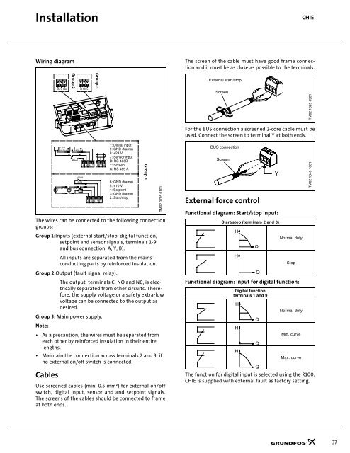
Installation<strong>CHI</strong>EWiring diagramThe screen of the cable must have good frame connectionand it must be as close as possible to the terminals.NC C NOGroup 2N PE LGroup 3External start/stopScreenTM02 1325 0901For the BUS connection a screened 2-core cable must beused. Connect the screen to terminal Y at both ends.The wires can be connected to the following connectiongroups:Group 1:Inputs (external start/stop, digital function,setpoint and sensor signals, terminals 1-9and bus connection, A, Y, B).All inputs are separated from the mainsconductingparts by reinforced insulation.Group 2:Output (fault signal relay).The output, terminals C, NO and NC, is electricallyseparated from other circuits. Therefore,the supply voltage or a safety extra-lowvoltage can be connected to the output asdesired.Group 3: Main power supply.Note:• As a precaution, the wires must be separated fromeach other by reinforced insulation in their entirelengths.• Maintain the connection across terminals 2 and 3, ifno external on/off switch is connected.Cables0-10 V0/4-20 mA 4-20 mA0/10/4-20 mA 0-10 VSTOPRUN10K1 9 8 7B Y A6 5 4 3 21: Digital input9: GND (frame)8: +24 V7: Sensor inputB: RS-485BY: ScreenA: RS 485 A6: GND (frame)5: +10 V4: Setpoint3: GND (frame)2: Start/stopUse screened cables (min. 0.5 mm²) for external on/offswitch, digital input, sensor and and setpoint signals.The screens of the cables should be connected to frameat both ends.Group 1TM02 0795 0101BUS connectionScreenExternal force controlFunctional diagram: Start/stop input:Start/stop (terminals 2 and 3)HHNormal dutyStopFunctional diagram: Input for digital function:Digital functionterminals 1 and 9HHHNormal dutyMin. curveMax. curveThe function for digital input is selected using the R100.<strong>CHI</strong>E is supplied with external fault as factory setting.QQQQQYTM02 1343 100137