design for testability in an application specific dsp - LEDA
design for testability in an application specific dsp - LEDA
design for testability in an application specific dsp - LEDA

Create successful ePaper yourself
Turn your PDF publications into a flip-book with our unique Google optimized e-Paper software.
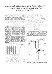
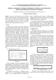
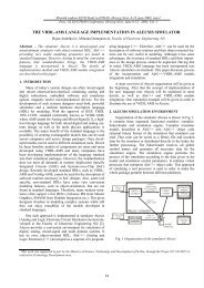
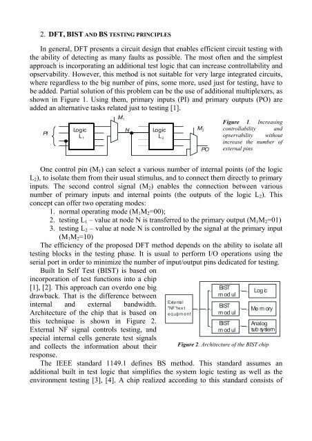
2. DFT, BIST AND BS TESTING PRINCIPLESIn general, DFT presents a circuit <strong>design</strong> that enables efficient circuit test<strong>in</strong>g withthe ability of detect<strong>in</strong>g as m<strong>an</strong>y faults as possible. The most often <strong>an</strong>d the simplestapproach is <strong>in</strong>corporat<strong>in</strong>g <strong>an</strong> additional test logic that c<strong>an</strong> <strong>in</strong>crease controllability <strong>an</strong>dopservability. However, this method is not suitable <strong>for</strong> very large <strong>in</strong>tegrated circuits,where regardless to the big number of p<strong>in</strong>s, some more, used just <strong>for</strong> test<strong>in</strong>g, have tobe added. Partial solution of this problem c<strong>an</strong> be the use of additional multiplexers, asshown <strong>in</strong> Figure 1. Us<strong>in</strong>g them, primary <strong>in</strong>puts (PI) <strong>an</strong>d primary outputs (PO) areadded <strong>an</strong> alternative tasks related just to test<strong>in</strong>g [1].PILog icL 1M1NLog icL 2M2POFigure 1. Increas<strong>in</strong>gcontrollability <strong>an</strong>dopservability without<strong>in</strong>crease the number ofexternal p<strong>in</strong>sOne control p<strong>in</strong> (M 1 ) c<strong>an</strong> select a various number of <strong>in</strong>ternal po<strong>in</strong>ts (of the logicL 2 ), to isolate them from their usual stimulus, <strong>an</strong>d to connect them directly to primary<strong>in</strong>puts. The second control signal (M 2 ) enables the connection between variousnumber of primary <strong>in</strong>puts <strong>an</strong>d <strong>in</strong>ternal po<strong>in</strong>ts (the outputs of the logic L 2 ). Thisconcept c<strong>an</strong> offer two operat<strong>in</strong>g modes:1. normal operat<strong>in</strong>g mode (M 1 M 2 =00);2. test<strong>in</strong>g L 1 – value at node N is tr<strong>an</strong>sferred to the primary output (M 1 M 2 =01)3. test<strong>in</strong>g L 2 – value at node N is controlled by the signal at the primary <strong>in</strong>put(M 1 M 2 =10)The efficiency of the proposed DFT method depends on the ability to isolate alltest<strong>in</strong>g blocks <strong>in</strong> the test<strong>in</strong>g phase. It is usual to per<strong>for</strong>m I/O operations us<strong>in</strong>g theserial port <strong>in</strong> order to m<strong>in</strong>imize the number of <strong>in</strong>put/output p<strong>in</strong>s dedicated <strong>for</strong> test<strong>in</strong>g.Built In Self Test (BIST) is based on<strong>in</strong>corporation of test functions <strong>in</strong>to a chip[1], [2]. This approach c<strong>an</strong> overdo one bigdrawback. That is the difference between<strong>in</strong>ternal <strong>an</strong>d external b<strong>an</strong>dwidth.Architecture of the chip that is based onthis technique is shown <strong>in</strong> Figure 2.External NF signal controls test<strong>in</strong>g, <strong>an</strong><strong>dsp</strong>ecial <strong>in</strong>ternal cells generate test signals<strong>an</strong>d collects the <strong>in</strong><strong>for</strong>mation about theirresponse.External"NF" testequipmentBISTmodulBISTmodulBISTmodulLog icMe m oryAnalogsub systemFigure 2. Architecture of the BIST chipThe IEEE st<strong>an</strong>dard 1149.1 def<strong>in</strong>es BS method. This st<strong>an</strong>dard assumes <strong>an</strong>additional built <strong>in</strong> test logic that simplifies the system logic test<strong>in</strong>g as well as theenvironment test<strong>in</strong>g [3], [4]. A chip realized accord<strong>in</strong>g to this st<strong>an</strong>dard consists of