design for testability in an application specific dsp - LEDA
design for testability in an application specific dsp - LEDA
design for testability in an application specific dsp - LEDA

Create successful ePaper yourself
Turn your PDF publications into a flip-book with our unique Google optimized e-Paper software.
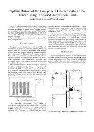
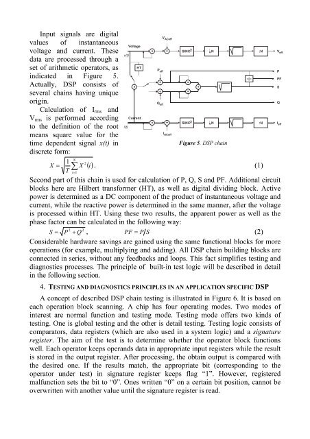
Input signals are digitalvalues of <strong>in</strong>st<strong>an</strong>t<strong>an</strong>eousvoltage <strong>an</strong>d current. Thesedata are processed through aset of arithmetic operators, as<strong>in</strong>dicated <strong>in</strong> Figure 5.Actually, DSP consists ofseveral cha<strong>in</strong>s hav<strong>in</strong>g uniqueorig<strong>in</strong>.Calculation of I rms <strong>an</strong>dV rms is per<strong>for</strong>med accord<strong>in</strong>gto the def<strong>in</strong>ition of the rootme<strong>an</strong>s square value <strong>for</strong> thetime dependent signal x(t) <strong>in</strong>discrete <strong>for</strong>m:v(t)i(t)Voltage+HTCurrent+V ACoff+P off+Q offI ACoffSINC 2 N :NSINC 2 N :NFigure 5. DSP cha<strong>in</strong>N1 2X = ∑ X () i . (1)T i=1Second part of this cha<strong>in</strong> is used <strong>for</strong> calculation of P, Q, S <strong>an</strong>d PF. Additional circuitblocks here are Hilbert tr<strong>an</strong>s<strong>for</strong>mer (HT), as well as digital divid<strong>in</strong>g block. Activepower is determ<strong>in</strong>ed as a DC component of the product of <strong>in</strong>st<strong>an</strong>t<strong>an</strong>eous voltage <strong>an</strong>dcurrent, while the reactive power is determ<strong>in</strong>ed <strong>in</strong> the same m<strong>an</strong>ner, after the voltageis processed with<strong>in</strong> HT. Us<strong>in</strong>g these two results, the apparent power as well as thephase factor c<strong>an</strong> be calculated <strong>in</strong> the follow<strong>in</strong>g way:2 2S = P + Q , PF = P S(2)Considerable hardware sav<strong>in</strong>gs are ga<strong>in</strong>ed us<strong>in</strong>g the same functional blocks <strong>for</strong> moreoperations (<strong>for</strong> example, multiply<strong>in</strong>g <strong>an</strong>d add<strong>in</strong>g). All DSP cha<strong>in</strong> build<strong>in</strong>g blocks areconnected <strong>in</strong> series, without <strong>an</strong>y feedbacks <strong>an</strong>d loops. This fact simplifies test<strong>in</strong>g <strong>an</strong>ddiagnostics processes. The pr<strong>in</strong>ciple of built-<strong>in</strong> test logic will be described <strong>in</strong> detail<strong>in</strong> the follow<strong>in</strong>g section.4. TESTING AND DIAGNOSTICS PRINCIPLES IN AN APPLICATION SPECIFIC DSPA concept of described DSP cha<strong>in</strong> test<strong>in</strong>g is illustrated <strong>in</strong> Figure 6. It is based oneach operation block sc<strong>an</strong>n<strong>in</strong>g. A chip has four operat<strong>in</strong>g modes. Two modes of<strong>in</strong>terest are normal function <strong>an</strong>d test<strong>in</strong>g mode. Test<strong>in</strong>g mode offers two k<strong>in</strong>ds oftest<strong>in</strong>g. One is global test<strong>in</strong>g <strong>an</strong>d the other is detail test<strong>in</strong>g. Test<strong>in</strong>g logic consists ofcomparators, data registers (which are also used <strong>in</strong> a system logic) <strong>an</strong>d a signatureregister. The aim of the test is to determ<strong>in</strong>e whether the operator block functionswell. Each operator keeps oper<strong>an</strong>ds data <strong>in</strong> appropriate <strong>in</strong>put registers while the resultis stored <strong>in</strong> the output register. After process<strong>in</strong>g, the obta<strong>in</strong> output is compared withthe desired one. If the results match, the appropriate bit (correspond<strong>in</strong>g to theoperator under test) <strong>in</strong> signature register keeps flag “1”. However, registeredmalfunction sets the bit to “0”. Ones written “0” on a certa<strong>in</strong> bit position, c<strong>an</strong>not beoverwritten with <strong>an</strong>other value until the signature register is read.V effPPFSQI eff