

Variable permittivity dielectric material loaded stepped-horn antenna
Variable permittivity dielectric material loaded stepped-horn antenna
Variable permittivity dielectric material loaded stepped-horn antenna

You also want an ePaper? Increase the reach of your titles
YUMPU automatically turns print PDFs into web optimized ePapers that Google loves.
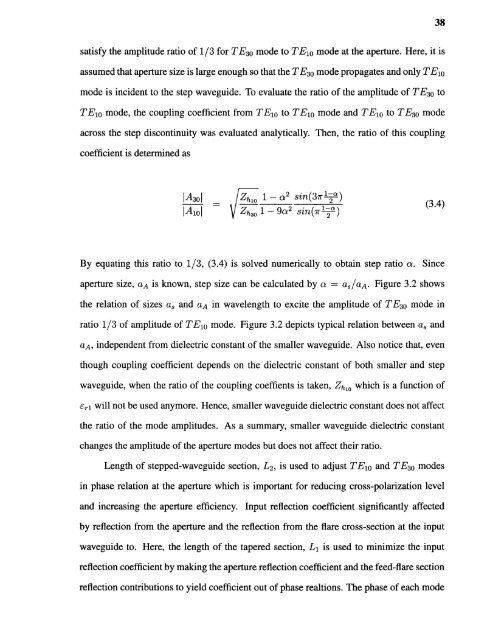
38satisfy the amplitude ratio of 1/3 for TE30 mode to TE10 mode at the aperture. Here, it isassumed that aperture size is large enough so that the TE 30 mode propagates and only TE 10mode is incident to the step waveguide. To evaluate the ratio of the amplitude of TE30 toTE10 mode, the coupling coefficient from TE 10 to TE10 mode and TE10 to TE30 modeacross the step discontinuity was evaluated analytically. Then, the ratio of this couplingcoefficient is determined asBy equating this ratio to 1/3, (3.4) is solved numerically to obtain step ratio a. Sinceaperture size, aA is known, step size can be calculated by a = as/aA. Figure 3.2 showsthe relation of sizes a 3 and aA in wavelength to excite the amplitude of TE 30 mode inratio 1/3 of amplitude of TE 10 mode. Figure 3.2 depicts typical relation between a 3 andaA, independent from <strong>dielectric</strong> constant of the smaller waveguide. Also notice that, eventhough coupling coefficient depends on the <strong>dielectric</strong> constant of both smaller and stepwaveguide, when the ratio of the coupling coeffients is taken, Zh10 which is a function ofεri will not be used anymore. Hence, smaller waveguide <strong>dielectric</strong> constant does not affectthe ratio of the mode amplitudes. As a summary, smaller waveguide <strong>dielectric</strong> constantchanges the amplitude of the aperture modes but does not affect their ratio.Length of <strong>stepped</strong>-waveguide section, L2, is used to adjust TE10 and TE30 modesin phase relation at the aperture which is important for reducing cross-polarization leveland increasing the aperture efficiency. Input reflection coefficient significantly affectedby reflection from the aperture and the reflection from the flare cross-section at the inputwaveguide to. Here, the length of the tapered section, L 1 is used to minimize the inputreflection coefficient by making the aperture reflection coefficient and the feed-flare sectionreflection contributions to yield coefficient out of phase realtions. The phase of each mode


