

Variable permittivity dielectric material loaded stepped-horn antenna
Variable permittivity dielectric material loaded stepped-horn antenna
Variable permittivity dielectric material loaded stepped-horn antenna

You also want an ePaper? Increase the reach of your titles
YUMPU automatically turns print PDFs into web optimized ePapers that Google loves.
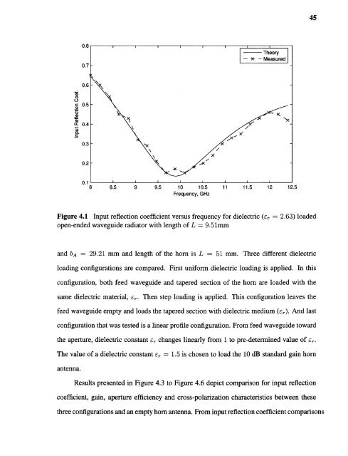
45Figure 4.1 Input reflection coefficient versus frequency for <strong>dielectric</strong> (εr = 2.63) <strong>loaded</strong>open-ended waveguide radiator with length of L = 9.51mmand bA = 29.21 mm and length of the <strong>horn</strong> is L = 51 mm. Three different <strong>dielectric</strong>loading configurations are compared. First uniform <strong>dielectric</strong> loading is applied. In thisconfiguration, both feed waveguide and tapered section of the <strong>horn</strong> are <strong>loaded</strong> with thesame <strong>dielectric</strong> <strong>material</strong>, εr. Then step loading is applied. This configuration leaves thefeed waveguide empty and loads the tapered section with <strong>dielectric</strong> medium (εr). And lastconfiguration that was tested is a linear profile configuration. From feed waveguide towardthe aperture, <strong>dielectric</strong> constant εr changes linearly from 1 to pre-determined value of εr .The value of a <strong>dielectric</strong> constant εr = 1.5 is chosen to load the 10 dB standard gain <strong>horn</strong><strong>antenna</strong>.Results presented in Figure 4.3 to Figure 4.6 depict comparison for input reflectioncoefficient, gain, aperture efficiency and cross-polarization characteristics between thesethree configurations and an empty <strong>horn</strong> <strong>antenna</strong>. From input reflection coefficient comparisons


