

Variable permittivity dielectric material loaded stepped-horn antenna
Variable permittivity dielectric material loaded stepped-horn antenna
Variable permittivity dielectric material loaded stepped-horn antenna

Create successful ePaper yourself
Turn your PDF publications into a flip-book with our unique Google optimized e-Paper software.
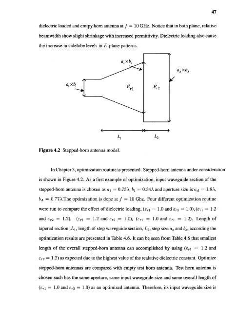
47<strong>dielectric</strong> <strong>loaded</strong> and emtpy <strong>horn</strong> <strong>antenna</strong> at f = 10 GHz. Notice that in both plane, relativebeamwidth show slight shrinkage with increased <strong>permittivity</strong>. Dielectric loading also causethe increase in sidelobe levels in E-plane patterns.Figure 4.2 Stepped-<strong>horn</strong> <strong>antenna</strong> model.In Chapter 3, optimization routine is presented. Stepped-<strong>horn</strong> <strong>antenna</strong> under considerationis shown in Figure 4.2. As a first example of optimization, input waveguide section of the<strong>stepped</strong>-<strong>horn</strong> <strong>antenna</strong> is chosen as al = 0.73A, b 1 = 0.34A and aperture size is aA = 1.8A,bA = 0.77λ.The optimization is done at f = 10 Ghz. Four different optimization routinewere run to compare the effect of <strong>dielectric</strong> loading, (.-r1 E = 1.0 and 5r² = 1.0), (εri = 1.2and 5r² = 1.2), (εri = 1.2 and 5r² = 1.0), (εri = 1.0 and εr1 = 1.2). Length oftapered section ,L 1 , length of step waveguide section, L², step size as and b8 , according theoptimization results are presented in Table 4.6. It can be seen from Table 4.6 that smallestlength of the overall <strong>stepped</strong>-<strong>horn</strong> <strong>antenna</strong> can accomplished by using ( \εri = 1.2 andεr2 =1.2) as expected due to the highest value of the realative <strong>dielectric</strong> constant. Optimize<strong>stepped</strong>-<strong>horn</strong> <strong>antenna</strong>s are compared with empty test <strong>horn</strong> <strong>antenna</strong>. Test <strong>horn</strong> <strong>antenna</strong> ischosen such has the same aperture, same input waveguide size and same overall length of(εri = 1.01 . and 5r² = 1.0) as an optimized <strong>antenna</strong>. Therefore, its input waveguide size is


