Hydraulic Bladder Accumulator Low Pressure
Hydraulic Bladder Accumulator Low Pressure
Hydraulic Bladder Accumulator Low Pressure
- No tags were found...

You also want an ePaper? Increase the reach of your titles
YUMPU automatically turns print PDFs into web optimized ePapers that Google loves.
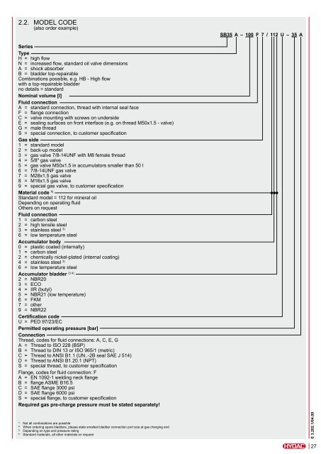
2.2. Model code(also order example)SB35 A – 100 F 7 / 112 U – 35 ASeriesTypeH = high flowN = increased flow, standard oil valve dimensionsA = shock absorberB = bladder top-repairableCombinations possible, e.g. HB - High flowwith a top-repairable bladderno details = standardNominal volume [l]Fluid connectionA = standard connection, thread with internal seal faceF = flange connectionC = valve mounting with screws on undersideE = sealing surfaces on front interface (e.g. on thread M50x1.5 - valve)G = male threadS = special connection, to customer specificationGas side1 = standard model2 = back-up model3 = gas valve 7/8-14UNF with M8 female thread4 = 5/8" gas valve5 = gas valve M50x1.5 in accumulators smaller than 50 l6 = 7/8-14UNF gas valve7 = M28x1.5 gas valve8 = M16x1.5 gas valve9 = special gas valve, to customer specificationMaterial code 1)Standard model = 112 for mineral oilDepending on operating fluidOthers on requestFluid connection1 = carbon steel2 = high tensile steel3 = stainless steel 3)6 = low temperature steel<strong>Accumulator</strong> body0 = plastic coated (internally)1 = carbon steel2 = chemically nickel-plated (internal coating)4 = stainless steel 3)6 = low temperature steel2) 4)<strong>Accumulator</strong> bladder2 = NBR203 = ECO4 = IIR (butyl)5 = NBR21 (low temperature)6 = FKM7 = other9 = NBR22Certification codeU = PED 97/23/ECPermitted operating pressure [bar]ConnectionThread, codes for fluid connections: A, C, E, GA = Thread to ISO 228 (BSP)B = Thread to DIN 13 or ISO 965/1 (metric)C = Thread to ANSI B1.1 (UN..-2B seal SAE J 514)D = Thread to ANSI B1.20.1 (NPT)S = special thread, to customer specificationFlange, codes for fluid connection: FA = EN 1092-1 welding neck flangeB = flange ASME B16.5C = SAE flange 3000 psiD = SAE flange 6000 psiS = special flange, to customer specificationRequired gas pre-charge pressure must be stated separately!1)Not all combinations are possible2)When ordering spare bladders, please state smallest bladder connection port size at gas charging end3)Depending on type and pressure rating4)Standard materials, all other materials on requestE 3.202.1/04.0927