RN Series Data Sheet 10 W SMT DC-DC Wide Input ... - Power-One
RN Series Data Sheet 10 W SMT DC-DC Wide Input ... - Power-One
RN Series Data Sheet 10 W SMT DC-DC Wide Input ... - Power-One

You also want an ePaper? Increase the reach of your titles
YUMPU automatically turns print PDFs into web optimized ePapers that Google loves.
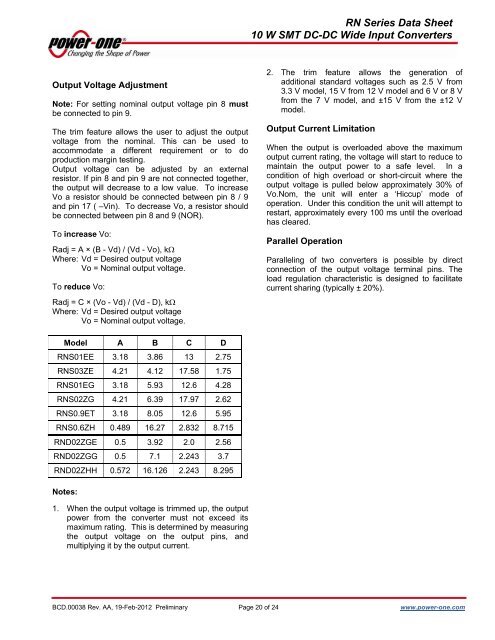
<strong>RN</strong> <strong>Series</strong> <strong>Data</strong> <strong>Sheet</strong><strong>10</strong> W <strong>SMT</strong> <strong>DC</strong>-<strong>DC</strong> <strong>Wide</strong> <strong>Input</strong> ConvertersOutput Voltage AdjustmentNote: For setting nominal output voltage pin 8 mustbe connected to pin 9.The trim feature allows the user to adjust the outputvoltage from the nominal. This can be used toaccommodate a different requirement or to doproduction margin testing.Output voltage can be adjusted by an externalresistor. If pin 8 and pin 9 are not connected together,the output will decrease to a low value. To increaseVo a resistor should be connected between pin 8 / 9and pin 17 ( –Vin). To decrease Vo, a resistor shouldbe connected between pin 8 and 9 (NOR).To increase Vo:Radj = A × (B - Vd) / (Vd - Vo), kΩWhere: Vd = Desired output voltageVo = Nominal output voltage.To reduce Vo:Radj = C × (Vo - Vd) / (Vd - D), kΩWhere: Vd = Desired output voltageVo = Nominal output voltage.2. The trim feature allows the generation ofadditional standard voltages such as 2.5 V from3.3 V model, 15 V from 12 V model and 6 V or 8 Vfrom the 7 V model, and ±15 V from the ±12 Vmodel.Output Current LimitationWhen the output is overloaded above the maximumoutput current rating, the voltage will start to reduce tomaintain the output power to a safe level. In acondition of high overload or short-circuit where theoutput voltage is pulled below approximately 30% ofVo.Nom, the unit will enter a ‘Hiccup’ mode ofoperation. Under this condition the unit will attempt torestart, approximately every <strong>10</strong>0 ms until the overloadhas cleared.Parallel OperationParalleling of two converters is possible by directconnection of the output voltage terminal pins. Theload regulation characteristic is designed to facilitatecurrent sharing (typically ± 20%).Model A B C D<strong>RN</strong>S01EE 3.18 3.86 13 2.75<strong>RN</strong>S03ZE 4.21 4.12 17.58 1.75<strong>RN</strong>S01EG 3.18 5.93 12.6 4.28<strong>RN</strong>S02ZG 4.21 6.39 17.97 2.62<strong>RN</strong>S0.9ET 3.18 8.05 12.6 5.95<strong>RN</strong>S0.6ZH 0.489 16.27 2.832 8.715<strong>RN</strong>D02ZGE 0.5 3.92 2.0 2.56<strong>RN</strong>D02ZGG 0.5 7.1 2.243 3.7<strong>RN</strong>D02ZHH 0.572 16.126 2.243 8.295Notes:1. When the output voltage is trimmed up, the outputpower from the converter must not exceed itsmaximum rating. This is determined by measuringthe output voltage on the output pins, andmultiplying it by the output current.BCD.00038 Rev. AA, 19-Feb-2012 Preliminary Page 20 of 24 www.power-one.com