Information LE030 - Lenz USA
Information LE030 - Lenz USA
Information LE030 - Lenz USA
- No tags were found...
You also want an ePaper? Increase the reach of your titles
YUMPU automatically turns print PDFs into web optimized ePapers that Google loves.
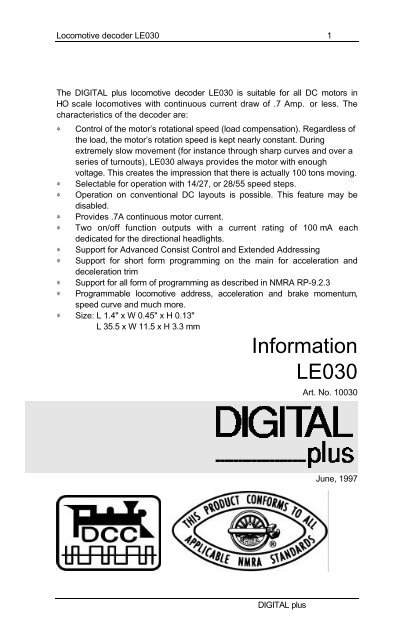
Locomotive decoder <strong>LE030</strong> 1The DIGITAL plus locomotive decoder <strong>LE030</strong> is suitable for all DC motors inHO scale locomotives with continuous current draw of .7 Amp. or less. Thecharacteristics of the decoder are:∗∗∗∗∗∗∗∗∗Control of the motor’s rotational speed (load compensation). Regardless ofthe load, the motor’s rotation speed is kept nearly constant. Duringextremely slow movement (for instance through sharp curves and over aseries of turnouts), <strong>LE030</strong> always provides the motor with enoughvoltage. This creates the impression that there is actually 100 tons moving.Selectable for operation with 14/27, or 28/55 speed steps.Operation on conventional DC layouts is possible. This feature may bedisabled.Provides .7A continuous motor current.Two on/off function outputs with a current rating of 100 mA eachdedicated for the directional headlights.Support for Advanced Consist Control and Extended AddressingSupport for short form programming on the main for acceleration anddeceleration trimSupport for all form of programming as described in NMRA RP-9.2.3Programmable locomotive address, acceleration and brake momentum,speed curve and much more.∗ Size: L 1.4" x W 0.45" x H 0.13"L 35.5 x W 11.5 x H 3.3 mm<strong>Information</strong><strong>LE030</strong>Art. No. 10030June, 1997DIGITAL plus
4 Locomotive decoder <strong>LE030</strong>Some advice on the current draw of the decoderoutput:The current for all the decoder outputs is supplied by an internalrectifier with a maximum current rating of .7 Amps. The sum of allcurrents to the motor and the function outputs cannot exceed thislimit. Each individual output can only draw up to it's limit.Summing up the individual current limits leads to a number largerthan .7 Amps., but they still are not permitted to draw more thanthis limit.Take note of the maximum current load capacity of motoroutput and light outputs. You must ensure that thismaximum current load is not exceeded. In case of anoverload, the decoder will be destroyed!Example:Suppose the motor may require as much as .6 A continuously.Then the directional headlights must not exceed .1 A. Note thatsince only one headlight is on at a time, the headlight outputs arenot additive in this equation.Some advice on installing the decoder:Although the <strong>LE030</strong> has many internal safeguards to preventdamage, you must not allow any metal part of the locomotive totouch the surface components of the decoder. This could cause adirect internal short circuit and the decoder will be destroyed.DO NOT WRAP decoder withelectricians tape or shrink wrap!Doing so will impede air circulation and degrade the performanceof the decoder. Instead, put electrician tape over any part of thelocomotive frame or body that might touch the decoder. This way,you will prevent short circuits without 'suffocating' the decoder.The shrink wrap over a part of the locomotive decoder protectsstatic sensitive parts and must not be removed. Install the decoderusing the provided double sided tape.DIGITAL plus
Locomotive decoder <strong>LE030</strong> 7Any NMRA DCC Command Station, such as the DIGITAL plusLZ100 and a Hand Held LH100 or an Interface LI100, can be usedto program the locomotive decoder <strong>LE030</strong>. With older commandstations (including Arnold or Märklin) the decoder supports indexmode, a special form of register mode which allows you to easilyaddress all the CVs. Using the Arnold Commander 6, or theROCO 'DIGITAL is cool' command station, only register 1(locomotive address) can be set. Many other DCC commandstations support paged programming. The <strong>LE030</strong> supports thismode as well. Details for reading and writing the decoder’sconfiguration variables can be found in the manuals of theappropriate equipment.The configuration variables and their meaningThe new line of <strong>Lenz</strong> advanced decoders, version 5.1, support afull range of features which are set up using a variety ofconfiguration variables. All the configuration variables arenumbered. These numbers are used during programming and areidentical for all decoders that conform to the NMRA standardsindependent of the manufacturer. The following table lists thevarious CVs supported in the <strong>LE030</strong> decoder. Both the New CVnumbers and the older Register numbers are provided for crossreference.Please note: Some CVs (such as CV29) have specific meaningsfor each bit. The bit assignments in this table use a bitnumbering scheme of 1-8 to correspond to the 1-8 display onDIGITAL plus systems. Many other systems use a scheme of 0-7to refer to the individual bits. If you are using such a system youshould subtract one from all bit numbers described in these CVs.DIGITAL plus
8 Locomotive decoder <strong>LE030</strong>Table 1: <strong>LE030</strong> Configuration VariablesCVRegDescription Range Factorysetting1 1 Locomotive address:This is the number with which you select alocomotive in the DIGITAL plus system.2 2 Start voltage:This is the voltage applied to the motor in speed step1. Set this value so that the locomotive just startsmoving in speed step 1.3 3 Acceleration Momentum:Determines the rate of change of speed uponacceleration. A higher value leads to a sloweracceleration.4 4 Brake Momentum:Determines the rate of change of speed upon braking.A higher value leads to longer brake distance.5 - Maximum speedDetermines the maximum speed that the locomotivewill move. This allows you to operate yourlocomotives in a prototypical speed range.- 5 CV29 when the page/pointer register has avalue of 1 or value of CV pointed to by Register6 when register 6 is being used as a pointerregister- 6 Page/Pointer Register:Used during programming for paging or indexing7 7 Version Number:This location stores the version number of thedecoder. This location is read only.8 8 Manufacturers Identification:This value is the manufacturer ID of the decoder,(<strong>Lenz</strong> =99). This location is read only.9 - EMF FrequencyAllows you to adjust the pulse rate frequency for finermotor control1-127 31-15 11-31 11-31 11-10 100-55 40-127 1- 51- 990-15 417 - Extended Address High Byte 192-231 018 - Extended Address Low Byte0-255 0The two byte address if used is contained in CV17+1819 - Consist AddressThe advanced consist address if used is stored in CV190-255 0DIGITAL plus
Locomotive decoder <strong>LE030</strong> 9CV R Description Range Setting29 *5 Decoder Configuration, Byte 1:0-55 4Several decoder properties are set with this byte.Changes are best done in binary mode (see theinformation for the Hand Held LH100). The detailedproperties are:bit 1bit 2locomotive direction:0 = normal: locomotive moves forward whenthe arrow on the Hand Held points up.1 = inverted: locomotive moves forward whenthe arrow on the Hand Held points down.speed step mode:0 = Operation with 14 or 27 speed steps.This setting is selected when the locomotivedecoder is used with a software below version2.0, ROCO-Digital, LGB-Digital, ArnoldDigital and with all other Digital systems thatdo not support the 28 speed step mode.1 = Operation with 28 speed steps.This setting is selected when the locomotivedecoder is used with a Command Station withsoftware version 2.0 or higher. The CommandStation has to be set to 28 speed step mode forthe decoder address, if you are using thissetting!0,1 00,1 0bit 3Other Digital systems supporting the 28 speedstep mode can use the decoder in this setting.Usage on conventional DC layouts:0 locomotive operates in digital mode only0,1 11 locomotive can operate in bothconventional DC and digital mode.bit 4 always 0 0 0bit 5 speed curve:0,1 0bit 6bit 7bit 80 factory pre-set speed curve is used1 user defined speed curve is used. Please enterthe appropriate values into CV 67 to 80 beforesetting this bit.Extended Addressing0= Normal addressing1=Two Byte extended addressingDIGITAL plus0-1 0always 0 0 0
10 Locomotive decoder <strong>LE030</strong>CV R Description Range Setting30 - Decoder Error <strong>Information</strong>bit 1 Motor Short0,1 0bit 2bit 3If set short between motor and trackFront Headlight ShortIf set the front headlight is shortedRear Headlight ShortIf set the rear headlight is shorted60 - Decoder Configuration, byte 2:Similar to CV 29, but other properties are set withthis byte:bit 1bit 2bit 3Back EMF ControlIf set back emf control is activeDecoder Control ActiveIf set CV30 contains decoder errorBrake momentum on DC operation.This setting is only active with conventionalDC operation disabled. (CV 29, bit 3 = 0) Thissetting can be used to achieve prototypicalbraking at red signal indications.0 locomotive proceeds with track voltagedependent speed inside the conventionalsection.0,1 00,1 00,1 10,1 10,1 067 to811 locomotive brakes in the conventionalsection with pre set brake momentum.bits not used4-8- Values for user defined speed curve:These registers are used for a user defined speedcurve. The factory setting for these registers is 0. Ifyou are trying to use this speed curve unmodified,your locomotive will not move!The value in each register determines the velocity ofthe locomotive for each assigned speed step:For the 14 speed step mode, speed step 1 is using thevalue in CV 67, speed step 2 the value in CV 68,speed step 3 the value in CV 69, etc.For the 28 speed step mode, speed step 1 is using thevalue in CV67, speed step 3 the value in CV 68, speedstep 5 the value in CV 69, etc. The intermediatespeed steps are calculated by the decoder.0-63 0DIGITAL plus
Locomotive decoder <strong>LE030</strong> 11Creating a Speed CurveStart by writing down how you want to assign the internal speedsettings to the speed steps, for example by making up a table asshown below. The table shown is just an example and gives thefactory pre-set speed curve for a starting speed of 1.In the following description, we will assume that the decoder isproperly installed and tested, and the locomotive is on theprogramming track with the power on. We assume you are familiarwith the general process of programming using your commandstation.Speed step in14/27 modeWarrantySpeedstep in 28modeInternalspeedsettingCV /register1 1 1 672 3 3 683 5 5 694 7 7 705 9 9 716 11 12 727 13 15 738 15 19 749 17 23 7510 19 28 7611 21 34 7712 23 42 7813 25 52 7914 27 60 80-- 28 63 81<strong>Lenz</strong> GmbH does everything it can do to ensure that its products are free fromdefects and will operate for the life of your model railroad equipment. From timeto time even the best engineered products fail either due to a faulty part or fromaccidental mistakes in installation. To protect your investment in Digital Plusproducts. <strong>Lenz</strong> GmbH offers a very aggressive 10 year Limited Warranty.This warranty is not valid if the user has altered, intentionally misused theDigital Plus product, or removed the product's protection, for example the heatshrink from decoders and other devices. In this case a service charge will beapplied for allDIGITAL plus
12 Locomotive decoder <strong>LE030</strong>repairs or replacements. Should the user desire to alter a Digital Plus Product,they should contact <strong>Lenz</strong> GmbH for prior authorization.Year One: A full repair or replacement will be provided to the originalpurchaser for any item that that has failed due to manufacturer defects orfailures caused by accidental user installation problems. Should the item nolonger be produced and the item is not repairable, a similar item will besubstituted at the manufacturers discretion. The user must pay for shipping toan authorized <strong>Lenz</strong> GmbH warranty center.Year 2 and 3: A full replacement for any item will be provided that has faileddue to manufacturer defects. If the failure was caused by accidental userinstallation or use, a minimal service charge may be imposed. Should the itemno longer be produced and the item is not repairable, a similar item will besubstituted at the manufacturers discretion. The user must pay shipping to andfrom the authorized <strong>Lenz</strong> GmbH warranty center during this portion of thewarranty period.Year 4-10: A minimal service charge will be placed on each item that has faileddue to manufacturer defects and/or accidental user installation problems.Should the item no longer be produced and the item is not repairable, a similaritem will be substituted at the manufacturers discretion. The user must payshipping to and from the authorized <strong>Lenz</strong> GmbH warranty center during thisportion of the warranty period.Please contact your dealer or authorized <strong>Lenz</strong> GmbH warranty center for specificinstructions and current service charges prior to returning any equipment forrepair.Hüttenbergstraße 2935398 Gießen, GermanyHotline: 06403 900 133Fax: 06403 5332http://www.lenz.com<strong>Lenz</strong> Agency of NorthAmericaPO Box 143Chelmsford, MA 01824ph/fax: 978 250 1494support@lenz.comThis equipment complies with Part 15 of FCC Rules. Operation is subject to thefollowing two conditions: (1) this device may not cause harmful interference,and (2) this device must accept any interference received, includinginterference that may cause undesired operation.© 1997 <strong>Lenz</strong> GmbH, All Rights ReservedDIGITAL plus


