Gold Maxi Manual - Lenz USA
Gold Maxi Manual - Lenz USA
Gold Maxi Manual - Lenz USA

You also want an ePaper? Increase the reach of your titles
YUMPU automatically turns print PDFs into web optimized ePapers that Google loves.
<strong>Gold</strong> <strong>Maxi</strong> Locomotive decoder 6locomotive/train covers a settable, defined braking distance. This brakingdistance does not depend on the speed of the locomotive/train.Setting the constant braking distance:The braking distance is defined by the value set in CV52. Since themotors and gear ratios of locomotives vary, the braking distance differsfrom locomotive to locomotive even if the same value is set in CV52.1. Use a short test section to measure how long your locomotive’sbraking distance will be with a given value set in CV52. Start with thedefault value (100) in CV52.2. Enable the constant braking distance function (this requires settingBit 2 in CV50. If this bit is not set, the decoder will use the speeddependentbraking delay).3. Accelerate your locomotive until it has reached average speed.4. At a chosen point in time, set the running notch to 0. This requiresmoving the turning-knob of the manual controls LH30, LH90 or thecompact to the left limit-stop; if you are using the LH100, keeppressing the key until the running notch is set to 0 or until thelocomotive address is displayed (if using the LH100, do not press key! This results in a locomotive-specific emergency stop and thedelays in the locomotive decoder will not be enabled!).5. Measure the covered braking distance.6. Increase or decrease the value in CV52, e.g. in steps of 10, and carryout another measurement. You will thus create a table which willshow the braking distances in relation to the values set in CV52.Important braking distance advice:The constant braking distance is only effective if the running notch isaltered to 0. If the running notch is decreased from e.g. 28 to 10, thespeed-dependent delay from CV4 becomes effective.While the shunting speed is switched off (default setting F3), the constantbraking distance is disabled and the delay from CV4 becomes effective.The constant braking distance is also disabled if the delays set in thedecoder are disabled by means of the corresponding function.The two latter features can also be used sensibly if you wish to interrupt acurrent braking process prematurely.The constant braking distance does not work if the layout is operated inanalogue DC mode.Shunting speedThe shunting speed halves the speed. This facilitates particularly sensitivecontrol of the shunting process. Use function 3 (From the factory setting,can be altered in CV59) to enable and disable the shunting speed. If the6
<strong>Gold</strong> <strong>Maxi</strong> Locomotive decoder 7shunting speed is enabled, the constant braking distance is disabled. Theshunting speed is enabled as long as the function is active.ABC = simple signal stop and slow approachYou can carry out a particularly simple signal stop using the ABC brakingmodule. Depending on the signal position, this module creates anasymmetric track voltage in the braking section in front of the signal. Thedecoder reacts to this. Combined with the constant braking distance,precise on-the-spot stopping in front of red signals is not a problem. Ofcourse, passage in the opposite direction is also possible. The signalindication "slow approach/caution" does not pose a problem; therespective speed can be set in CV53.You can operate all functions during the signal stop or slow approach –you can even reverse away again from the red signal! These special ABCmodules can be used to assemble a very simple block section. Activatethe ABC module by setting Bit 2 (1) in CV51.The ABC feature is not active whenever the shunting speed is switchedon or the delay is disabled.Push-pull train controlA push-pull train control can be set if the ABC braking module is used.There are two different options: push-pull operation with and withoutintermediate stops. The latter also takes slow-approach sections intoaccount.The push-pull train control is activated in CV51, Bit 4 (3) and Bit 5 (4). Thestopping time at the end of the track is set in CV54 (1 to 255 sec).Allocating function outputs to the functions of the digital system(mapping)You can define which digital function is used to switch function outputs FAto FH on or off. Outputs FA to FC can be mapped to function F0(direction-dependent) or functions F1 to F8. Outputs FD and FE can bemapped to function F0 (direction-dependent) or functions F1 to F12.Outputs FF to FH can be mapped to functions F4 to F12.This is allocated in CVs 33 to 46.Lighting effect at function outputsThe lighting effect for the function outputs A and B is set in CV60 and forthe function outputs C and D in CV62. If you wish to switch the effects witha function of the digital system, you can make the allocations to functionsF1 to F8 in CV61 (for function outputs A and B) and CV64 (for functionoutputs C and D). The effects available are shown in the table of thesupported CVs further below.
<strong>Gold</strong> <strong>Maxi</strong> Locomotive decoder 8RailComThe GOLD maxi is equipped with the RailCom function. In addition to thelocomotive address, other data (e.g. speed, CV content) can betransmitted from the locomotive via the track back to the system. Theinformation sent is received by a RailCom detector and then displayed.Which data the decoder is to send is set in CV28. Set Bit 4 in CV29 toenable the transmission function.The S.U.S.I. interfaceThe sound and function interface concept for locomotive decoders wasdevised in 2002 in cooperation with the company DIETZ. The purpose ofthe interface is to facilitate the particularly easy connection of sound andother function modules to locomotive decoders.The S.U.S.I. module receives information about the running notch, thestatus of the functions etc. via the interface and reacts accordingly, forexample the sound of a bell is played or the locomotive sound changes.The quality of these sound effects depends solely on the S.U.S.I. moduleand not on the locomotive decoder!Connecting a S.U.S.I. moduleYou may connect all sound and/or function modules to the S.U.S.I.interface that correspond to the interface's specification. There is a socketfor the connection of a sound or function module – use it to plug in asuitable S.U.S.I (Abb.3, p 6).Setting (programming) the S.U.S.I. moduleLike locomotive decoders, there are also various ways of setting S.U.S.I.modules. These settings are also saved in configuration variables (CVs).If you wish to change these CVs, proceed as if you wanted to change theCVs of the locomotive decoder. The S.U.S.I. module is programmed"through the decoder" as it were. Based on the number of the CV, thelocomotive decoder will know whether the S.U.S.I. module is to beaddressed and will transmit the programming commands via the S.U.S.I.module. Please refer to the operating manual of your module to learnabout the settings possible for your S.U.S.I. module.The settings of the S.U.S.I. module can be carried out both through"Programming in operational mode (PoM)" or "Programming on theprogramming track". When using Digital plus by <strong>Lenz</strong> ® systems, you canchange CVs 1 to 999 with PoM, while "Programming on the programmingtrack" is currently used for CVs 1 to 256. CVs 897 to 1024 have beendefined for the S.U.S.I. module. A special programming method has beenbuilt into this decoder so that these CVs can be reached.In this programming method, CV126 functions as an indicator and CV127as a transport device for the value.8
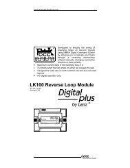
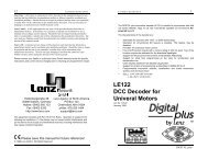
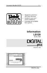
<strong>Gold</strong> <strong>Maxi</strong> Locomotive decoder 9The function sequence is as follows: The target (number of the CV) isentered in the indicator CV126, and the value that is to be transported tothe target is entered in the transport device CV127. If you only wish toread out the target CV, the transport device CV127 is read out after thetarget is entered in CV126.Since only values up to 255 can be entered in a CV, but the CVs forS.U.S.I. start at 897, the CV that functions as the indicator is preset to800. All you have to do is enter the difference between 800 and thedesired target CV, for example number 97 for the target CV897.Example 1: You wish to enter the value 01 in CV897 of the S.U.S.I.module. Proceed as follows:1. Enter 897-800=97 in the indicator CV126.2. Enter the desired value "01" in the transport device CV127. Thedecoder passes the programming command "Enter value "01" in CV"897"" via the S.U.S.I. interface to the connected module.Example 2: You wish to read out the present value of CV902 of theS.U.S.I. module:1. Enter 902-800=102 in the indicator CV126.2. Read out the transport device CV127. The value of CV902 of theconnected module is displayed.BM2M1FBFAU+ext.K.GNDG2G1U+chargeGNDU+FCFDFEFFUSP – Uninterruptable Signal ProcessingIn combination with the optional energy storage, the intelligent USP circuitensures that your locomotive can run even over dirty track sections ordead frogs. The energy storage is not included with this decoder and isinstalled separately in the vehicle.Three terminal screws are provided on the decoder for the connection ofthe energy storage (e.g. Power 1) or a battery circuit.Signal stop and push-pull control with an external reed contactThe GOLD <strong>Maxi</strong> has a connection for an external reed contact. The reedcontact is installed at the bottom of the locomotive. You can let your
<strong>Gold</strong> <strong>Maxi</strong> Locomotive decoder 10locomotive stop in front of a signal or operate in push-pull operation withthe help of a magnet installed in the track. Please see Fig. 4, p. 7 for theconnection of the reed contact.Signal stopTo activate the signal stop via the external reed contact, set bit 7 in CV51.Function sequence: If the locomotive drives over the magnet installed inthe track (reed contact is closed), the locomotive will brake with the delayset in CV4 or the braking distance set in CV52 until it comes to a halt.When the locomotive is to accelerate again, set the speed to speed step 0and accelerate.Emergency stop: If a locomotive drives over a second magnet whilebraking (contact is closed again), it will stop immediately, i.e. without theset delay (or braking distance). This feature can be used as a kind of'INDUSI' by using an electronic magnet as second magnet which is onlyactive when the corresponding signal indicates 'stop'.Push-pull (shuttle) train controlTo activate the push-pull control via the external reed contact, set bits 7and 8 in CV51. In addition, set the desired stopping time in CV54. Youneed a track magnet to activate the reed contact at each end of the pushpullsection.Function sequence: If the locomotive drives over the magnet installed inthe track (reed contact is closed), the locomotive will brake with the delayset in CV4 or the braking distance set in CV52 until it comes to a halt.When the stopping time set in CV54 has elapsed, the locomotive willaccelerate into the opposite direction. Passage over the first magnet(which triggered the braking procedure) is ignored. The locomotive willcontinue until it reaches the magnet at the end of the push-pull section.There, the locomotive will brake again, wait for the set stopping time toelapse, change ist direction of travel, and continue in this direction – andthe game starts all over again.Programming the decoderThe locomotive address, acceleration and deceleration delay, and allother features of the locomotive decoder can be changed as often asdesired by reprogramming the decoder. The features are "stored"permanently in special locations even when the operational voltage isswitched off. These locations are called "configuration variables" or simply"CV". The values are configured electronically, which means that it is notnecessary to open the locomotive again after the decoder has beeninstalled.The <strong>Gold</strong> <strong>Maxi</strong> decoder supports all forms of NMRA defined service modeprogramming. To program a <strong>Gold</strong> <strong>Maxi</strong> decoder you will need a systemcapable of service mode programming (such as Set-90 or Set-100).Please note that not all systems support the programming of all CVs.10
<strong>Gold</strong> <strong>Maxi</strong> Locomotive decoder 11You can also alter the content of CVs both through "Programming inoperational mode (PoM)" (except for CV1, CV17 and CV18) or"Programming on the programming track".For detailed instructions on how to program using the above-mentioneddevices, please refer to the operating manuals which accompany thosedevices.The factory default for the decoders address is address 3 running in 28speed step mode. The decoder can be used with these basicconfigurations immediately after purchase. All configurations can, ofcourse, be changed at any later date.Resetting the decoderIf you wish to reset all the decoder CVs to the factory default setting, entervalue 33 or a value of 8 in CV8. The CVs of a connected S.U.S.I. moduleare not reset!
<strong>Gold</strong> <strong>Maxi</strong> Locomotive decoder 143 (2) 1 ABC direction-dependency deactivated 04 (3) 1 Activate push-pull operation without intermediate 0stop5 (4) 1 Activate push-pull operation with intermediate 0stop6 (5) 1 Stopping with DC independent of the polarity 0(only if Bit 3 is deleted in CV29).7 (6) 1 Signal stop activated with external contact 08 (7) 1 Push-pull operation activated with external0contact52 0-255 Braking distance with activated constant braking 50distance53 0-255 Slow approach with ABC 4854 0-255 Stopping time in push-pull operation, 1 to 256 sec 455 0-255 Sets brightness at function outputs A and C,255255=max56 0-255 Sets brightness at function outputs B and D,255255=max57-59Function mapping:Each bit of the CV stands for a function of the digitalsystem: Bit 1(0) for function 1, Bit 2(1) for function 2and so on up to Bit 8(7) for function 8. If you wish toallocate a function to the dimming, the respective bitmust be set.57 0-255 Dimming (no From the factory setting) 058 0-255 Shunting speed (From the factory setting F3) 459 0-255 Switching off the delay (From the factory setting F4) 860 0-255 Lighting effect at function outputs A and B. The units 0digit of the value stands for function output A, thetens digit for function output B:0 No effect1 Marslight2 Gyrolight3 Strobe4 Double strobe61 0-255 Function mapping: lighting effect at function outputs 0A and B62 0-255 Lighting effect at function outputs C and D. 0The tens digit of thevalue stands forfunction output D:0 No effect1 Flashing at sametime as functionoutput CThe units digit of the valuestands for function output C:0 No effect1 Flashing2 Flickering type 1 (smooth)3 Dimming with value fromCV552 Flashingalternately tofunction output C3 Flickering type 214
<strong>Gold</strong> <strong>Maxi</strong> Locomotive decoder 15(less smooth)4 Flickering type 3(excitedly)5 Dimming withvalue from CV5663 Flashing frequency for function outputs C and D:default approx. 1 sec, f = 1 / ( 0.03 * (1 + CV63))64 Function mapping: lighting effect at function outputsC and D0-255 Values for characteristic speed line, default = Fromthe factory speed line67..94105 0-255 User Identification #1 255106 0-255 User Identification #2 25516112 0-255 Duration of motor timeout when track signal hasstopped.t = CV112 * 0.016sec, default approx. 0.25 sec113 0-255 Minimum PWM value, control for motor types 4 or 5 30114 0-255 Change duty cycle for motor type 4 or 5 10115 6-30 Asymmetrical DCC sensitivity 12126 0-255 CV (indicator) for S.U.S.I., offset 800 102127 0-255 CV (transport device) for S.U.S.I. 0128 Service number (Please read out the number) -2320
<strong>Gold</strong> <strong>Maxi</strong> Locomotive decoder 16North American Warranty<strong>Lenz</strong> GmbH does everything it can do to ensure that its products are free fromdefects and will operate for the life of your model railroad equipment. From time totime even the best engineered products fail either due to a faulty part or fromaccidental mistakes in installation. To protect your investment in Digital plusproducts, <strong>Lenz</strong> GmbH offers a very aggressive 10 year Limited Warranty.This warranty is not valid if the user has altered, intentionally misused the DigitalPlus product, or removed the product's protection, for example the heat shrink fromdecoders and other devices. In this case a service charge will be applied for allrepairs or replacements. Should the user desire to alter a Digital Plus Product, theyshould contact <strong>Lenz</strong> GmbH for prior authorization.Year One: A full repair or replacement will be provided to the original purchaser forany item that that has failed due to manufacturer defects or failures caused byaccidental user installation problems. Should the item no longer be produced andthe item is not repairable, a similar item will be substituted at the manufacturer’sdiscretion. The user must pay for shipping to an authorized <strong>Lenz</strong> GmbH warrantycenter.Year 2 and 3: A full replacement for any item will be provided that has failed dueto manufacturer defects. If the failure was caused by accidental user installation oruse, a minimal service charge may be imposed. Should the item no longer beproduced and the item is not repairable, a similar item will be substituted at themanufacturer’s discretion. The user must pay shipping to and from the authorized<strong>Lenz</strong> GmbH warranty center during this portion of the warranty period.Year 4-10: A minimal service charge will be placed on each item that has faileddue to manufacturer defects and/or accidental user installation problems. Shouldthe item no longer be produced and the item is not repairable, a similar item will besubstituted at the manufacturer’s discretion. The user must pay shipping to andfrom the authorized <strong>Lenz</strong> GmbH warranty center during this portion of the warrantyperiod.Please contact your dealer or authorized <strong>Lenz</strong> GmbH warranty center for specificinstructions and current service charges prior to returning any equipment for repair.Hüttenbergstraße 2935398 Gießen, GermanyHotline: 06403 900 133Fax: 06403 900155info@digital-plus.dehttp://www.lenz.com<strong>Lenz</strong> Agency of North AmericaPO Box 143Chelmsford, MA 01824ph: 978 250 1494fax: 978 455 LENZsupport@lenz.comThis equipment complies with Part 15 of FCC Rules. Operation is subject to thefollowing two conditions: (1) this device may not cause harmful interference, and(2) this device must accept any interference received, including interference thatmay cause undesired operation.Please save this manual for future reference!© 2006 <strong>Lenz</strong> GmbH, All Rights Reserved16