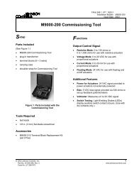
Tech Sheet for Miscellaneous Controls (VF5602-42AA-NEW)
Tech Sheet for Miscellaneous Controls (VF5602-42AA-NEW)
Tech Sheet for Miscellaneous Controls (VF5602-42AA-NEW)

You also want an ePaper? Increase the reach of your titles
YUMPU automatically turns print PDFs into web optimized ePapers that Google loves.
Sensor Installation6IntroductionThis section describes the proper wiring, installation and sighting considerations<strong>for</strong> all sensors that can be used with a Veri-Flame.WarningIncorrect sensor installation may cause the sensor to generatea false flame signal, possibly resulting in the collection ofunburned fuel in the combustion chamber. This unburnedfuel creates the potential <strong>for</strong> explosions which can result ininjuries, death and property damage. Be certain that theflame sensor detects acceptable pilot and main flames only.Sensor WiringFlame RodsRoute sensor wiring a sufficient distance from ignition and other high voltageor high current wiring to avoid electrical interference. Interference from groundcurrents, nearby conductors, radio-frequency emitters (wireless divices), andinverter drives can induce false flame signals. Shielded cables can help reduceinterference with the shield connected to ground at the control end only. Thewire type and its capacitance (picofarads or microfarads) to ground may causelow signal problems, so a grounded shield may decrease the signal due to thecable’s internal capacitance. Multiple U.V. tube-type sensor leads run togetherwithout shielding may interfere or “cross talk”, so the shield or flexible armormust be grounded to prevent this situation. For flame rod sensor runs approximately100 feet (30 meters) or greater, use Eclipse part number 21741coax cable. To achieve the maximum wiring distance, the shield should not begrounded (keep in mind that an ungrounded shield provides less protectionagainst electrical interference).Note:Unshielded sensor wiring must not be run in common with other wires; itmust be run in separate conduit. Multiple unshielded flame sensorwiring must not be run together <strong>for</strong> long lengths in a common conduit orwireway. Use #14 to #18 AWG wire suitable <strong>for</strong> 90°C (194°F) and 600volt insulation, or a better grade if required by the application. Multipleshielded flame sensor cables can be run in a common conduit.Flame rods should be used only on gas burners. They accumulate soot from oilburners, causing nuisance shutdowns and unsafe operating conditions.See the burner manufacturer’s literature <strong>for</strong> flame rod mounting location. Wheninstalling flame rods, please consider the following:24Eclipse Veri-Flame Instruction Manual 818-6/06