GEMINI 52 Manual 1379KB - Red Lion Controls
GEMINI 52 Manual 1379KB - Red Lion Controls
GEMINI 52 Manual 1379KB - Red Lion Controls

You also want an ePaper? Increase the reach of your titles
YUMPU automatically turns print PDFs into web optimized ePapers that Google loves.
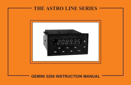
THE ASTRO LINE SERIES<strong>GEMINI</strong> <strong>52</strong>00 INSTRUCTION MANUAL
TABLE OF CONTENTSI. GENERAL DESCRIPTION 2A) Safety Summary 2B) Programming The Gemini <strong>52</strong>00 2C) Programming The Personality 2D) Programming The Presets, Scale Factors, Timed Output Values 3-4E) Factory Settings 5-6F) Operator Accessible Functions With Programming Disabled 7G) Diagnostics, Self-Test, & “Watchdog” Timer 7H) Input Circuitry & Set-up 8I) Overflow Indication 8II. PROGRAMMING THE <strong>GEMINI</strong> <strong>52</strong>00 IN DUAL RATE WITHOUT DISPLAY C MODE 9A) Codes 41, 42, 43, 44, 45, & 46 9-10B) Codes 51, <strong>52</strong>, 53, 54, 55, & 56 10-12C) Codes 61, 62, 63, 64, 65, 66, Preset Values, & Scale Factors A&B 12-14III. PROGRAMMING THE A/B, (A-B)/B, & A-B DISPLAY C MODES 15A) Basic Operation 15B) Codes 41, 42, 43, 45, & 46 15-16C) Codes 51, <strong>52</strong>, 53, 54, & 55 16-18D) Codes 61, 62, 63, 64, 65, 66, Preset Values, & Scale Factors A&B 18-20E) Gemini <strong>52</strong>00 Programming Example - Speed Ratio Application 21-22IV. <strong>GEMINI</strong> <strong>52</strong>00 20 MA CURRENT LOOP COMMUNICATIONS 23A) Communication Format 23B) Sending Commands & Data To The Gemini <strong>52</strong>00 24-25C) Receiving Data From The Gemini <strong>52</strong>00 26D) Print Options 26E) Current Loop Installation 27F) Communications Application 28G) Troubleshooting Gemini Serial Communications & Serial Loop-Back Self-Test 29V. APPENDIX “A” - INSTALLATION & INPUT CONFIGURATION SWITCH SET-UP 30-37VI. APPENDIX “B” - SPECIFICATIONS & DIMENSIONS 38-39VII. APPENDIX “C” - TROUBLESHOOTING GUIDE 40-41VIII. APPENDIX “D” - DUAL RATE W/O DISP C FUNCTION COMMAND CODE SUMMARY 42-45IX. APPENDIX “E” - <strong>GEMINI</strong> <strong>52</strong>00 DUAL RATE W/DISP C FUNCTION COMMAND CODE SUMMARY 46-49X. APPENDIX “F” - SCALING FOR RATE & DISPLAY C 50-<strong>52</strong>XI. APPENDIX “G” - <strong>GEMINI</strong> <strong>52</strong>00 PROGRAMMING CHARTS 53-56XII. APPENDIX “H” - ORDERING INFORMATION 57-1-
FACTORY SETTINGS [Cont’d]DUAL RATE WITH SPEED DIFF. FACTORY SETTINGS *Keys Struck Display Description4,1 41 3 Personality selected as DUAL RATE W/SPEED DIFF.4,2 42 3 Reset Rate A&Boutputs4,3 43 1 Rate B Conversion Factor is Rate Per Second (x1)4,5 45 4 Rate B Scale Multiplier of 1.04,6 46 1 Display C leading zero blanking and no decimal point5,1 51 1 Output 1 assigned to Rate A, Output 2 to Rate B5,2 <strong>52</strong> 3 Output 1 terminates at Reset, Normal Phase5,3 0000.10 Timed Output 1 value of 0.1 Sec.5,4 54 3 Output 2 terminates at Reset, Normal Phase5,5 0000.10 Timed Output 2 value of 0.1 Sec.6,2 62 1 Rate A Conversion Factor is Rate per Second (x1)6,3 63 1 Rate Minimum Update Time of 0.5 Sec.6,4 64 4 Rate A Scale Multiplier of 16,5 65 1 RateA&Bleading zero blanking, no decimal point6,6 66 1 No functions except Reset enabled3 01.0000 Scale Factor A (Rate A) set to 1.00003 01.0000 Scale Factor B (Rate B) set to 1.00001 000500 Preset 1 set to 5002 001000 Preset 2 set to 1000* If [41 1] is changed to [41 2], then the factory settings are as shown.DUAL RATE WITH SPEED DRAW FACTORY SETTINGS *Keys Struck Display Description4,1 41 4 Personality selected as DUAL RATE W/SPEED DRAW4,2 42 3 Reset Rate A&Boutputs4,3 43 1 Rate B Conversion Factor is Rate Per Second (x1)4,5 45 4 Rate B Scale Multiplier of 1.04,6 46 1 Display C leading zero blanking and no decimal point5,1 51 1 Output 1 assigned to Rate A, Output 2 to Rate B5,2 <strong>52</strong> 3 Output 1 terminates at Reset, Normal Phase5,3 0000.10 Timed Output 1 value of 0.1 Sec.5,4 54 3 Output 2 terminates at Reset, Normal Phase5,5 0000.10 Timed Output 2 value of 0.1 Sec.6,1 61 1 Display C Multiplier of 16,2 62 1 Rate A Conversion Factor is Rate per Second (x1)6,3 63 1 Rate Minimum Update Time of 0.5 Sec.6,4 64 4 Rate A Scale Multiplier of 16,5 65 1 RateA&Bleading zero blanking, no decimal point6,6 66 1 No functions except Reset enabled3 01.0000 Scale Factor A (Rate A) set to 1.00003 01.0000 Scale Factor B (Rate B) set to 1.00001 000500 Preset 1 set to 5002 001000 Preset 2 set to 1000* If [41 1] is changed to [41 2], then the factory settings are as shown.-6-
OPERATOR ACCESSIBLE FUNCTIONS WITHPROGRAMMING DISABLEDOne of the important features of the Gemini <strong>52</strong>00 is the ability to disableprogramming. With this ability, accidental bumping of the keys or tampering byunauthorized personnel can be prevented. However, it may be necessary to allowreset and certain programming functions, such as Presets and Scale FactorValues, to be changed in daily operation. The Gemini <strong>52</strong>00, through the use of the“Operator Accessible Functions” modes, can enable these functions even whenthe “PGM. DIS.” terminal is connected to “COMMON”.The “Operator Accessible Functions” modes are programmed by entering atwo-digit function code (66) and the desired mode. Unlike other function codes,the mode does not take effect immediately. The “PGM. DIS.” terminal must beconnected to “COMMON” in order for the Gemini to disable programming andoperate as per the mode programmed.There are four basic “Operator Accessible Functions” Modes available. Thesemodes enable the following functions.1. NO FUNCTIONS EXCEPT RESET ENABLED - In this mode, manualreset is enabled, but none of the programming functions can be changed.However, the functions can be interrogated.2. PRESET PROGRAMMING AND RESET ENABLED - The entire frontpanel is disabled with the exceptions of Preset programmability and manualreset. All functions can be interrogated.3. SCALE FACTOR PROGRAMMING AND RESET ENABLED - Theentire front panel is disabled with the exceptions of Scale Factorprogrammability and manual reset. All functions can be interrogated.4. SCALE FACTOR AND PRESET PROGRAMMING, AND RESETENABLED - The entire front panel is disabled with the exceptions of ScaleFactor and Preset programmability, and manual reset. All functions can beinterrogated.All of these modes can be modified with the addition of a “-” sign. The minussign disables the manual reset, at the front panel and the remote reset (RST., notRST.A) terminal, at the rear of the unit.There is also a rear panel DIP switch which permits disabling of the front panelreset button. This is independent of the rear terminal remote reset, and can be used inconjunction with any front panel disable mode. The combination of a manual andremote reset inputs provides a high level of security without sacrificing flexibility.DIAGNOSTICS, SELF-TEST, & “WATCHDOG” TIMERThe security of the Gemini <strong>52</strong>00 is further enhanced by its self-test diagnosticand “watchdog” timer capabilities.The diagnostics are concerned with the special, no power memory of theGemini <strong>52</strong>00. Whenever the power is turned off, all pertinent function settingsand measurements are automatically saved. When power is restored, thefunctions and data are re-instated. This allows you to program the unit once andnot have to re-program it until you wish to use it in another mode.When the function codes and data are saved, computations are made withthese values. The result of these computations is stored in the memory to serve asa check against possible error. On power up, the same computations are repeatedon the stored data. If the results do not agree with the stored results, a “P” willappear on the left side of the display. If this occurs, refer to the “TroubleshootingGuide” for directions.The Gemini <strong>52</strong>00 also contains a “watchdog” timer. In order to insure thesoftware is functioning properly, the program constantly monitors itself. If theproper sequence and timing of internal events does not occur, an “E” will appearon the left side of the display. If this occurs, refer to the “Troubleshooting Guide”for directions.The final type of built-in check, is the front panel initiated self-test. It can beperformed at any time, even when the Gemini <strong>52</strong>00 is running. It will notinterfere with the accumulation of counts or control functions. A function code of“6”, “+/-” starts the test. At this time, whatever was displayed will disappear andbe replaced by a string of decimal points and the overflow indicator. Then thedisplay will show a string of 9’s, then 8’s etc., until a string of 0’s are shown. Theself-test will then turn off the overflow indicator and activate the minus “-” sign.Then the unit shows an interlace pattern of -010101, then -212121, followed by-232323 etc., until -898989 is reached. At this time the outputs can be tested bypressing the “1” or “2” key. (The program disable pin must be disconnected inorder to allow activation of the outputs.) An automatic exit will take place aftersix seconds or immediately if the Program Disable terminal is connected tocommon. Normal length of display time for each of the patterns is approximately0.5 sec. Rapidly pressing “E” during self-test can speed up the sequence.-7-
INPUT CIRCUITRY & SET-UPThere are two independent input channels on the Gemini <strong>52</strong>00. Various typesof sensor outputs can be accommodated by appropriate DIP switch set-up. Theseinclude: TTL or CMOS logic, current sinking, current sourcing, dry contact ormagnetic pickup.Both Input Channels A and B consist of a logic input and a separate low levelmagnetic pickup input. For a complete detailed description of input set-up, seeAppendix “A”.OVERFLOW INDICATIONThe Gemini <strong>52</strong>00 features an overflow indicator (LED) which is located to the leftof the sixth digit and above the polarity annunciator. This LED will turn on if thecapacity of the display (6-digits) is exceeded or if the following conditions occur.Upon power-up, the display will go to zero, and the overflow LED will turn on.The overflow LED is turned on to indicate that the zero on the display is not ameasured value. The overflow LED will turn off after the Gemini <strong>52</strong>00completes its rate measurement. It will take 16 seconds if the rate is zero.The overflow LED can also turn on when the rate input frequency exceeds themaximum 3250 cps allowed for a rate update period of 16 sec. See Code 63 -“Rate Minimum Update Time”.-8-
PROGRAMMING THE <strong>GEMINI</strong> <strong>52</strong>00 IN DUAL RATE WITHOUT DISPLAY C MODEThe rate indicators use a time interval method (1/tau) to calculate the ratevalue. This method enables high resolution at all input rates. The unit countsinput pulses and after a programmable minimum update time has occurred, itwaits until the next count edge occurs, takes the elapsed time and number ofedges, and calculates the rate value. At slower rates, averaging can beaccomplished by programming the “Minimum Update Time” (0.5 sec. to 16 sec.)for the desired response. Extensive scaling capabilities allow practically anydesired reading at very slow count rates.In the Dual Rate, without Display C mode, the two rate indicators operate in anindependent non-synchronized fashion. Input A serves as the input to the Rate Aindicator and Input B serves as the input to the Rate B indicator. All modes areindependently selected for each rate channel.CODE 41 - UNIT PERSONALITYThe unit personality mode is the first function code that is programmed. Thismode will determine the basic operational characteristics of the unit. Thisprogramming section deals with the unit programmed as a Dual Rate Indicatorwithout Display C, mode 1. The “Programming The A/B, (A-B)/B, And A-BDisplay C Modes” section covers programming of the Gemini <strong>52</strong>00 when in UnitPersonality modes 2, 3, and 4.Once the Unit Personality mode is changed, the factory settings willautomatically be loaded into the unit’s memory. This provides a known startingplace. If at any point, it is desired to return to the factory settings for the currentmode, the unit personality is called up, a minus is put in front of the mode bypressing the “+/-” key, and the “E” key is pushed to load the factory settings. Thefactory settings are listed on page 5 and 6.[41 1] DUAL RATE INDICATION - In this mode, the Gemini <strong>52</strong>00 operates astwo independent rate indicators.[41 2] DUAL RATE WITH A/B DISPLAY C-Inthis unit personality, theGemini <strong>52</strong>00 operates as a dual rate indicator with an A/B display C function.See “Programming The A/B, (A-B)/B, And A-B Display C Modes” section forprogramming details.[41 3] DUAL RATE WITH A-B DISPLAY C-Inthis unit personality, theGemini <strong>52</strong>00 operates as a dual rate indicator with an (A-B) Display Cfunction. See “Programming The A/B, (A-B)/B, And A-B Display C Modes”section for programming details.[41 4] DUAL RATE WITH (A-B)/B DISPLAYC-Inthis unit personality, theGemini <strong>52</strong>00 operates as a dual rate indicator with an (A-B)/B Display Cfunction. See “Programming The A/B, (A-B)/B, And A-B Display C Modes”section for programming details.[41 -1][41 -2] A minus indicator preceding the mode will cause[41 -3] the factory settings to be loaded when entered.[41 -4]CODE 42 - RESET KEY & TERMINAL ACTUATION MODESThe Reset Button & Terminal Actuation Modes controls the effect that thereset button and terminal have on the two display channels. Resetting will notaffect the rate displays or update period in any manner. Reset only affects theoutput(s) associated with the rate channels.There is a separate “Rst A” terminal provided which makes it possible toindependently reset both the Rate A and B Outputs.[42 1] RESET RATE A OUTPUT(S)[42 2] RESET RATE B OUTPUT(S)[42 3] RESET RATE A&BOUTPUTSCODE 43 - RATE B CONVERSION FACTORThe Rate B Conversion Factor is used to convert Display B to indicate rate inthe desired time unit. See Appendix “F” - Scaling For Rate And Display C.[43 1] Rate Per Second (x1)[43 2] Rate Per Minute (x60)[43 3] Rate Per Hour (x3600)-9-
CODE 44 - RATE B MINIMUM/MAXIMUM UPDATE TIMEThe determination of the rate value uses a method in which the elapsed time ismeasured between the first and last pulse of the update period. The minimumupdate time is the shortest the time period can be. Once the minimum update timehas expired, the unit will end the measurement period when the next negativegoing count edge occurs. If the unit does not receive the next negative count edgewithin the maximum update time at the start of the measurement period, the unitwill end the time period and the rate display will go to zero. At very slow countrates the update time period will be the actual period of one count cycle.[44 1] 0.5 Sec. minimum/1 Sec. maximum[44 2] 1 Sec. minimum/2 Secs. maximum[44 3] 2 Secs. minimum/4 Secs. maximum[44 4] 4 Secs. minimum/8 Secs. maximum[44 5] 8 Secs. minimum/16 Secs. maximum (max. rate = 7500 cps)[44 6] 16 Secs. minimum/32 Secs. maximum (max. rate = 3250 cps)CODE 45 - RATE B SCALE MULTIPLIERThe Rate B Scale Multiplier is used in conjunction with the Rate Scale FactorB and Rate B Conversion Factor to scale the actual signal input to obtain thedesired reading.[45 1] x 1000[45 2] x 100[45 3] x10[45 4] x1[45 5] x 0.1[45 6] x 0.01CODE 46 - RATE B DECIMAL POINT & LEADING ZEROBLANKINGThere are six basic modes of decimal point placement for the Rate B indicatorof the Gemini <strong>52</strong>00. The decimal point is placed to the right of the display digitthat corresponds to the mode identifier. (The right most decimal point, digit 1, isnever turned on.) A “-” sign in front of the mode identifier will inhibit leadingzero blanking. The absence of a “-” sign will enable leading zero blanking.[46 1] 0[46 2] 0.0[46 3] 0.0 0 LEADING ZERO[46 4] 0.0 0 0 BLANKING[46 5] 0.0000[46 6] 0.00000[46 -1] 000000[46 -2] 00000.0[46 -3] 0 0 0 0.0 0 LEADING ZERO[46 -4] 0 0 0.0 0 0 BLANKING INHIBITED[46 -5] 00.0000[46 -6] 0.00000CODE 51 - OUTPUT ASSIGNMENTThe outputs of the Gemini <strong>52</strong>00 can be assigned to either the Rate A or Rate Bchannel or one to each.The Gemini <strong>52</strong>00 has a Preset tracking feature which allows Preset 1 to trackPreset 2. If Preset tracking is programmed, whenever the Preset 2 value is changed,the Preset 1 value will also change to maintain the same offset. For example, ifPreset 1 is 100 and Preset 2 is 200, changing Preset 2 to 300 will automaticallychange Preset 1 to 200, maintaining the same 100 unit offset. In order to change theamount of offset, the Preset 1 value is changed. The Preset tracking feature isprogrammed by adding a “-” modifier in front of the desired mode.Note: When Preset tracking is enabled, before changing Preset 2 via serialcommunications, the Preset 2 value must be interrogated in order to establishthe Preset 1 value.[51 1] Output 1 assigned to Rate A, Output 2 assigned to Rate B[51 2] Outputs 1&2assigned to Rate B[51 3] Outputs 1&2assigned to Rate A[51 -1][51 -2] These modes are the same as above with the exception[51 -3] that Preset Tracking is enabled.-10-
CODE <strong>52</strong> - OUTPUT 1 TERMINATION MODESThe Gemini <strong>52</strong>00 has four “Output 1 termination Modes” which control theway Output 1 will terminate or reset. In all modes, Output 1 will terminateimmediately when the channel to which it is assigned is manually reset.A reverse phase mode is available on the Gemini <strong>52</strong>00. This refers to thecomplementing of the logic state of Output 1. With normal phase operation,when the display value reaches Preset 1, Output 1 will turn on. The resetcondition of Output 1 is output off. In reverse phase operation, Output 1 turns offwhen Preset 1 is reached. The reset condition of Output 1 is output on. (Note: Thestate of the relay, if used, is also reversed.) A “-” sign in front of the modeidentifier will provide for reverse phase operation. The absence of a “-” sign willindicate normal phase operation.[<strong>52</strong> 3] TERMINATE AT MANUAL RESET - Output 1 activates when the rate isgreater than or equal to the Preset 1 value. In this mode, once Output 1 isactivated, it does not deactivate until the moment a manual reset occurs.Output 1 is set for normal phase operation.[<strong>52</strong> 4] TERMINATE AT MANUAL RESET END - This mode is like thepreceding, except Output 1 deactivates when reset ends. Output 1 is set fornormal phase operation.[<strong>52</strong> 5] TERMINATE AFTER TIMED OUTPUT1-Ifboth outputs are assigned tothe same rate channel [51 2,3], Output 1 will activate when the rate is below orequal to the Preset 1 value. If each output is assigned to a different channel [51 1],Output 1 will activate when the rate is greater than or equal to the Preset 1 Value.Output 1 will terminate after the “Timed Output 1 Value” if the timed outputvalue is less than the update time of the rate channel. If the timed output value isgreater than the update time, the output will appear to be latched on, deactivatingwhen the rate drops below the Preset [51 1], or above the Preset [51 2,3] and theoutput time expires. Output 1 is set for normal phase operation.[<strong>52</strong> 6] BOUNDARY MODE - When in boundary mode, the Preset 1 Value servesas the boundary point. When the rate value is less than Preset 1, Output 1 is notactivated (normal phase). When the rate value is greater than or equal to thePreset, Output 1 is activated. If the display value were to drop below Preset 1,Output 1 would then deactivate. Output 1 is set for normal phase operation.[<strong>52</strong> -3][<strong>52</strong> -4] These modes are the same as above with the exception[<strong>52</strong> -5] that Output 1 is set for reverse phase operation.[<strong>52</strong> -6]CODE 53 - TIMED OUTPUT 1 VALUEThe Gemini <strong>52</strong>00 has the capability of varying the Timed Output 1 value from0.01 second to 599.99 seconds. When the code is entered, instead of a single modeidentifier digit being displayed, six digits will be shown. Refer to the “ProgrammingThe Presets, Scale Factors, And Timed Output Values” section for more detailsabout entering. The timed output will be terminated if the unit is manually reset.The Timed Output 1 Value is used only when in timed output terminationmode, [<strong>52</strong> 5].Note: A Timed Output Value of zero cannot be programmed into the Gemini <strong>52</strong>00.If a value of 0 is entered into the display and the “E” key is pressed, the unit willnot enter the 0, but will stay in the data entry mode. If a new value is not entered,it will time out and the unit will continue to use its previous setting.CODE 54 - OUTPUT 2 TERMINATION MODESThe Gemini <strong>52</strong>00 has four “Output 2 termination Modes” which control theway Output 2 will terminate or reset. In all modes Output 2 will terminateimmediately when the channel to which it is assigned is manually reset.A reverse phase mode is available on the Gemini <strong>52</strong>00. This refers to thecomplementing of the logic state of Output 2. With normal phase operation,when the display value reaches Preset 2, Output 2 will turn on. The resetcondition of Output 2 is output off. In reverse phase operation, Output 2 turns offwhen Preset 2 is reached.The reset condition of Output 2 is output on. (Note: The state of the relay, if used,is also reversed.) A “-” sign in front of the mode identifier will provide for reversephase operation. The absence of a “-” sign will indicate normal phase operation.-11-
CODE 54 - OUTPUT 2 TERMINATION MODES (Cont’d)[54 3] TERMINATE AT MANUAL RESET - Output 2 activates when the rate isgreater than or equal to the Preset 2 value. In this mode, once Output 2 isactivated, it does not deactivate until the moment a manual reset occurs.Output 2 is set for normal phase operation.[54 4] TERMINATE AT MANUAL RESET END - This mode is like thepreceding, except Output 2 deactivates when reset ends. Output 2 is set fornormal phase operation.[54 5] TERMINATE AFTER TIMED OUTPUT 2 - Output 2 will activate whenthe rate is greater than or equal to the Preset 2 Value and will terminate after the“Timed Output 2 Value” expires. This will occur every update time period forwhich the above condition is true. If the output duration time is greater than theupdate time, Output 2 will appear to be latched on, deactivating when the ratedrops below the Preset and the output time expires. Output 2 is set for normalphase operation.[54 6] BOUNDARY MODE - When in boundary mode, the Preset 2 Value servesas the boundary point. When the rate value is less than Preset 2, Output 2 is notactivated (normal phase). When the rate value is greater than or equal to Preset2, Output 2 is activated. If the display value were to drop below Preset 2,Output 2 would then deactivate. Output 2 is set for normal phase operation.[54 -3][54 -4] These modes are the same as above with the exception[54 -5] that Output 2 is set for reverse phase operation.[54 -6]CODE 55 - TIMED OUTPUT 2 VALUEThe Gemini <strong>52</strong>00 has the capability of varying the timed output from 0.01second to 599.99 seconds. When the code is entered, instead of a single modeidentifier digit being displayed, six digits will be shown. Refer to “ProgrammingThe Presets, Scale Factors, And Timed Output Values” section for more detailsabout entering. Timed Output 2 will be terminated if the unit is manually reset.The Timed Output 2 Value is used only when in timed output terminationmode, [54 5].Note: A Timed Output Value of zero cannot be programmed into the Gemini <strong>52</strong>00.If a value of 0 is entered into the display and the “E” key is pressed, the unit willnot enter the 0, but will stay in the data entry mode. If a new value is not entered,it will time out and the unit will continue to use its previous setting.CODE 56 - RATE B RIGHT HAND DUMMY ZEROSDummy zeros can be used to alleviate display fluctuations due to an unstable inputsignal. These zeros effectively move significant digits to the left. Therefore, a normalrate display of 1 could be shown as a 10, 100, or 1000. Using the dummy zeros willmake it necessary to adjust the scaling if they were not considered before.[56 1] 1 RIGHT HAND DUMMY ZERO[56 2] 2 RIGHT HAND DUMMY ZEROS[56 3] 3 RIGHT HAND DUMMY ZEROS[56 4] NO RIGHT HAND DUMMY ZEROSCODE 61 - RATE A RIGHT HAND DUMMY ZEROSDummy zeros can be used to alleviate display fluctuations due to an unstable inputsignal. These zeros effectively move significant digits to the left. Therefore, a normalrate display of 1 could be shown as a 10, 100, or 1000. Using the dummy zeros willmake it necessary to adjust the scaling if they were not considered before.[61 1] 1 RIGHT HAND DUMMY ZERO[61 2] 2 RIGHT HAND DUMMY ZEROS[61 3] 3 RIGHT HAND DUMMY ZEROS[61 4] NO RIGHT HAND DUMMY ZEROSCODE 62 - RATE A CONVERSION FACTORThe Rate A Conversion Factor is used to convert Display A to indicate rate inthe desired time unit. See Appendix “F” - Scaling For Rate And Display C.[62 1] Rate Per Second (x1)[62 2] Rate Per Minute (x60)[62 3] Rate Per Hour (x3600)-12-
CODE 63 - RATE A MINIMUM/MAXIMUM UPDATE TIMEThe determination of the rate value uses a method in which the elapsed time ismeasured between the first and last pulse of the update period. The minimumupdate time is the shortest the time period can be. Once the minimum update timehas expired, the unit will end the measurement period when the next negativegoing count edge occurs. If the unit does not receive the next negative count edgewithin the maximum update time at the start of the measurement period, the unitwill end the time period and the rate display will go to zero. At very slow countrates, the update time period will be the actual period of one count cycle.[63 1] 0.5 Sec. minimum/1 Sec. maximum[63 2] 1 Sec. minimum/2 Secs. maximum[63 3] 2 Secs. minimum/4 Secs. maximum[63 4] 4 Secs. minimum/8 Secs. maximum[63 5] 8 Secs. minimum/16 Secs. maximum (max. rate = 7500 cps)[63 6] 16 Secs. minimum/32 Secs. maximum (max. rate = 3250 cps)CODE 64 - RATE A SCALE MULTIPLIERThe Rate A Scale Multiplier is used in conjunction with the Rate Scale FactorA and Rate A Conversion Factor to scale the actual signal input to obtain thedesired reading.[64 1] x 1000[64 2] x 100[64 3] x10[64 4] x1[64 5] x 0.1[64 6] x 0.01CODE 65 - RATE A DECIMAL POINT & LEADING ZEROBLANKINGThere are six basic modes of decimal point placement for the Rate A indicatorof the Gemini <strong>52</strong>00. The decimal point is placed to the right of the display digitthat corresponds to the mode identifier. (The right most decimal point, digit 1, isnever turned on.) A “-” sign in front of the mode identifier will inhibit leadingzero blanking. The absence of a “-” sign will enable leading zero blanking.[65 1] 0[65 2] 0.0[65 3] 0.0 0 LEADING ZERO[65 4] 0.0 0 0 BLANKING[65 5] 0.0000[65 6] 0.00000[65 -1] 000000[65 -2] 00000.0[65 -3] 0 0 0 0.0 0 LEADING ZERO[65 -4] 0 0 0.0 0 0 BLANKING INHIBITED[65 -5] 00.0000[65 -6] 0.00000CODE 66 - “OPERATOR ACCESSIBLE FUNCTIONS” MODESThe Gemini <strong>52</strong>00 has four basic levels of “Operator Accessible Functions”.Each of these levels can be modified to enable or disable manual reset. When the“PGM. DIS.” (program disable) terminal is connected to “COMMON”, accessto all functions is disabled except for those listed below which will remainenabled. All of the function codes and parameters can be interrogated, regardlessof the “Operator Accessible Functions” mode selected.A “-” sign in front of the mode identifier will disable the front panel Resetbutton and the “RST.” terminal.Note: The front panel reset button can be independently disabled by using thedisable reset DIP switch.[66 1] NO FUNCTIONS ENABLED EXCEPT RESET - In this mode, manualreset is enabled, but none of the programming functions can be changed.[66 2] PRESET PROGRAMMING AND RESET ENABLED - In this mode,manual reset and the programming of the Preset Values are enabled.[66 3] SCALE FACTOR PROGRAMMING AND RESET ENABLED - In thismode, manual reset and the programming of the Scale Factors are enabled.[66 4] SCALE FACTOR, PRESET PROGRAMMING & RESET ENABLED -In this mode, manual reset and the programming of the Scale Factor and PresetValues are enabled.-13-
CODE 66 - “OPERATOR ACCESSIBLE FUNCTIONS” MODES (Cont’d)[66 -1][66 -2] These Modes are the same as above with the[66 -3] exception that manual reset is disabled.[66 -4]PRESET VALUESWhenever the display value equals the Preset 1 or 2 Value, an output actionwill occur. This action depends on the previously programmed modes. ThePreset Values may vary from -999,999 to 999,999. Refer to “Programming ThePresets, Scale Factors, And Timed Output Values” section for instructions onentering the Preset Values.“1” - PRESET 1 VALUE“2” - PRESET 2 VALUESCALE FACTORS A&B“3” SCALE FACTOR - The Scale Factor, for whichever Value (Rate A or B)is currently being displayed, is accessed by pressing the “3” key. To access theScale Factor of the “other” rate display value, the “+/-” key would be pushed (tochange the display to the other value), then the “3” key would be pushed. Theactual rate (in pps) is multiplied by the Scale Factor, Scale Multiplier, and RateConversion factor to obtain the desired display reading. The Scale Factor is usedprimarily for conversion from existing pulses per unit of measure to the requireddisplayed units. This includes conversion from different units of measure (i.e feetto meters, etc.). The Scale Factor Values may range from 0.0001 to 5.9999. Referto “Programming The Presets, Scale Factors, And Timed Output Values” sectionfor instructions on entering the Scale Factor Values.-14-
PROGRAMMING THE A/B, (A-B)/B, AND A-B DISPLAY C MODESThis section will deal with the programming and operation of the Gemini <strong>52</strong>00in the modes which include Display C, [41 2,3,4]. Since all three display C modesare very similar in operation, they will all be covered in one section.BASIC OPERATIONIn all of the display C modes, the Gemini <strong>52</strong>00 performs a mathematicalcalculation using Rate channels A&Btoobtain the Display C value.The two rate indicators, use a time interval method (1/tau) to calculate the ratevalue. This method enables high resolution at all input rates. The unit countsinput pulses and after a programmable minimum update time has occurred, itwaits until the next count edge occurs, takes the elapsed time and number ofedges, and calculates the rate value. At slower rates, averaging can beaccomplished by programming the “Minimum Update Time” (0.5 sec. to 16 sec.)for the desired response.When operating in any of the three modes which utilize display C, the two rateindicators will synchronize themselves in order to obtain an accurate display Creading. The Gemini <strong>52</strong>00 will determine which channel is running at the slowerrate, and it will use that channel to synchronize the other channel. This is done sothat both time measurement windows are as close as possible. Because it isnecessary to keep the measurement windows the same, there is only one RateMinimum Update Time setting. The slower channel will determine the updatetime for the other rate channel and Display C.If one rate input signal drops out before the update period has completed, thatchannel will go to zero after the maximum update time has expired. The channelwill then continually time-out according to the maximum update time that wasselected in Code 63, until a rate signal again appears on its input. After the firsttime-out, the other channel, which still has a rate signal on its input, will thenbegin to operate in a non-synchronous manner, updating according to the“Minimum Update Time” and its input frequency. It will not synchronize withthe channel that timed-out, and has an update period of 16 seconds.The Display C channel, however, will only update according to themaximum update time because it is calculated based on both of the ratechannels. The rate channels will again synchronize when both channels have arate signal on their inputs.CODE 41 - UNIT PERSONALITYThe unit personality mode is the first function code that is programmed. Thismode will determine the basic operational characteristics of the unit. Thisprogramming section deals with the unit personality programmed as a Dual RateIndicator with Display C, modes 2, 3, or 4. A separate section, “ProgrammingThe Gemini <strong>52</strong>00 In Dual Rate Without Display C Mode” goes over theprogramming of the Gemini <strong>52</strong>00 when programmed in mode 1.Whenever the Unit Personality mode is changed, the factory settings willautomatically be loaded into the unit’s memory. This provides a known startingplace. If at any point, it is desired to return to the factory settings for the currentpersonality, the unit personality is called up, a minus is put in front of the mode bypressing the “+/-” key, and the “E” key is pushed to load the factory settings.[41 1] DUAL RATE INDICATION - In this Unit Personality, the Gemini <strong>52</strong>00operates as two independent rate indicators. See “Programming The Gemini<strong>52</strong>00 In Dual Rate Without Display C Mode” section for programming details.[41 2] DUAL RATE WITH A/B DISPLAY C - In this unit personality, theGemini <strong>52</strong>00 operates as a dual rate indicator with an A/B (Speed Ratio)Display C function.[41 3] DUAL RATE WITH A-B DISPLAY C - In this unit personality, theGemini <strong>52</strong>00 operates as a dual rate indicator with an A-B (Speed Difference)Display C function.[41 4] DUAL RATE WITH (A-B)/B DISPLAY C - In this unit personality, theGemini <strong>52</strong>00 operates as a dual rate indicator with an (A-B)/B (Speed Draw)Display C function.[41 -1][41 -2] A minus indicator preceding the mode will cause[41 -3] the factory settings to be loaded when entered.[41 -4]-15-
CODE 42 - RESET BUTTON & TERMINAL ACTUATIONMODESThe Reset Button & Terminal Actuation modes control the effect that the resetbutton and terminal have on the two display channels. Resetting will not affectthe rate displays in any manner. Reset only affects the output(s) associated withthe rate channels.There is a separate “Rst A” terminal provided which makes it possible toindependently reset both Rate A and B channels.[42 1] RESET RATE A OUTPUT(S)[42 2] RESET RATE B OUTPUT(S)[42 3] RESET RATE A&BOUTPUT(S)[42 4] RESET DISPLAY C OUTPUT(S)[42 5] RESET DISPLAY C AND RATE A OUTPUT(S)[42 6] RESET DISPLAY C AND RATE B OUTPUT(S)CODE 43 - RATE B CONVERSION FACTORThe Rate B Conversion Factor is used to convert Display B to indicate rate inthe desired time unit. See Appendix “F” - Scaling For Rate And Display C.[43 1] Rate Per Second (x1)[43 2] Rate Per Minute (x60)[43 3] Rate Per Hour (x3600)CODE 45 - RATE B SCALE MULTIPLIERThe Rate B Scale Multiplier is used in conjunction with the Rate Scale FactorB and Rate B Conversion Factor to scale the actual signal input to obtain thedesired reading.[45 1] x 1000[45 2] x 100[45 3] x10[45 4] x1[45 5] x 0.1[45 6] x 0.01CODE 46 - DISPLAY C DECIMAL POINT & LEADING ZEROBLANKINGThere are six basic modes of decimal point placement for the Display Cindicator of the Gemini <strong>52</strong>00. The decimal point is placed to the right of the displaydigit that corresponds to the mode identifier. (The right most decimal point, digit 1,is never turned on.) A “-” sign in front of the mode identifier will inhibit leadingzero blanking. The absence of a “-” sign will enable leading zero blanking.[46 1] 0[46 2] 0.0[46 3] 0.0 0 LEADING ZERO[46 4] 0.0 0 0 BLANKING[46 5] 0.0000[46 6] 0.00000[46 -1] 000000[46 -2] 00000.0[46 -3] 0 0 0 0.0 0 LEADING ZERO[46 -4] 0 0 0.0 0 0 BLANKING INHIBITED[46 -5] 00.0000[46 -6] 0.00000CODE 51 - OUTPUT ASSIGNMENTThe outputs of the Gemini <strong>52</strong>00 can be assigned to the Rate A, Rate B, or theDisplay C channel.The Gemini <strong>52</strong>00 has a Preset tracking feature which allows Preset 1 to trackPreset 2. If Preset tracking is programmed, whenever the Preset 2 value is changed,the Preset 1 value will also change to maintain the same offset. For example, if Preset1 is 100 and Preset 2 is 200, changing Preset 2 to 300 will automatically changePreset 1 to 200, maintaining the same 100 unit offset. In order to change the amountof offset, the Preset 1 value is changed. The Preset tracking feature is programmed byadding a “-” modifier in front of the desired mode.-16-
Note: When Preset tracking is enabled, before changing Preset 2 via serialcommunications, the Preset 2 value must be interrogated in order to establishthe Preset 1 value.[51 1] Output 1 assigned to Rate A, Output 2 assigned to Rate B[51 2] Outputs 1&2assigned to Rate B[51 3] Outputs 1&2assigned to Rate A[51 4] Output 1 assigned to Rate B, Output 2 assigned to Display C[51 5] Output 1 assigned to Rate A, Output 2 assigned to Display C[51 6] Output 1&2assigned to Display C[51 -1][51 -2][51 -3] These modes are the same as above with the[51 -4] exception that Preset Tracking is enabled.[51 -5][51 -6]CODE <strong>52</strong> - OUTPUT 1 TERMINATION MODESThe Gemini <strong>52</strong>00 has four “Output 1 termination Modes” which control theway Output 1 will terminate or reset. In all modes, Output 1 will terminateimmediately when the channel to which it is assigned is manually reset.A reverse phase mode is available on the Gemini <strong>52</strong>00. This refers to thecomplementing of the logic state of Output 1. With normal phase operation,when the display value reaches Preset 1, Output 1 will turn on. The resetcondition of Output 1 is output off. In reverse phase operation, Output 1 turns offwhen Preset 1 is reached. The reset condition of Output 1 is output on. (Note: Thestate of the relay, if used, is also reversed.) A “-” sign in front of the modeidentifier will provide for reverse phase operation. The absence of a “-” sign willindicate normal phase operation.[<strong>52</strong> 3] TERMINATE AT MANUAL RESET - Output 1 activates when the rateor display value is greater than or equal to the Preset 1 value. In this mode, onceOutput 1 is activated, it does not deactivate until the moment a reset occurs.Output 1 is set for normal phase operation.[<strong>52</strong> 4] TERMINATE AT MANUAL RESET END - This mode is like thepreceding, except Output 1 deactivates when reset ends. Output 1 is set fornormal phase operation.[<strong>52</strong> 5] TERMINATE AFTER TIMED OUTPUT1-Ifboth outputs are assignedto the same channel [51 2,3,6], Output 1 will activate when the rate or displayvalue is below or equal to the Preset 1 value. If each output is assigned to adifferent channel [51 1,4,5], Output 1 will activate when the rate or displayvalue is greater than or equal to the Preset 1 Value.Output 1 will terminate after the “Timed Output 1 Value” if the Timed OutputValue is less than the update time of the rate or display channel. If the TimedOutput 1 Value is greater than the programmed update time, Output 1 willappear to be latched on, deactivating when the rate or display value dropsbelow the Preset [51 1,4,5], or above the Preset [51 2,3,6] and the output timeexpires. Output 1 is set for normal phase operation.[<strong>52</strong> 6] BOUNDARY MODE - When in boundary mode, the Preset 1 Valueserves as the boundary point. When the rate or display value is less than Preset1, Output 1 is not activated (normal phase). When the rate or display value isgreater than or equal to Preset 1, Output 1 is activated. If the display value wereto drop below Preset 1, Output 1 would then deactivate. Output 1 is set fornormal phase operation.[<strong>52</strong> -3][<strong>52</strong> -4] These modes are the same as above with the exception[<strong>52</strong> -5] that Output 1 is set for reverse phase operation.[<strong>52</strong> -6]CODE 53 - TIMED OUTPUT 1 VALUEThe Gemini <strong>52</strong>00 has the capability of varying Timed Output 1 from 0.01second to 599.99 seconds. When the code is entered, instead of a single modeidentifier digit being displayed, six digits will be shown. Refer to “ProgrammingPresets, Scale Factors, and Timed Output Values” section for more details aboutentering. The timed output will be terminated if the unit is manually reset.The Timed Output 1 Value is used only when in timed output terminationmode, [<strong>52</strong> 5].Note: A Timed Output Value of zero cannot be programmed into the Gemini <strong>52</strong>00.If a value of 0 is entered into the display and the “E” key is pressed, the unit willnot enter the 0, but will stay in the data entry mode. If a new value is not entered,it will time out and the unit will continue to use its previous setting.-17-
CODE 54 - OUTPUT 2 TERMINATION MODESThe Gemini <strong>52</strong>00 has four “Output 2 termination Modes” which control theway Output 2 will terminate or reset. In all modes, Output 2 will terminateimmediately when the channel to which it is assigned to is manually reset.A reverse phase mode is available on the Gemini <strong>52</strong>00. This refers to thecomplementing of the logic state of Output 2. With normal phase operation,when the display value reaches Preset 2, Output 2 will turn on. The resetcondition of Output 2 is output off. In reverse phase operation, Output 2 turns offwhen Preset 2 is reached. The reset condition of Output 2 is output on. (Note: Thestate of the relay, if used, is also reversed.) A “-” sign in front of the modeidentifier will provide for reverse phase operation. The absence of a “-” sign willindicate normal phase operation.[54 3] TERMINATE AT MANUAL RESET - Output 2 activates when the rate ordisplay value is greater than or equal to the Preset 2 value. In this mode, onceOutput 2 is activated, it does not deactivate until the moment a reset occurs.Output 2 is set for normal phase operation.[54 4] TERMINATE AT MANUAL RESET END - This mode is like thepreceding, except Output 2 deactivates when reset ends. Output 2 is set fornormal phase operation.[54 5] TERMINATE AFTER TIMED OUTPUT 2 - Output 2 will activate whenthe rate or display value is greater than or equal to the Preset 2 Value and willterminate after the “Timed Output 2 Value” expires. This will occur everyupdate time period for which the above condition is true. If the Output 2duration time is greater than the display update time, the output will appear tobe latched on, deactivating when the rate or display value drops below Preset 2and the output time expires. Output 2 is set for normal phase operation.[54 6] BOUNDARY MODE - When in boundary mode, the Preset 2 Valueserves as the boundary point. When the rate or display value is less than Preset2, Output 2 is not activated (normal phase). When the rate or display value isgreater than or equal to Preset 2, Output 2 is activated. If the display value wereto drop below Preset 2, Output 2 would then deactivate. Output 2 is set fornormal phase operation.[54 -3][54 -4] These modes are the same as above with the exception[54 -5] that Output 2 is set for reverse phase operation.[54 -6]CODE 55 - TIMED OUTPUT 2 VALUEThe Gemini <strong>52</strong>00 has the capability of varying the Timed Output 2 Value from0.01 second to 599.99 seconds. When the code is entered, instead of a singlemode identifier digit being displayed, six digits will be shown. Refer to“Programming Presets, Scale Factors, and Timed Output Values” section formore details about entering. Timed Output 2 will be terminated if the unit ismanually reset.The Timed Output 2 Value is used only when in timed output terminationmode, [54 5].Note: A Timed Output Value of zero cannot be programmed into the Gemini <strong>52</strong>00.If a value of 0 is entered into the display and the “E” key is pressed, the unit willnot enter the 0, but will stay in the data entry mode. If a new value is not entered,it will time out and the unit will continue to use its previous setting.CODE 61 - DISPLAY C MULTIPLIERThe Display C Multiplier is used in the Speed Ratio [41 2] and Draw [41 4]modes to obtain the desired amount of resolution for Display C. For example; ifDisplay C is indicating speed ratio, and both rates are the same, the ratio would be1. By using a Display C Multiplier of 10, 100, 1,000 or 10,000, in conjunctionwith the proper decimal point, the ratio could be read in tenths, hundredths,thousandths or ten thousandths respectively.The Display C Multiplier is not available in the Speed Difference UnitPersonality [41 3].[61 1] x1[61 2] x10[61 3] x100[61 4] x1,000[61 5] x10,000-18-
CODE 62 - RATE A CONVERSION FACTORThe Rate A Conversion Factor is used to convert Display A to indicate rate inthe desired time unit. See Appendix “F” - Scaling For Rate And Display C.[62 1] Rate Per Second (x1)[62 2] Rate Per Minute (x60)[62 3] Rate Per Hour (x3600)CODE 63 - RATE MINIMUM/MAXIMUM UPDATE TIMEThe determination of the rate value uses a method in which the elapsed time ismeasured between the first and last pulse of the update period. In the Display Cmodes [41 2,3,4], the rate channels are synchronized. The slower of the twochannels will determine the minimum update time. The minimum update time isthe shortest the time period can be. Once the minimum update time has expired,the unit will end the measurement period, for the synchronizing channel, whenthe next negative going count edge occurs. If the unit does not receive the nextnegative count edge within the maximum update time at the start of themeasurement period, the unit will end the time period and calculate the rate basedupon the amount of pulses received during the time period. After thesynchronizing channel ends its measurement period, the other channel will endits measurement period when it receives the next negative going edge.[63 1] 0.5 Sec. minimum/1 Sec. maximum[63 2] 1 Sec. minimum/2 Secs. maximum[63 3] 2 Secs. minimum/4 Secs. maximum[63 4] 4 Secs. minimum/8 Secs. maximum[63 5] 8 Secs. minimum/16 Secs. maximum (max. rate = 7500 cps)[63 6] 16 Secs. minimum/32 Secs. maximum (max. rate = 3250 cps)[64 1] x 1000[64 2] x 100[64 3] x10[64 4] x1[64 5] x 0.1[64 6] x 0.01CODE 65 - RATE A&BDECIMAL POINT & LEADING ZEROBLANKINGThere are six basic modes of decimal point placement for the Rate A&Bindicators of the Gemini <strong>52</strong>00. The decimal point is placed to the right of thedisplay digit that corresponds to the mode identifier. (The right most decimal point,digit 1, is never turned on.) A “-” sign in front of the mode identifier will inhibitleading zero blanking. The absence of a “-” sign will enable leading zero blanking.[65 1] 0[65 2] 0.0[65 3] 0.0 0 LEADING ZERO[65 4] 0.0 0 0 BLANKING[65 5] 0.0000[65 6] 0.00000[65 -1] 000000[65 -2] 00000.0[65 -3] 0 0 0 0.0 0 LEADING ZERO[65 -4] 0 0 0.0 0 0 BLANKING INHIBITED[65 -5] 00.0000[65 -6] 0.00000CODE 64 - RATE A SCALE MULTIPLIERThe Rate A Scale Multiplier is used in conjunction with the Rate Scale FactorA and Rate A Conversion Factor to scale the actual signal input to obtain thedesired reading.-19-
CODE 66 - “OPERATOR ACCESSIBLE FUNCTIONS” MODESThe Gemini <strong>52</strong>00 has four basic levels of “Operator Accessible Functions”.Each of these levels can be modified to enable or disable manual reset. When the“PGM. DIS.” (Program Disable) terminal is connected to “COMMON”, accessto all functions is disabled, except for those listed below, which will remainenabled. All of the function codes and parameters can be interrogated, regardlessof the “Operator Accessible Functions” mode selected.A “-” sign in front of the mode identifier will disable the front panel Resetbutton and the “RST.” terminal.Note: The front panel reset button can be independently disabled by using thedisable reset DIP switch.[66 1] NO FUNCTIONS ENABLED EXCEPT RESET - In this mode, manualreset is enabled, but none of the programming functions can be changed.[66 2] PRESET PROGRAMMING AND RESET ENABLED - In this mode,manual reset and the programming of the Preset Values are enabled.[66 3] SCALE FACTOR PROGRAMMING AND RESET ENABLED - In thismode, manual reset and the programming of the Scale Factor Values areenabled.[66 4] SCALE FACTOR, PRESET PROGRAMMING AND RESETENABLED - In this mode, manual reset and the programming of the ScaleFactors and Preset Values are enabled.SCALE FACTORS A&BThe Scale Factor, for whichever Value (Rate A or B) is currently beingdisplayed, is accessed by pressing the “3” key. To access the Scale Factor of the“other” display value, the “+/-” key would be pushed (to change the display to theother value), then the “3” key would be pushed. If the “3” key is pushed while theDisplay C value is on the display, a scale factor will not be displayed, since theDisplay C value does not have a scale factor associated with it.The actual rate (in pps) is multiplied by the appropriate Scale Factor, ScaleMultiplier, and Rate Conversion factor to obtain the desired display reading. TheScale Factor is used primarily for conversion from existing pulses per unit ofmeasure to the required displayed units. This includes conversion from differentunits of measure (i.e feet to meters, etc.). The Scale Factor Value may range from0.0001 to 5.9999. Refer to “Programming the Presets, Scale Factors, And TimedOutput Values” section for entering instructions.“3” - SCALE FACTOR[66 -1][66 -2] These modes are the same as above with the[66 -3] exception that manual reset is disabled.[66 -4]PRESET VALUESWhenever the rate or display value equals the Preset Value, an output action willoccur. This action depends on the previously programmed modes. The PresetValue may vary from -999,999 to 999,999. Refer to “Programming the Presets,Scale Factors, And Timed Output Values” section for entering instructions.“1” - PRESET 1 VALUE“2” - PRESET 2 VALUE-20-
<strong>GEMINI</strong> <strong>52</strong>00 PROGRAMMING EXAMPLE - SPEED RATIOA paper towel manufacturer needs to maintain a tight control on the speedrelationship of two rollers. Two outputs are needed to signal when the speedrelationship of the rolls are out of the operating “safe zone”. A 72 tooth gear ismounted on each of the rolls. Two LMPC’s are used to sense the gear teeth. Eachof the rolls have a circumference of 2 feet.The Gemini <strong>52</strong>00 can fulfill all the requirements of the system. The Gemini<strong>52</strong>00 can provide an indication of the speed relationship, and can also provide aFeet per Minute indication of the speed at which each of the rolls are running.The system can be set-up so that the speed relationship is given as a speed ratioor draw. After programming, only the Presets will have to be changed. In thisprogramming example, Display C will be set-up to indicate speed ratio, A/B.SCALING THE RATE CHANNELSSince both of the rolls have the same circumference and have gears with thesame number of teeth, the scaling parameters obtained will apply to both Ratechannels A&B.The unit of display for the rate channels will be in feet. From the informationgiven, 72 pulses will be provided for 2 “Display Units” (feet) of linear web travel.Utilizing the formulas and procedure in Appendix “F”, we obtain the TotalScaling Factor required, “K T ”.K T = Display Units/Number of PulsesK T = 2/72 = 0.0277777To provide maximum conversion accuracy, a Scale Multiplier value of 0.01 ischosen to give the largest number of significant digits possible for the Scale Factor.SF=K T /SCMSF = 0.027777/0.01 = 2.7778The Rate A & Rate B Scale Factors will be programmed for 2.7778 and thecorresponding Scale Multipliers will be programmed for 0.01.The final scaling parameter that needs to be selected is the “Rate ConversionFactors” for both of the Rate channels. To achieve rate in Feet Per Minute, the“Rate Conversion Factor”, Rate Per Minute is selected.-21-
SCALING DISPLAY CScaling Display C is simply a matter of choosing the amount of decimal pointresolution that is desired for the application. This is accomplished by selecting aDisplay C Multiplier and by programming the desired “Display C DecimalPoint” location. To obtain Display C resolution in thousandths, a “Display CMultiplier” of 1000 is used. For example; If both rolls are operating at the samespeed, the ratio would be 1. Selecting a “Display C Multiplier” of 1000 and adecimal point to the right of digit 4, will result in a Display C readout of 1.000.HARDWARE SET-UPThe application drawing shows how the hardware for the system isconfigured. The Input to both rate channels will be LMPC open collector LogicMagnetic Pickups. The A & B Input channels will therefore, be set-upidentically. The dip switch settings for various types of sensors are shown inAppendix “A”. The “EN/DIS RST.” DIP switch position, is set to the “DIS.”position to disable the use of the front panel reset button. The solid state opencollector outputs of the Gemini, “O1-SNK” and “O2-SNK”, are connected to thespeed control circuitry of the system.STEP BY STEP PROGRAMMING PROCEDURESTEP 1 - Select function code 41 (Unit Personality). Select and enter mode 2 fora Dual rate with speed ratio unit personality.Note: Function code 42, “Reset Button & Terminal Actuation Modes” is notprogrammed, since the application does not require the resetting of the outputs.STEP 2 - Enter function code 43 (Rate B Conversion Factor). Select and entermode 2 for Rate Per Minute.STEP 3 - Enter function code 45 (Rate B Scale Multiplier). Select and entermode 6 for a Scale Multiplier of 0.01, as determined when scaling the rate.STEP 4 - Enter function code 46 (Display C Decimal Point & Leading ZeroBlanking). Select and enter mode 4 for decimal to the right of digit 4.STEP 5 - Enter function code 51 (Output Assignment). Select and enter mode 6to assign both outputs to Display C.STEP 6 - Enter function code <strong>52</strong> (Output 1 Termination Mode). Select and entermode 6 for boundary operation.Note: Since Output 1 is not being used in timed output operation, functioncode 53, the “Timed Output 1 Value”, is not programmed.STEP 7 - Enter function code 54 (Output 2 Termination Modes). Select and entermode 6 for boundary operation.Note: Since Output 2 is not being used in timed output operation, functioncode 55, the “Timed Output 2 Value”, is not programmed.STEP 8 - Enter function code 61 (Display C Multiplier). Select and enter mode 4for a multiplier of 1000.STEP 9 - Enter function code 62 (Rate A Conversion Factor). Select and entermode 2 for Rate Per Minute.STEP 10 - Enter function code 63 (Rate Minimum Sample Time). Select andenter mode 1 for 0.5 second minimum sample time.STEP 11 - Enter function code 64 (Rate A Scale Multiplier). Select and entermode 6 for a Scale Multiplier of 0.01, as determined when scaling the rate.STEP 12 - Enter function code 65 (DisplayA&BDecimal Point & Leading ZeroBlanking). Select and enter mode 1 for no decimal point.STEP 13 - Enter code 66 (Operator Accessible Functions Modes). Select andenter mode (-)1 for no functions enabled. When the “PGM.DIS.” terminal isconnected to “COMM.”, all programming changes will be inhibited.STEP 14 - The “+/-” key is pushed, if necessary, so that Rate A is being indicatedon the Gemini <strong>52</strong>00. The “3” key is then pushed to call up the Rate A ScaleFactor. The value is changed to 2.7778.STEP 15 - The “+/-” key is pushed so that Rate B is being indicated on theGemini <strong>52</strong>00. The “3” key is then pushed to call up the Rate B Scale Factor.The value is changed to 2.7778.STEP 16 - Both presets are programmed to the desired ratio limits for withinwhich the machine is to operate.After the Gemini <strong>52</strong>00 has been programmed, the “PGM. DIS.” terminal isconnected to “COMM.” to prevent any unauthorized or accidental modechanges. The function codes can, however, be recalled to view or verify that theproper modes are entered.-22-
<strong>GEMINI</strong> <strong>52</strong>00 20 MA CURRENT LOOP COMMUNICATIONSThe Gemini <strong>52</strong>00’s 20 mA Current Loop Communications Option allows a“two-way” serial communications link to be established in order to monitor thedisplay values, Presets and Scale Factors from a remote location. Some typicaldevices that can be connected with the Gemini <strong>52</strong>00 are: a printer, terminal,programmable controller, or host computer. For devices that use RS232, aGCM232 Serial Converter Module is available to convert the 20 mA CurrentLoop signals to RS232 and vice-versa.There are two loops that must be established. One for sending commands tothe Gemini <strong>52</strong>00 and one for receiving the data values from the Gemini <strong>52</strong>00. Upto sixteen Geminis or other RLC units with 20 mA serial communicationcapability, can be connected together in the “loop”. These units are assigned unitaddresses by setting the Serial Dip Switches on each unit. The applications can beas simple as attaching a printer to obtain hard copy of the display information oras involved as using a host computer to automatically set up Presets and ScaleFactors of a number of Geminis.With the Communications Option, the following functions can be performed:COMMUNICATION FORMATData is sent by switching off and on the current in the 20 mA current loop. Datais received by monitoring the switching action and interpreting the codes that aretransmitted. In order for data to be interpreted correctly, there must be identicalformats and Baud Rates.The format that the Gemini <strong>52</strong>00 will accept is: 1 start bit, 7 data bits, 1 oddparity bit, and 1 stop bit. The Baud Rates that are available are: 300, 600, 1200,and 2400.The selection of the Baud Rate is done by setting DIP switches. Refer to the“Current Loop Installation” section, for set-up instructions.FIG. 1: DATA FORMAT-10 BIT FRAME [300, 600, 1200, 2400 Baud]1. Interrogation of the rate or display values, Presets, and Scale Factors.2. Changing of the Presets and Scale Factors.3. Resetting of the Outputs.4. Automatic print-out when using a printer and the “Print Request” Terminal.5. Change viewed display channel-23-
SENDING COMMANDS & DATA TO THE <strong>GEMINI</strong> <strong>52</strong>00When sending commands to the Gemini <strong>52</strong>00, a command string must beconstructed. The command string may consist of command codes, valueidentifiers, and numerical data. Below is a list of commands and value identifiersthat are used when communicating with the Gemini <strong>52</strong>00COMMAND DESCRIPTIONN (4EH) Address command; followed by a unit address number 1-15and one of the following commands.P (50H) Transmit per Print Options command.R (<strong>52</strong>H) Reset command; operates on Output(s) assigned tothe channel being reset.T (54H) Transmit Value command; operates on display values,Presets and Scale Factors.V (56H) Change Value command; operates on Scale Factors,and Presets.D (44H) Change Display command; operates on display values (E -G).VALUE IDENTIFIER DESCRIPTION MNEMONICA (41H) Preset 1 (PS1)B (42H) Preset 2 (PS2)C (43H) Scale Factor A (SFA)D (44H) Scale Factor B (SFB)E (45H) Rate A (CTA)F (46H) Rate B (CTB)G (47H) Display C (CTC)The command string is constructed by using the above commands and valueidentifiers, along with the data values that are required. Data values may or maynot contain the decimal point if a decimal point is programmed into the Gemini<strong>52</strong>00. The Gemini <strong>52</strong>00 will accept the decimal points, however, it does notinterpret them in any way. Leading zeros can be eliminated, however, all trailingzeros must be present. For example, if a Scale Factor of 1.0000 is to be sent, thedata value can be transmitted as 1.0000 or 10000. If a “1” is transmitted, the ScaleFactor will be changed to 0.0001.The Address command is used to allow a command to be directed to a specificunit in the Serial Communications Loop. Whenever the unit address is zero,transmission of the Address command is not required. This is done forapplications which do not require more than one Gemini. For applications thatrequire several units, it is recommended that each unit in the loop be given aseparate address. If they are given the same address, a command such as theTransmit Value Command, will cause all the units to respond at the same time,resulting in erroneous data.The command string is constructed in a specific logical sequence. The Gemini<strong>52</strong>00 will not accept command strings that do not follow this sequence. Only oneoperation can be performed per command string. Below is the procedure to beused when constructing a command string.1. If the Gemini <strong>52</strong>00, to which the command is to be sent, is assigned an addressother than zero, the first two characters of the command string must consist ofthe Address Command (N) and the address number of the unit (1-15).2. The next character/s in the command string is the actual command that theGemini <strong>52</strong>00 is to perform and the value identifier if it pertains to thecommand. (A command such as the Transmit per Print Options, “P”,command does not require a Value Identifier.)3. If the change command is being used, the next characters in the commandstring is the numerical data value.4. The last character in the command string is the command terminator (*). Thischaracter must be sent in order to tell the Geminis that the command string iscomplete, so that they can begin processing the command.Below are some typical examples of properly constructed command strings.(EX. 1) Change Preset 1 on the Gemini <strong>52</strong>00 with address of 2 to 00123.4.COMMAND STRING: N2VA1234*(EX. 2) Have the Gemini <strong>52</strong>00, with address of 3, transmit the Rate B value.COMMAND STRING: N3TF*(EX. 3) Reset the Rate B outputs of the Gemini <strong>52</strong>00 with address of 0.COMMAND STRING: RF*-24-
SENDING COMMANDS & DATA TO THE GEM<strong>52</strong> [Cont’d]As shown, all commands must be terminated with a “Command Terminator”(* or 2AH). The Gemini <strong>52</strong>00 will not process the command until the terminatoris sent. If illegal commands or characters are sent to the Gemini <strong>52</strong>00, they stillwould need to be terminated by an (*). If they are not terminated, the nextcommand will not be accepted.When writing application programs in Basic, the transmission of spaces orcarriage return and line feed should be inhibited by using the semicolon delimiterwith the Print statement. The Gemini <strong>52</strong>00 will not accept a carriage return or linefeed as valid characters. See “Terminal Emulation Program” section for a listingof a terminal emulation program written in Basic.When a “Change Value” command is sent to the Gemini <strong>52</strong>00, a short amountof time is required for the unit to process the data. This time increases with thecount rate. During this time, only one additional command may be sent to theGemini <strong>52</strong>00. This may be done 80 msec after the transmission of the “ChangeValue” command. After the second command has been transmitted, the unit willignore any further commands until 10 msec after both the “Change Value” andsecond command have been processed. It is recommended that a “TransmitValue” command follow a “Change Value” Command. If this is done, thereception of the data can provide a timing reference for sending anothercommand and will insure that the change has occurred.FIG. 2: TIMING FOR SENDING COMMANDS(**) This is the time that it takes the Gemini <strong>52</strong>00 to process the preset. Itvaries with the Count Rate and Scale Factor Value.FIG. 3: RESET COMMAND TIMINGNote: When Preset tracking is enabled, before changing Preset 2 via serialcommunications, the Preset 2 value must be interrogated in order to establishthe Preset 1 value.The timing diagrams show the timing considerations that need to be made.-25-
RECEIVING DATA FROM THE <strong>GEMINI</strong> <strong>52</strong>00Data is transmitted from the Gemini <strong>52</strong>00 when a “Transmit Value” or“Transmit per Print Options” command is sent to the unit, or when the “PRINTREQ.” terminal is activated. The Gemini <strong>52</strong>00 can transmit 7 values: displaychannel A, B and C, Presets 1 and 2, and Scale Factors A and B. A list of theabbreviations used when the Gemini <strong>52</strong>00 transmits the values are shown below.CTA - Rate Display A ValueCTB - Rate Display B ValueCTC - Display C ValuePS1 - Preset 1PS2 - Preset 2SFA - Scale Factor ASFB - Scale Factor BA typical transmission, with the “PR. ID” (Print ID) switch in the up position,is shown below.The first two digits transmitted are the unit address followed by two blankspaces. If the unit address is 0, the first locations will be left blank. The next threeletters are the abbreviation for the mnemonic value followed by one blank space.The actual values are transmitted last. Negative values are indicated by a “-”sign. For positive values, the “+” sign is not transmitted. Overflowed displayvalues are shown by an asterisk preceding the most significant digit of the value.The decimal point position will “float” within the data field depending on theactual value it represents.For peripheral control purposes, a single line transmission will have a attached to the end of the above string. For a “T” command or each line of a blocktransmission, only the above character string is sent. For the last line of a blocktransmission, a is attached to the end of the above character string.An example of a typical serial transmission:3 CTB 1234.56 < CR> < LF>If the “Print Request” terminal initiates the transmission, a 400 msec delay isinserted before the transmission to keep multiple transmissions fromoverrunning the printer.When the Print ID switch is in the down position, the unit will not transmit thecharacters before the data value (address, Value ID, spaces) or the 400 msecprinter delay. The same above value when transmitted with the “PR.ID” switchin the down position, is transmitted as:1234.56 < CR> < LF>Note: When using the Gemini with a printer, with the “Print ID” switch in the downposition, some printers may not work, since the printer delay is not transmitted.PRINT OPTIONSThe various Print Options are used mainly in conjunction with a printer and thePrint Request Terminal. They provide a choice of Gemini <strong>52</strong>00 data values to beprinted when either the Print Request Terminal is activated or the “Transmit perPrint Options” (P) command is sent to the Gemini <strong>52</strong>00. The various PrintOptions available are:A. Print Rate Display AB. Print Rate Display BC. Print Display CD. Print Display A, B, & CE. Print Display C, Presets 1&2,andScale Factors A&BF. Print Display B, Presets 1&2,andScale Factors A&BG. Print Display A, Presets 1&2,andScale Factors A&BH. Print Display A, B, & C, Presets 1&2,andScale Factors A&BA typical print-out is shown below. The Print Options are selected by settingS3, S4 and S5 on the Serial DIP Switch. See “Current Loop Installation” sectionfor the various switch settings.1 CTA 0000541 PS1 0001001 PS2 0002001 SFA 01.00001 SFB 02.5000-26-
CURRENT LOOP INSTALLATIONWIRING CONNECTIONSWhen wiring the 20 mA current loop, remove the 7-position terminal block(TBD), located on the right side of the top board. Refer to the numbers listed withthe terminal descriptions below or on the top label, and install each wire in itsproper location on the terminal block. When all connections are made, replacethe terminal block into its proper location.It is recommended that shielded (screened) cable be used for serialcommunications. This unit meets the EMC specifications using Alpha #2404cable or equivalent. There are higher grades of shielded cable, such as, fourconductor twisted pair, that offer an even higher degree of noise immunity.TERMINAL DESCRIPTIONS FOR TERMINAL BLOCK TBD1. -20 mA SRC (COMM.) - Common for 20 mA SRC and Print Requestterminal.2. PRINT REQUEST - The Print Request Terminal is pulled low to request theGemini <strong>52</strong>00 to transmit according to the Print Options mode that has beenselected. (Minimum Activation time = 25 msec.)3. +20 mA SRC - The 20 mA SRC terminal provides the source current for one ofthe loops.4. SO- (Serial Out-)5. SO+ (Serial Out+)The Gemini <strong>52</strong>00 transmits the requested data on these terminals. They areconnected in series to the receive input of the device to be connected.6. SI- (Serial In-)7. SI+ (Serial In+)The Gemini <strong>52</strong>00 receives commands on these terminals. They are connectedin series with the transmit or output terminals of the device to be connected.Note: The serial input terminals must be held in the mark condition (current on)in order for the Gemini <strong>52</strong>00 to respond to a Print Request terminal activation.SERIAL DIP SWITCH SET-UPThe Serial DIP switches are accessible through the side of the Gemini <strong>52</strong>00. Alist of the DIP switch positions and their functions are shown in Figure 4.BR0 & BR1, BAUD RATE - Set-up is shown in Figure 4. When changing theBaud Rate, the unit should be powered-down and then powered back up again.The unit will only recognize a baud rate change upon power-up, afteractivating the “Print Request” terminal or after a few characters have beensent at the new baud rate (If the two previous conditions have not occurred, theGemini will see the characters as erroneous and it will check the baud rate andset itself to operate at the new rate).PR.ID - PRINT ID. - When this switch is in the up position, the Gemini <strong>52</strong>00will print the unit address, data value ID and the data value when atransmission is requested. The unit will also insert a 400 msec delay betweentransmissions when the “P” command or Print Request terminal is used. Thisswitch position is generally used when the unit is connected with a printer.When the switch is in the down position, the Gemini <strong>52</strong>00 will transmit only thedata value, without the unit address and data ID. The 400 msec delay, describedabove, will not be inserted. This switch position usage is intended for applicationswhere the Gemini is communicating with a computer. In these circumstancesprinting the address and value ID and inserting a 400 msec print delay is usuallyunnecessary and needlessly slows down communication throughput.PC0, PC1, & PC2, PRINT OPTIONS - Used to control which values areprinted out when the Print Request terminal is activated or when the Transmitper Print Options command “P” is sent to the Gemini <strong>52</strong>00.AD0, AD1, AD2, & AD3 UNIT ADDRESS - These switches are used to giveeach unit a separate address when more than one unit is connected in the Loop.See Figure 4, for Switch Set-up.FIG. 4: DIP SWITCH SET-UP-27-
COMMUNICATIONS APPLICATIONPROCESS MONITORING SYSTEMFive Gemini <strong>52</strong>00s with 20 mA Current Loop Option, are usedto monitor the speed and draw of various rollers in a printingfacility. The units are located near the printing presses in theproduction area of the building. The communications lines arerun to an Industrial computer located in the production offices.[OTHER <strong>GEMINI</strong>S OR RLC PRODUCTS WITH 20 MA CURRENT LOOPCAN BE CONNECTED IN THE SAME LOOP.]The drawing below shows the Current Loop set-up. EachGemini <strong>52</strong>00 is given an address and the Serial DIP switchesare set accordingly. A Baud Rate of 1200 is selected and setin each of the Gemini <strong>52</strong>00s. An application program iswritten, which sends and retrieves data from the units usingthe Change and Transmit Value commands.Note: A Serial Converter Moduleis available for interfacing anRS232 device to Geminis.-28-
TROUBLESHOOTING <strong>GEMINI</strong> SERIAL COMMUNICATIONSIf problems are encountered when trying to get the Gemini(s) and host device orprinter to communicate, the following checklist can be used to help find the solution.1. Check all wiring. Refer to the previous application examples and use them as aguide to check your serial communication wiring. Proper polarity of allGeminis and other peripherals must be observed. If a multimeter or ammeter isavailable, insert it in series in each Serial loop and check for current flow withall units powered up. If no current is flowing, either the loop is not wiredcorrectly, or some other fault has occurred. If too much current has been sentthrough a Serial Input or Output, the unit may have been damaged. If a Geminiis suspected, it can be tested for operation by using the Serial Loop-back testdescribed in the next section.2. If the Gemini is set-up with a “host computer”, device or printer, check tomake sure that the computer or device is configured with the samecommunication format as the Gemini. The only communication format theGemini will accept is; 1 start bit, 7 data bits, odd parity, and 1 stop bit.3. Check the baud rate settings and make sure all devices in the loop are set to thesame baud rate.4. Check the Gemini’s unit address. If the Address command is not used whentransmitting a command to the Gemini, the Gemini’s address must be set to 0. See“Sending Commands & Data to the Gemini” section for command structure.5. If two-way communications are to be established between the Gemini and acomputer, try getting the computer to receive transmissions from the Geminifirst. The Gemini’s “PRINT REQ.” terminal can be used to initiate thetransmissions from the Gemini.6. When sending commands to the Gemini, the * (2Ah) must terminate thecommand. NO CARRIAGE RETURNS (0Dh) OR LINE FEED (0Ah)CHARACTERS SHOULD BE SENT TO THE <strong>GEMINI</strong>. If they are sent, theGemini will not respond to the next command.7. For applications where 1200 Baud or lower is used, the command terminator (*)can be sent before the string to eliminate any illegally transmitted characters.SERIAL LOOP-BACK SELF-TESTThe Gemini <strong>52</strong>00 has a Serial Loop-back Self-test feature. This test enables theuser to verify the operation of the Gemini when problems are encountered trying toget the Gemini and “Host device” communicating. In this test, the Gemini’s SerialInput and Output Loops are connected together with the 20 mA source supplyingthe loop current. The Gemini then transmits data “to itself”. If the data is receivedproperly, the Gemini <strong>52</strong>00 will change its Scale Factor B value to 0.1111. Toperform the loop-back test, follow the test sequence as described below.1. With the unit powered down, wire up the serial terminal block, “TBD”, asshown in the diagram below.2. Set the Gemini’s unit address to 15 (set switches 7-10 of the Serial DIP Switchto the down position).3. Apply power to the unit. On power-up the Gemini will perform the loop-backtest. To check the results: Call up the Scale Factor B value by pressing the “3”key while the Rate B value is being displayed. If the Serial loop is functioningproperly the Scale Factor B value will be 0.1111. If this result is not obtained,double check the connections with those shown in the diagram, and the unitaddress switch positions and repeat step 3.4. If the connection between the Print Request terminal, “PRINT REQ.” and“COMMON” is disconnected while the unit is under power, the Scale FactorB value will change back to its previous setting.If the unit does not pass this test, contact your local <strong>Red</strong> <strong>Lion</strong> <strong>Controls</strong> distributor.-29-
APPENDIX “A” - INSTALLATION & INPUT CONFIGURATION SWITCH SET-UPBefore installing the Gemini <strong>52</strong>00 into the panel, the user should first becomefamiliar with the unit. It may also be desirable to program the unit for theapplication at hand (Refer to the “Programming and Applications” sections).Once the unit is programmed, the settings will be saved in memory. The ProgramDisable “PGM. DIS.” terminal should be connected to “COMM.” to preventaccidental or unauthorized programming changes.Installation EnvironmentThe GEM<strong>52</strong>00 should be installed in a location that does not exceed themaximum operating temperature and provides good air circulation. Placing theunit near devices that generate excessive heat should be avoided.The bezel should be cleaned only with a soft cloth and neutral soap product.Do NOT use solvents. Continuous exposure to direct sunlight may accelerate theaging process of the bezel.Do not use tools of any kind (screwdrivers, pens, pencils, etc.) to operate thekeypad of the unit.PANEL MOUNTING {Note: See Appendix “B” for Dimensions}The Gemini <strong>52</strong>00 is intended to be mounted into an enclosed panel witha gasket to provide a water-tight seal. The unit meets NEMA 4/IP65requirements for indoor use when properly installed. Two mounting clipsand screws are provided for easy installation. Consideration should begiven to the thickness of the panel. A panel which is too thin may distortand not provide a water-tight seal. (Recommended minimum panelthickness is 1/8".)After the panel cut-out has been completed and deburred, remove thebacking from the adhesive side of the gasket, and carefully apply thegasket to the panel. DO NOT APPLY THE ADHESIVE SIDE OF THEGASKET TO THE COUNTER BEZEL. Insert the unit into the panel.Install the screws into the narrow ends of the mounting clips as shown inthe drawing to the left. Thread the screws into the clips until the pointedend just protrudes through the other side.Install each of the two mountingclips by inserting the wide lip of theclips into the wide end of the holeslocated on either side of the case.Tighten the screws evenly,applying uniform compression,thus providing a water-tight seal.Caution: Only minimum pressure isrequired to seal panel. Do NOTover tighten mounting screws.-30-
SELECT AC POWER (115/230 VAC)The AC power to the unit must be selected for either 115 VAC or 230 VAC.The selector switch is located through an access slot on the side of the case (Seethe Installation Figure on the previous page, or the label on the case). The unit isshipped from the factory with the switch in the 230 VAC position.Caution: Damage to the unit may occur if the AC selector switch is set incorrectly.SHIELD TERMINATIONEMC compliance installation testing had the drain wire for the shielded cableterminated as shown. The drain wire was less than 0.5" (12.7 mm) long.EMC COMPLIANCE INSTALLATIONThis unit complies with the Electromagnetic Compatibility (EMC) standardslisted in the specifications. Compliance to the EMC standards was demonstratedby means of a test set-up using the following installation methods:1. Unit mounted in a metal panel connected to earth ground (protective earth).2. Shielded (screened) cables for Signal and Control inputs with shield drain wireconnected to earth ground at the mounting panel only.Belden #8451 2 conductor, #22 AWG twisted pair with foil shield and drain wireBelden #8771 3 conductor, #22 AWG with foil shield and drain wireAlpha #2404 4 conductor, #22 AWG with foil shield and drain wire3. Metal bezel of unit connected to mounting panel with 9 inch (23 cm) groundlead from rear bezel screw. Test: Immunity to ESD per EN61000-4-2.4. EMI filter (Shaffner FN610) placed on the DC mains cable when usingoptional DC power supply. Test: EFT Immunity per EN61000-4-4.-31-
ADDITIONAL EMC INSTALLATION GUIDELINESAlthough this unit is designed with a high degree of immunity toElectroMagnetic Interference (EMI), proper installation and wiring methodsmust be followed to ensure compatibility in each application. The type of theelectrical noise, source or coupling method into the unit may be different forvarious installations. Listed below are some additional EMC guidelines forsuccessful installation in an industrial environment.1. The unit should be mounted in a metal enclosure, which is properly connectedto protective earth.a. If the bezel is exposed to high Electro-Static Discharge (ESD) levels,above 4 Kv, it should be connected to protective earth. This can be doneby making sure the metal bezel makes proper contact to the panel cut-outor connecting the bezel screw with a spade terminal and wire toprotective earth.2. Use shielded (screened) cables for all Signal and Control inputs. The shield(screen) pigtail connection should be made as short as possible. Theconnection point for the shield depends somewhat upon the application.Listed below are the recommended methods of connecting the shield, in orderof their effectiveness.a. Connect the shield only at the panel where the unit is mounted to earthground (protective earth).b. Connect the shield to earth ground at both ends of the cable, usuallywhen the noise source frequency is above 1 MHz.c. Connect the shield to common of the unit and leave the other end of theshield unconnected and insulated from earth ground.3. Never run Signal or Control cables in the same conduit or raceway with ACpower lines, conductors feeding motors, solenoids, SCR controls, and heaters,etc. The cables should be run in metal conduit that is properly grounded. Thisis especially useful in applications where cable runs are long and portabletwo-way radios are used in close proximity or if the installation is near acommercial radio transmitter.4. Signal or Control cables within an enclosure should be routed as far away aspossible from contactors, control relays, transformers, and other noisycomponents.5. In very electrically noisy environments, the use of external EMI suppressiondevices, such as ferrite suppression cores, is effective. Install them on Signal andControl cables as close to the unit as possible. Loop the cable through the coreseveral times or use multiple cores on each cable for additional protection.Install line filters on the power input cable to the unit to suppress power lineinterference. Install them near the power entry point of the enclosure. Thefollowing EMI suppression devices (or equivalent) are recommended:Ferrite Suppression Cores for signal and control cables:Fair-Rite # 0443167251 (RLC #FCOR0000)TDK # ZCAT3035-1330ASteward #28B2029-0A0Line Filters for input power cables:Schaffner # FN610-1/07 (RLC #LFIL0000)Schaffner # FN670-1.8/07Corcom #1VR3Note: Reference manufacturer’s instructions when installing a line filter.6. Long cable runs are more susceptible to EMI pickup than short cable runs.Therefore, keep cable runs as short as possible.7. Switching of inductive loads produces high EMI. Use of snubbers acrossinductive loads suppresses EMI.Snubbers: RLC #SNUB0000WIRING CONNECTIONSAfter the unit has been mechanically mounted, it is ready to be wired. Allconductors should meet voltage and current ratings for each terminal. Alsocabling should conform to appropriate standards of good installation, local codesand regulations. It is recommended that power supplied to the unit (AC or DC) beprotected by a fuse or circuit breaker. All wiring connections are made onremovable plug-in terminal blocks. There is a separate terminal block for thebottom board (TBA), relay board (TBB), rate inputs (TBC), and optional SerialCommunications (TBD). When wiring the unit, remove the terminal block anduse the numbers on the label to identify the position number with the properfunction. Simply strip the wire, leaving approximately 1/4" bare wire exposed(stranded wires should be tinned with solder). Insert the wire into the terminaland tighten down the screw until the wire is clamped in tightly. Each terminal canaccept up to two 18-gage wires. After the terminal block is wired, install it in theproper location on the PC board. Wire each terminal block in this manner.-32-
PRIMARY A.C. WIRINGFor best results, the A.C. primary power should be relatively “clean” and withinthe specified +/-10% variation limits. Drawing power from heavily loaded circuitsor from circuits that also power loads that cycle on and off, should be avoided.The AC power is connected to the bottom left terminals TBA 1 & 2, marked asAC Power, 50/60 Hz. The voltage selector switch, located on the side of the unit,is used to select the proper voltage. The switch is a slide movement type and canbe set by using a small screwdriver. If the switch is towards the front of the unit, itis set for 230 VAC input. The switch is in the 230 VAC position when shippedfrom the factory.Note: Before applying power to the unit, make sure the AC power selector switchis set for the proper voltage setting.USING AN EXTERNAL DC POWER SOURCEThe Gemini <strong>52</strong>00 can be operated from a D.C. power source that provides11-14 VDC at the unit’s rated power consumption (700 mA). The power sourcecan be a 12 V battery or an external power supply that is capable of supplying theunit’s rated current. It is not necessary to provide battery backup to retainprogramming information. The Gemini <strong>52</strong>00 has an internal non-volatilememory in which the programming information is stored upon power-down.Refer to the “Block Diagram” section.INPUTS A&BANDMAGNETIC PICKUP INPUTS A&BThe Gemini <strong>52</strong>00 has two input channels. Input Channel A is associated withRate Display A and Channel B is associated with the Rate Display B. TheMagnetic Pickup Input and the Logic Input of each channel utilize some commoncircuitry. For this reason the Input switches are used to set up both the Magneticand Logic Input.S1 selects between Magnetic Pickup Input A and Logic Input A. S5 selectsbetween Magnetic Pickup Input B and Logic Input B. WHEN MAGNETICPICKUP A IS BEING USED, S2 MUST BE IN THE “SNK” POSITION or theunit will not display the rate properly. Likewise, WHEN MAGNETIC PICKUPB IS BEING USED, S6 MUST ALSO BE IN THE “SNK” POSITION.S3 (HI/LO FRQ) and S4 (HI/LO BIAS) or S7 (HI/LO FRQ) and S8 (HI/LOBIAS) do not effect the Magnetic Pickup Inputs A&Bandtheir settings areinconsequential. When S1 or S5 is in the Logic position, the Magnetic PickupInput A or B is disabled and Inputs A or B can be used as logic inputs.Note: A Magnetic Pickup type sensor should not be used unless a large enoughsignal is provided at all speeds of operation.RELAY WIRINGTo prolong contact life and suppress electrical noise interference due to theswitching of inductive loads, it is good installation practice to install a snubberacross the contactor. Follow the manufacturer’s instructions for installation.Note: Snubber leakage current can cause some electro-mechanical devices to beheld ON.SERIAL COMMUNICATIONSThe Gemini <strong>52</strong>00 can be purchased with a 20 mA Current LoopCommunications Option. On these units, refer to the “Current LoopCommunications” section of the manual for wiring and operational proceduresof the Serial Loop.-33-
BLOCK DIAGRAM-34-
CONNECTIONS & CONFIGURATION SWITCH SET-UPS FOR VARIOUS SENSOR OUTPUTS (See Note 5)-35-
Notes:1. SENSOR VOLTAGE AND CURRENTThe +12 V sensor supply voltage on the “DC OUT” terminal is nominal with+/-25% variation due to line and internal load variations. All RLC sensorswill accommodate this variation.2. HI/LO FRQ SELECTIONThe HI/LO FRQ selection switch must be set on “LO FRQ” when switchcontacts are used to generate rate input signals. Since the “LO FRQ” modealso provides very high immunity against electrical noise pickup, it isrecommended that this mode also be used, whenever possible, with electronicsensor outputs. The “LO FRQ” mode can be used with any type of sensoroutput, provided pulse widths never decrease below 5 msec, and the rate doesnot exceed 100 cps.3. V IL and V IH levels given are nominal values +/-10% when the voltage on “DCOUT” terminal is +12 VDC. These nominal values will vary in proportion tothe variations in the “DC OUT” terminal voltage, which are caused by linevoltage and load changes.4. When shielded cable is used, the shield should be connected to “COMM.” atthe counter and left unconnected at the sensor end.5. Inputs A and B can accept source pulses from other circuits up to +28 V inamplitude. For voltages above +28 V, a limiting resistor and zener diodeshould be used to limit the voltage at the input.INSTALLATION & REMOVAL OF THE RELAY BOARDTo install the relay board, locate the relay opening at the lower right-handcorner, on the back of the Gemini <strong>52</strong>00. Pull the tab down while sliding the boardinto the two slots in the housing. The relay board will seat into the unit, allowingthe tab to return to its original position. To remove the relay board, pull down onthe tab just enough to allow the relay board to slide out. Grasp the six terminalconnector and pull to remove the board.-36-
SENSOR INPUT CONNECTIONS & INPUT CONFIGURATIONSWITCH SET-UPThe accompanying diagram shows the details of the logic and magneticpickup circuitry. The four switches used to set up Logic Input A and MagneticPickup A are designated S1, S2, S3, and S4. The four switches used to set upLogic Input B and Magnetic Pickup B are designated S5, S6, S7, and S8. Thefunctions of these switches are as follows:CHAN. B CHANNEL AS1 - MAG: Enables the Magnetic Pickup terminal to be used.LOGIC: Disables the Magnetic Pickup Input.Note: SWITCH S2 MUST BE IN THE “SNK” POSITION FORMAGNETIC PICKUP OPERATION.S2 - SNK: Provides a 7.8 K pull-up resistor for sensors with current sinkingoutputs.SRC: Provides a 3.9 K pull-down resistor for sensors with currentsourcing outputs.S3 - HI FRQ: Removes damping capacitor and allows operation up to themax. count frequency. Min. count ON or OFF time - 50 usec.LO FRQ: Connects damping capacitor for switch contact debounce.Limits count speed to 100 cps max. Min. count pulse ON or OFF time -5 msec. (See Note 2.)S4 - HI BIAS: Sets input trigger levels at mid-range to accept outputs from2-wire proximity sensors, resistive photo-cells, and logic pulses withfull 0 to +12 V swings. (V IL = 5.5 V, V IH = 7.5 V, See Note 3.)LO BIAS: Sets input trigger levels to the low range to accept logicpulses with 0 to 5 V swings. (V IL = 1.5 V, V IH = 3.75 V, See Note 3.)S5 - Same as S1, for Magnetic pickup B and Logic Input B.S6 - Same as S2, for Magnetic pickup B and Logic Input B.S7 - Same as S3, for Logic Input B.S8 - Same as S4, for Logic Input B.S9 - DIS. RST.: Disables front panel Reset button, “R”.EN. RST.: Enables front panel Reset button “R”, if “OperatorAccessible Functions” mode (code 66) has reset enabled.S10 - Not used.Note: The circuitry for Channel B (Input B and Mag. Pkup.) is identical tothat shown for A.-37-
APPENDIX “B” - SPECIFICATIONS & DIMENSIONS1. DISPLAY: 6-digit 0.56" (14.2 mm) High LED display.2. POWER REQUIREMENTS:AC Power: Switch selectable 115/230 VAC (±10%), 50/60 Hz, 20 VADC Power: 11 to 14 VDC @ 0.7 amp max.3. SENSOR POWER: +12 VDC (±25%) @ 100 mA.4. MEMORY: Non-volatile E 2 PROM memory retains all programminginformation when power is removed or interrupted.Power Cycles (ON/OFF): 100,000 min.Data Retention: 10 yrs. min.5. INPUTS A AND B: Switch selectable to accept pulses from a variety ofsources including switch contacts, outputs from CMOS or TTL circuits, andall standard RLC sensors.Current Sourcing - Unit provides 3.9 K pull-down resistor for sensor withcurrent sourcing outputs. (Max. input voltage = 28 VDC @ 7 mA.)Current Sinking - Unit provides 7.8 K pull-up resistor for sensors withcurrent sinking outputs. (Max. sensor current = 1.6 mA.)Debounce - Damping capacitor provided for switch contact debounce. Limitsrate to 100 Hz max. and input pulse widths to 5 msec. min.Lo Bias - Input trigger levels V IL = 1.5 V, V IH = 3.75 VHi Bias - Input trigger levels V IL = 5.5 V, V IH = 7.5 VNote: Bias levels given are ±10% @ 12 VDC. They vary proportionally withsensor supply voltage at “DC OUT” terminal.6. MAGNETIC PICKUP INPUTS A&B:Sensitivity: 150 mV peak (typical @ 12 VDC)Hysteresis: 100 mVInput impedance: 26.5 K @60HzMaximum Input Voltage: ±50 Vp7. RATE ACCURACY AND REPEATABILITY: +0.025%8. RATE MINIMUM INPUT FREQUENCY: 0.03 HzNote: At frequencies below 0.03 Hz (1 pulse every 32 sec.) the rate indicatorwill display a zero.9. RATE MAXIMUM INPUT FREQUENCY: 10 KHz10. CONTROL INPUTS:Reset - Active low (V IL = 1.5 V max.), internally pulled up to +12 VDC (I SNK =3 mA), Activation & De-activation response time = 10 msec.Program Disable - Active low (V IL = 1.5 V max.), internally pulled up to +5VDC (I SNK = 1 mA).Print Request - (GEM<strong>52</strong>1xx only) Active low, (V IL = 1.5 V max.), internallypulled up to +5 VDC (I SNK = 1 mA).DIMENSIONS In Inches (mm)Note: Mounted units require a clearance of 6.8" (W) behind the panel.-38-
11. SERIAL COMMUNICATIONS:Type - Bi-directional 20 mA current loop, 20 mA source provided. (Powers upto 7 units in a loop with internal current source.)Baud Rate - Programmable 300 to 2400.Maximum Address - 16 units. (Actual number in a single loop is limited byserial hardware specifications.)Data Format - 10 bit frame, Odd parity (one start bit, 7 data bits, one oddparity bit, and one stop bit.)Serial Hardware Specifications -SO - Output Transistor Rating: V max = 30 VDC, V SAT =1V max at 20 mASI - Input Diode Rating: V F = 1.25 V TYP ; 1.5 VmaxNote: The compliance voltage rating of the source must be greater than thesum of the voltage drops around the loop.12. OUTPUTS:Solid-State - Current sinking NPN open collector transistors. I SNK = 100 mAmaximum @ V CE = 1 V. V OH = 30 VDC max. (Internal Zener diodeprotection).Relays - Mounted on a field replaceable PC board. Form C contacts rated at 5amps @ 120/240 VAC or 28 VDC (resistive load), 1/8 H.P. @ 120 VAC(inductive load). The operate time is 5 msec. nominal and the release time is 3msec. nominal.Relay Life Expectancy - 100,000 cycles at Max. Rating. (As load leveldecreases, life expectancy increases.)Programmable Timed Outputs - The timed outputs can be set from 0.01 to599.99 seconds, +/-(0.01% + 10 msec.).13. ENVIRONMENTAL CONDITIONS:Operating Temperature: 0 to 50°CStorage Temperature: -40 to 70°COperating and Storage Humidity: 85% max. relative humidity(non-condensing) from 0°C to 50°C.Altitude: Up to 2000 meters14. CERTIFICATIONS AND COMPLIANCES:SAFETYIEC 1010-1, EN 61010-1: Safety requirements for electrical equipmentfor measurement, control, and laboratory use, Part 1.IP65 Enclosure rating (Face only), IEC<strong>52</strong>9Type 4 Enclosure rating (Face only), UL50ELECTROMAGNETIC COMPATIBILITY:Immunity to EN 50082-2Electrostatic discharge EN 61000-4-2 Level 2; 4 Kv contact 1Level 3; 8 Kv airElectromagnetic RF fields EN 61000-4-3 Level 3; 10 V/m80 MHz - 1 GHzFast transients (burst) EN 61000-4-4 Level 4; 2 Kv I/OLevel 3; 2 Kv power 2RF conducted interference EN 61000-4-6 Level 3; 10 V/rms150 KHz - 80 MHzPower frequency magnetic fields EN 61000-4-8 Level 4; 30 A/mEmissions to EN 50081-2RF interference EN 55011 Enclosure class APower mains class ANotes:1. Metal bezel of unit connected with ground lead from rear bezel screw tometal mounting panel.2. When the unit is DC powered, a power line filter (RLC #LFIL0000 orequivalent) was installed, so as not to impair the function of the unit.Refer to the EMC Compliance Installation section of the manual foradditional information.15. CONSTRUCTION:Metal die-cast bezel, plastic case. This unit is rated for NEMA 4/IP65 indooruse. Installation Category II, Pollution Degree 216. WEIGHT: 2.1 lbs (0.9 kg)-39-
APPENDIX “C” - TROUBLESHOOTING GUIDEThe majority of difficulties arising with the Gemini <strong>52</strong>00 are related to incorrect hook-upand programming set-up. Always check all connections, function codes, Scale Factor, andpresets as a first step in troubleshooting.Before applying power, double check all wiring. Improper AC voltage or AC connectionsmay result in permanent damage to the unit.For further technical assistance, contact technical support at the appropriate companynumbers listed on the back cover of this instruction manual.PROBLEM POSSIBLE CAUSE REMEDIESNO DISPLAY 1. Power off, improperly connected, or power 1. Check all wiring, verify power.brown-out.P ON DISPLAY 1. Data error on power-up. 1a. Press “E” key.b. Check all function codes.E ON THE DISPLAY 1. Data error detected by processor. 1a. Press “E” key.b. Check all function codes.c. Check signal lines for possible noise sources.NO RESPONSE TO FRONT PANEL 1. Panel disabled. 1. Consult manual on “Operator AccessibleFunctions" modes.NO RATE INDICATION 1. No input. 1. Check sensors/connections.2. Input selected incorrectly. 2. Check rear panel DIP switches.3. Scale factor/multiplier too small. 3. Check scale factor value and scalemultiplier values.4. Input frequency below 0.03 cps. 4. At frequency under 0.03 cps (1 pulse every32 sec) the display will read zero.-40-
APPENDIX “C” - TROUBLESHOOTING GUIDEPROBLEM POSSIBLE CAUSE REMEDIESINCORRECT RATE READING 1. Input type incorrectly selected. 1. Check rear panel DIP switches. Turn on LO.FRQ. switch for count speed of less than 100cps.2. Inputs incorrectly connected or loose connections. 2. Check sensors/input connections.3. Electrical interference. 3. Check connections and wiring for noisesources.4. Incorrect scaling. 4. Review scaling parameters (Appendix “F”).OUTPUT WILL NOT RESET 1. Front panel reset disabled. 1. Check rear panel DIP switch.2. Reset disabled. 2. Check function code 42 or 66.DATA VALUES AND FUNCTIONS WILL 1. Front panel locked out. 1. Consult manual on “Operator AccessibleNOT CHANGE OR NOT RECORDED Functions” mode (66)2. Incorrect programming procedure (“E” not pressed). 2. Consult section on programming functions insequential order.-41-
APPENDIX “D” - <strong>GEMINI</strong> <strong>52</strong>00 DUAL RATE W/O DISP C FUNCTION COMMAND CODE SUMMARYCODE MODE DESCRIPTION COMMENTS41 UNIT PERSONALITY (-)Loads factory set code values*+/-1 Dual Rate W/O Display C Rate ADisplay A, Rate BDisplay B+/-2 Dual Rate W/ Ratio (A/B) See Appendix “E” for a Function Command Code+/-3 Dual Rate W/ Difference (A-B) Summary when in these modes+/-4 Dual Rate W/ Draw [(A-B)/B]42 RESET BUTTON & TERMINAL ACTUATION MODES1 Reset Rate A Output(s) Reset only affects the output(s) and does not2 Reset Rate B Output(s) change the rate display.3 Reset Rate A&BOutputs43 RATE B CONVERSION FACTOR1 Rate Per Second (x1)2 Rate Per Minute (x60)3 Rate Per Hour (x3600)44 RATE B MINIMUM UPDATE TIME1 0.5 sec minimum/1 sec maximum2 1 sec minimum/2 sec maximum3 2 sec minimum/4 sec maximum4 4 sec minimum/8 sec maximum5 8 sec minimum/16 sec maximum Maximum rate = 7500 cps.6 16 sec minimum/32 sec maximum Maximum rate = 3250 cps.45 RATE B SCALE MULTIPLIER1 x10002 x1003 x104 x15 x0.16 x0.0146 RATE B DECIMAL POINT & LEAD ZERO BLANKING(+) Leading Zero Blanking Enabled(-) Leading Zero Blanking Disabled** Polarity sign is displayed in front of the identifier, a (-) sign is displayed, a (+) sign is not.-42-
APPENDIX “D” - <strong>GEMINI</strong> <strong>52</strong>00 DUAL RATE W/O DISP C FUNCTION COMMAND CODE SUMMARYCODE MODE DESCRIPTION COMMENTS46 RATE B DECIMAL POINT & LEAD ZERO BLANKING(Cont’d)+/-1 No Decimal Point+/-2 Decimal Point Right of Digit 2+/-3 Decimal Point Right of Digit 3+/-4 Decimal Point Right of Digit 4+/-5 Decimal Point Right of Digit 5+/-6 Decimal Point Right of Digit 651 OUTPUT ASSIGNMENT(+) Preset Tracking disabled(-) Preset Tracking enabled* Preset 1 tracks Preset 2+/-1 Output 1 to Rate A, Output 2 to Rate B+/-2 Outputs 1&2toRate B+/-3 Outputs 1&2toRate A<strong>52</strong> OUTPUT 1 TERMINATION MODES(+) Normal Phase Output normally “OFF”, turns “ON” at preset.(-) Reverse Phase* Output normally “ON”, turns “OFF” at preset.+/-3 Terminate at <strong>Manual</strong> Reset+/-4 Terminate at <strong>Manual</strong> Reset End+/-5 Terminate after Timed Output 1+/-6 Boundary53 TIMED OUTPUT 1 VALUE Range 0.01 to 599.99 sec.54 OUTPUT 2 TERMINATION MODES(+) Normal Phase Output normally “OFF”, turns “ON” at preset.(-) Reverse Phase* Output normally “ON”, turns “OFF” at preset.+/-3 Terminate at <strong>Manual</strong> Reset+/-4 Terminate at <strong>Manual</strong> Reset End+/-5 Terminate after Timed Output 2+/-6 Boundary55 TIMED OUTPUT 2 VALUE Range 0.01 to 599.99 sec.*Polarity sign is displayed in front of the identifier, a (-) sign is displayed, a (+) sign is not.-43-
APPENDIX “D” - <strong>GEMINI</strong> <strong>52</strong>00 DUAL RATE W/O DISP C FUNCTION COMMAND CODE SUMMARYCODE MODE DESCRIPTION COMMENTS56 RATE B RIGHT-HAND DUMMY ZEROS1 1 Dummy Zero2 2 Dummy Zeros3 3 Dummy Zeros4 No Dummy Zeros61 RATE A RIGHT-HAND DUMMY ZEROS1 1 Dummy Zero2 2 Dummy Zeros3 3 Dummy Zeros4 No Dummy Zeros62 RATE A CONVERSION FACTOR1 Rate Per Second (x1)2 Rate Per Minute (x60)3 Rate Per Hour (x3600)63 RATE A MINIMUM UPDATE TIME1 0.5 sec minimum/1 sec maximum2 1 sec minimum/2 sec maximum3 2 sec minimum/4 sec maximum4 4 sec minimum/8 sec maximum5 8 sec minimum/16 sec maximum Maximum rate = 7500 cps.6 16 sec minimum/32 sec maximum Maximum rate = 3250 cps.64 RATE A SCALE MULTIPLIER1 x10002 x1003 x104 x15 x0.16 x0.01* Polarity sign is displayed in front of the identifier, a (-) sign is displayed, a (+) sign is not.-44-
APPENDIX “D” - <strong>GEMINI</strong> <strong>52</strong>00 DUAL RATE W/O DISP C FUNCTION COMMAND CODE SUMMARYCODE MODE DESCRIPTION COMMENTS65 RATE A DECIMAL POINT & LEAD ZERO BLANKING(+) Leading Zero Blanking Enabled(-) Leading Zero Blanking Disabled*+/-1 No Decimal Point+/-2 Decimal Point Right of Digit 2+/-3 Decimal Point Right of Digit 3+/-4 Decimal Point Right of Digit 4+/-5 Decimal Point Right of Digit 5+/-6 Decimal Point Right of Digit 666 “OPERATOR ACCESSIBLE FUNCTIONS” MODES “PGM DIS” Terminal connected to “Comm”(+) Reset Button & “RST” Terminal Enabled Front panel reset can be independently disabled by usingthe Input Configuration DIP switch.(-) Reset Button & “RST” Terminal Disabled* This mode has no affect on the “RST A” terminal which isalways enabled.+/-1 No Functions Enabled+/-2 Preset Programming Enabled+/-3 Scale Factor Programming Enabled+/-4 Preset & Scale Factor Programming Enabled1 PRESET 1 Up to +/-9999992 PRESET 23 Display A RATE A SCALE FACTOR Up to 5.99993 Display B RATE B SCALE FACTOR* Polarity sign is displayed in front of the identifier, a (-) sign is displayed, a (+) sign is not.-45-
APPENDIX “E” - <strong>GEMINI</strong> <strong>52</strong>00 DUAL RATE W/ DISP C FUNCTION COMMAND CODE SUMMARYCODE MODE DESCRIPTION COMMENTS41 UNIT PERSONALITY (-)Loads factory set code values*+/-1 Dual Rate W/O Display C See Appendix "D" for function command code summary.+/-2 Dual Rate W/ Ratio (A/B) RateA&BDisplay value A&B,Ratio (A/B)Display Value C+/-3 Dual Rate W/ Difference (A-B) RateA&BDisplay value A&B,Difference (A-B)Display Value C+/-4 Dual Rate W/ Draw [(A-B)/B] RateA&BDisplay value A&B,Draw [(A-B)/B]Display Value C42 RESET BUTTON & TERMINAL ACTUATION MODES1 Reset Rate A Output(s) Reset only affects the output(s) and does not2 Reset Rate B Output(s) change the rate display.3 Reset Rate A&BOutputs4 Reset Display C Output(s)5 Reset Display C & Rate A Outputs6 Reset Display C & Rate B Outputs43 RATE B CONVERSION FACTOR1 Rate Per Second (x1)2 Rate Per Minute (x60)3 Rate Per Hour (x3600)45 RATE B SCALE MULTIPLIER1 x10002 x1003 x104 x15 x0.16 x0.0146 DISPLAY C DECIMAL POINT & LEAD ZERO BLNKNG(+) Leading Zero Blanking Enabled(-) Leading Zero Blanking Disabled*+/-1 No Decimal Point* Polarity sign is displayed in front of the identifier, a (-) sign is displayed, a (+) sign is not.-46-
APPENDIX “E” - <strong>GEMINI</strong> <strong>52</strong>00 DUAL RATE W/ DISP C FUNCTION COMMAND CODE SUMMARYCODE MODE DESCRIPTION COMMENTS46 DISPLAY C DECIMAL POINT & LEAD ZERO BLNKNG(Cont’d)+/-2 Decimal Point Right of Digit 2+/-3 Decimal Point Right of Digit 3+/-4 Decimal Point Right of Digit 4+/-5 Decimal Point Right of Digit 5+/-6 Decimal Point Right of Digit 651 OUTPUT ASSIGNMENT(+) Preset Tracking disabled(-) Preset Tracking enabled* Preset 1 tracks Preset 2+/-1 Output 1 to Rate A, Output 2 to Rate B+/-2 Outputs 1&2toRate B+/-3 Outputs 1&2toRate A+/-4 Output 1 to Rate B, Output 2 to Display C+/-5 Output 1 to Rate A, Output 2 to Display C+/-6 Outputs 1&2toDisplay C<strong>52</strong> OUTPUT 1 TERMINATION MODES(+) Normal Phase Output normally “OFF”, turns “ON” at preset.(-) Reverse Phase* Output normally “ON”, turns “OFF” at preset.+/-3 Terminate at <strong>Manual</strong> Reset+/-4 Terminate at <strong>Manual</strong> Reset End+/-5 Terminate after Timed Output 1+/-6 Boundary53 TIMED OUTPUT 1 VALUE Range 0.01 to 599.99 sec.54 OUTPUT 2 TERMINATION MODES(+) Normal Phase Output normally “OFF”, turns “ON” at preset.(-) Reverse Phase* Output normally “ON”, turns “OFF” at preset.+/-3 Terminate at <strong>Manual</strong> Reset+/-4 Terminate at <strong>Manual</strong> Reset End+/-5 Terminate after Timed Output 2+/-6 Boundary* Polarity sign is displayed in front of the identifier, a (-) sign is displayed, a (+) sign is not.-47-
APPENDIX “E” - <strong>GEMINI</strong> <strong>52</strong>00 DUAL RATE W/ DISP C FUNCTION COMMAND CODE SUMMARYCODE MODE DESCRIPTION COMMENTS55 TIMED OUTPUT 2 VALUE Range 0.01 to 599.99 sec.61 DISPLAY C MULTIPLIER Not available in mode [41 3], Speed Difference1 x12 x103 x1004 x10005 x1000062 RATE A CONVERSION FACTOR1 Rate Per Second (x1)2 Rate Per Minute (x60)3 Rate Per Hour (x3600)63 RATE MINIMUM UPDATE TIME1 0.5 sec minimum/1 sec maximum2 1 sec minimum/2 sec maximum3 2 sec minimum/4 sec maximum4 4 sec minimum/8 sec maximum5 8 sec minimum/16 sec maximum Maximum rate = 7500 cps.6 16 sec minimum/32 sec maximum Maximum rate = 3250 cps.64 RATE A SCALE MULTIPLIER1 x10002 x1003 x104 x15 x0.16 x0.01*Polarity sign is displayed in front of the identifier, a (-) sign is displayed, a (+) sign is not.-48-
APPENDIX “E” - <strong>GEMINI</strong> <strong>52</strong>00 DUAL RATE W/ DISP C FUNCTION COMMAND CODE SUMMARYCODE MODE DESCRIPTION COMMENTS65 RATEA&BDECIMAL POINT & LEAD ZERO BLNKNG(+) Leading Zero Blanking Enabled(-) Leading Zero Blanking Disabled*+/-1 No Decimal Point+/-2 Decimal Point Right of Digit 2+/-3 Decimal Point Right of Digit 3+/-4 Decimal Point Right of Digit 4+/-5 Decimal Point Right of Digit 5+/-6 Decimal Point Right of Digit 666 “OPERATOR ACCESSIBLE FUNCTIONS” MODES “PGM DIS” Terminal connected to “Comm”(+) Reset Button & “RST” Terminal Enabled Front panel reset can be independently disabled by usingDIP switch.(-) Reset Button & “RST” Terminal Disabled* This mode has no affect on the “RST A” terminal which isalways enabled.+/-1 No Functions Enabled+/-2 Preset Programming Enabled+/-3 Scale Factor Programming Enabled+/-4 Preset & Scale Factor Programming Enabled1 PRESET 1 Up to +/-9999992 PRESET 23 Display A RATE A SCALE FACTOR Up to 5.99993 Display B RATE B SCALE FACTOR*Polarity sign is displayed in front of the identifier, a (-) sign is displayed, a (+) sign is not.-49-
APPENDIX “F” - SCALING FOR RATE & DISPLAY CThe Gemini <strong>52</strong>00 offers a simplified method of scaling the rate indicator. Themethod does not require time unit conversions. The desired time format (Rate PerSecond, Rate Per Minute, Rate Per Hour) is simply selected as part of theprogramming procedure.Due to the way the rate is calculated, high resolution and accuracy can berealized at all input rates, slow or fast. It is not necessary to increase the number ofpulses per display unit to obtain higher resolution.The Rate Minimum Update Time, function code 63, can be increased (from0.5 Sec. up to 16 Sec.) to provide averaging in applications where the input pulsespacing is not stable. The Update time selected, however, will not affect thescaling in any manner.Scaling the Rate channel simply involves programming the Gemini <strong>52</strong>00 sothat pulse units inputted to the unit will be scaled to the desired display units(revolutions, feet, meters, etc.), in the desired time format (Rate Per Second, Rateper Minute, Rate Per Hour).In order to scale the rate, it is only necessary to know the number of pulses per“Display Unit” or units (feet, revolutions, etc.). For example; if a 48 tooth gear,which is coupled to a shaft, is being sensed and it is desired to indicate the shaftspeed in revolutions, the “Display Units” would be revolutions. It is obvious that48 pulses will occur in one revolution.In order to convert the pulse units to revolutions, it is necessary for the Gemini<strong>52</strong>00 to multiply the number of pulses by a scaling factor to convert the pulseunits to revolution units. The Gemini <strong>52</strong>00 has two programming codes that serveto scale pulse units to desired display units. They are: the Scale Factor and theScale Multiplier. Both are used to attain the Total Scaling Factor, “K T ”.To calculate the Total Scaling Factor, “KT”, for the application, the followingformula is used.FORMULA #1: K T = Display Units/Number of PulsesWHERE:DISPLAY UNITS - The number of units (revolutions, feet, 10ths of feet, meters,etc.) that would be acquired after the “Number of Pulses” has occurred.NUMBER OF PULSES - The Number of pulses required to achieve the numberof “Display Units”.Using the example previously discussed, the display unit would be 1revolution and the number of pulses per display unit would be 48. Therefore, theTotal Scale Factor would be 0.020833 (K T = Display Units/ Number of Pulses = 1rev/48 pulses per rev = 0.020833). In many applications the Total Scale Factor,“K T ”, can be programmed as the Scale Factor, “SF”, and the Scale Multiplierfactory setting, x1, would be used. However, in some applications, such as theone above, it may be desired to obtain more significant digits in the Scale Factor,“SF”. These situations occur when the “K T ” factor does not calculate to a numberthat can be entered into the four decimal places available to the Scale Factor. Thefollowing formula can be used to calculate the Scale Factor when a SCM valueother than x1 is needed.FORMULA #2: SF=K T /SCMIn this formula, the Total Scaling Factor, previously calculated, is divided bythe Scale Multiplier Value, “SCM”, to obtain the Scale Factor, “SF”.The general rule for choosing a SCM value is, when the Total Scale Factor,“K T ”, is less than 0.6000, a SCM value of 0.1 or 0.01 can be used to get a ScaleFactor value between 0.6 and 5.9999, or to the point where the maximum numberof significant digits is obtained. If the Total Scaling Factor, “K T ”, is greater than5.9999, then a SCM value of 10, 100, or 1000 can be used to obtain a Scale FactorValue between 0.6 and 5.9999.In our initial example, the Total Scaling Factor, “K T ”, was determined to be0.020833. It is easy to see that this number cannot be programmed into the ScaleFactor, “SF”, without losing significant digits. Using formula #2 and the generalrules stated above, a Scale Multiplier Value of 0.01 is chosen and the Scale Factoris calculated as shown below. This will provide the maximum amount ofconversion accuracy possible.SF=K T /SCMSF = 0.020833/SCMSF = 0.020833/0.01 = 2.0833-50-
In situations where the Total Scale Factor is already in range of the ScaleFactor (0.0001 to 5.9999) and when there are no significant digits lost, the TotalScaling Factor, “K T ”, can be programmed directly into the Scale Factor Valueand a Scale Multiplier value of 1 (the factory set value) can be used. For example;if the display units are in feet and there are 100 pulses per foot, the Total ScalingFactor, “K T ”, would be 0.01 ( K T = Display Units/Number of Pulses = 1/100 =0.01). Since the Total Scaling Factor, “K T ”, is exactly 0.01, it can be programmedinto the Scale Factor Value, “SF”. The Scale Multiplier Value, “SCM”, can beleft at or programmed to its factory setting of x1.After the Scale Factor and Scale Multiplier values are selected, all that isnecessary to complete the scaling is to choose the Rate Conversion Factor. TheRate Conversion Factor can be selected to provide indication in Rate per Second,Rate Per Minute, or Rate per Hour.Note: There may be situations where there are many more pulses per display unitthan needed. In these situations the minimum SCM value (0.01) may notprovide enough significant digits in the Scale Factor. To achieve moresignificant digits, the Rate Conversion Factor should be set to mode 1, Rateper Second, and the following formula should be used.SF = K T xCFSCMWhere: CF = 60 for display reading in Rate Per Minute, orCF = 3600 for display reading in Rate Per HourSCALING DISPLAY CIn the Speed Ratio and Speed Draw modes, [41 2,4], Display C can be scaledin order to obtain the desired amount of decimal point resolution. This isaccomplished by selecting a “Display C Multiplier” and the proper “Display CDecimal Point & Leading Zero Blanking” mode.In the Speed Ratio and Speed Draw modes the Gemini <strong>52</strong>00 performs theappropriate Display C calculation based upon the measured internal rate value,utilizing the total number of significant digits available to it. It does not use theamount of resolution that is used in the Rate A & B displays. For example; if theGemini <strong>52</strong>00 was set-up in mode [41 2], Dual Rate with Speed Ratio, and the rateindicators were programmed to indicate rate with no decimal point. With actualrates of 1.5 PPS for Rate A, and 1 PPS for Rate B the rate displays would bothread 1, however, Display C, when using a Display C Multiplier of 10 and adecimal point, would read 1.5 (C = A/B = 1.5/1 = 1.5).RATE SCALING EXAMPLESEXAMPLE #1:A 60 tooth gear is mounted to a roller that has a circumference of 2 feet. It isdesired to have a rate readout in 10ths of feet per minute. Calculate the ScaleFactor and Scale Multiplier values necessary to provide the desired readout.In this example one revolution of the roller will provide 60 pulses for 2 feet oflinear travel. Since the desired display units are to be in tenths of feet, it isnecessary to convert 2 feet to tenths, giving us 20 tenths (display units). The TotalScaling Factor, “K T ”, is calculated by simply plugging in the two numbers intoformula #1.K T = Display Units/Number of PulsesK T = 20/60 = 0.333333In order to get the maximum number of significant digits in the Scale Factorwe use formula #2 and a Scale Multiplier value of 0.1 as shown below.SF=K T /SCMSF = 0.333333/0.1 = 3.3333To obtain rate indication in Feet Per Minute, the Rate Conversion Factor isprogrammed for Rate per Minute mode. A decimal point is also added to providefor a display of feet in 10ths.EXAMPLE #2:The shaft of a positive displacement pump has a 14 tooth sprocket that is beingsensed by a magnetic pickup. It is known that when the unit is pumping 810 litersof water per minute, the shaft is turning 400 RPM. It is desired to have a displayreadout in liters per minute.With the Gemini <strong>52</strong>00, it is not necessary to deal with time unit conversions. Fromthe information given, we know that when the shaft has turned 400 revolutions, 810liters of water will have been pumped. The first step we need to take, is to calculatethe number of pulses that occur when 810 liters have been pumped.NUMBER OF PULSES = # of Revolutions x Pulses per Rev.NUMBER OF PULSES = 400 Rev x 14 Pulses per Rev = 5600 pulses.-51-
RATE SCALING EXAMPLES (Cont’d)We now have all the information necessary to scale the rate. The Total ScalingFactor “K T ”, is calculated using Formula #1 as shown below.K T = Display Units/Number of PulsesK T = 810/5600 = 0.144643It is noticed that there are more significant digits in the Total Scale Factor,“K T ”, than there are available for Scale Factor, “SF”. In order to acquire themaximum amount of significant digits for the Scale Factor, Formula #2 is usedand a Scale Multiplier value of 0.1 is selected.SF=K T /SCMSF = 0.144643/0.1 = 1.4464The Scale Factor, “SF”, then becomes 1.4464 (1.44643 rounded to 4 decimalplaces). This provides the maximum amount of conversion accuracy possible.The final step is to select a Rate Conversion Factor. The Rate ConversionFactor is chosen to be Rate Per Minute as was required.-<strong>52</strong>-
-53-
-54-
-55-
-56-
APPENDIX “H” - ORDERING INFORMATIONMODEL NO. DESCRIPTION W/20 mA Current LoopPART NUMBERS115/230 VACGEM<strong>52</strong> Gemini <strong>52</strong>00 No GEM<strong>52</strong>060YesGEM<strong>52</strong>160 Gemini <strong>52</strong>00 Relay Board RLYBD002For Information on Pricing, NEMA Enclosures, Base Mount Kits, & Panel Adapter Kits,refer to the <strong>Red</strong> <strong>Lion</strong> <strong>Controls</strong> Catalog or contact your local RLC distributor.-57-
This page is intentionally left blank.-58-
This page is intentionally left blank.-59-
This page is intentionally left blank.-60-
LIMITED WARRANTYThe Company warrants the products it manufactures against defects inmaterials and workmanship for a period limited to one year from the date ofshipment, provided the products have been stored, handled, installed, and usedunder proper conditions. The Company’s liability under this limited warrantyshall extend only to the repair or replacement of a defective product, at TheCompany’s option. The Company disclaims all liability for any affirmation,promise or representation with respect to the products.The customer agrees to hold <strong>Red</strong> <strong>Lion</strong> <strong>Controls</strong> harmless from, defend, andindemnify RLC against damages, claims, and expenses arising out ofsubsequent sales of RLC products or products containing componentsmanufactured by RLC and based upon personal injuries, deaths, propertydamage, lost profits, and other matters which Buyer, its employees, or subcontractorsare or may be to any extent liable, including without limitationpenalties imposed by the Consumer Product Safety Act (P.L. 92-573) andliability imposed upon any person pursuant to the Magnuson-Moss WarrantyAct (P.L. 93-637), as now in effect or as amended hereafter.No warranties expressed or implied are created with respect to The Company’sproducts except those expressly contained herein. The Customer acknowledgesthe disclaimers and limitations contained and relies on no other warranties oraffirmations.
GEM<strong>52</strong> / IM - I 4/05DRAWING NO. LP0161<strong>Red</strong> <strong>Lion</strong> <strong>Controls</strong>20 Willow Springs CircleYork PA 17402Tel +1 (717) 767-6511Fax +1 (717) 764-0839<strong>Red</strong> <strong>Lion</strong> <strong>Controls</strong> BVBasicweg 11bNL - 3821 BR AmersfoortTel +31 (0) 334 723 225Fax +31 (0) 334 893 793<strong>Red</strong> <strong>Lion</strong> <strong>Controls</strong> AP31, Kaki Bukit Road 3,#06-04/05 TechLinkSingapore 417818Tel +65 6744-6613Fax +65 6743-3360