CL20 Data Sheet/Manual PDF - Red Lion Controls
CL20 Data Sheet/Manual PDF - Red Lion Controls
CL20 Data Sheet/Manual PDF - Red Lion Controls

You also want an ePaper? Increase the reach of your titles
YUMPU automatically turns print PDFs into web optimized ePapers that Google loves.
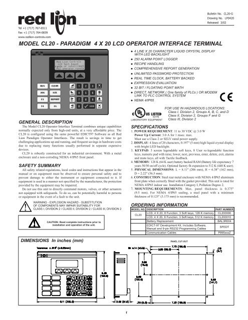
Tel +1 (717) 767-6511Fax +1 (717) 764-0839www.redlion-controls.comMODEL <strong>CL20</strong> - PARADIGM 4 X 20 LCD OPERATOR INTERFACE TERMINAL! 4 LINE X 20 CHARACTER LIQUID CRYSTAL DISPLAYWITH LED BACKLIGHT! 250 ALARM POINT LOGGER! RECIPE HANDLING! COMPREHENSIVE REPORT GENERATION! UNLIMITED PASSWORD PROTECTION! REAL TIME CLOCK, BATTERY BACKED! EXPRESSION EVALUATION! 32 BIT / FLOATING POINT MATH! DIRECT, NETWORK ( One family of PLCs ) OR MODEMLINK TO PLC CONTROL SYSTEM! NEMA 4/IP65Bulletin No. <strong>CL20</strong>-GDrawing No. LP0420Released 3/02GENERAL DESCRIPTIONThe Model <strong>CL20</strong> Operator Interface Terminal combines unique capabilitiesnormally expected only from high-end units, at a very affordable price. The<strong>CL20</strong> is configured using the same powerful EDICT97 Software as all <strong>Red</strong><strong>Lion</strong> Paradigm Operator Interfaces. The result is savings in time to getchallenging applications up and running, and frequent savings in hardware costsdue to replacing many functions usually performed in separate expensivedevices.<strong>CL20</strong> is robustly constructed for an industrial environment. With a metalenclosure and a non-corroding NEMA 4/IP65 front panel.SAFETY SUMMARYAll safety related regulations, local codes and instructions that appear in themanual or on equipment must be observed to ensure personal safety and toprevent damage to either the instrument or equipment connected to it. Ifequipment is used in a manner not specified by the manufacturer, the protectionprovided by the equipment may be impaired.Do not use this unit to directly command motors, valves, or other actuatorsnot equipped with safeguards. To do so, can be potentially harmful to personsor equipment in the event of a fault to the unit.WARNING - EXPLOSION HAZARD - SUBSTITUTIONOF COMPONENTS MAY IMPAIR SUITABILITY FORCLASS I, DIVISION 2 / CLASS II, DIVISION 2 / CLASS III, DIVISION 2CAUTION: Read complete instructions prior toinstallation and operation of the unit.DIMENSIONS In inches (mm)63YNLABORATORY EQUIPMENTSPECIFICATIONS1. POWER REQUIREMENT: 11 to 30 VDC @ 3.0 WPower Up Current: 3.0 A for 1 msec. max.Must use a Class 2 or SELV rated power supply.2. DISPLAY: 4 lines of 20 characters, 0.197" (5 mm) high liquid crystal displaywith bright LED backlight.3. KEYPAD: 3 screen legendable soft keys, 8 User re-legendable functionkeys, numeric pad with raise, lower, next, previous, enter, delete, exit, alarmsand mute keys, all with Tactile feedback.4. MEMORY: 128 K (64 K user) battery backed RAM (Battery life expectancy 7years 50/50 on/off cycle). Optional factory fit expansion to 512 K (448 K user).5. PHYSICAL DIMENSIONS: L = 8.11" (206 mm), H = 6.38" (162 mm),D = 2.22" (56.5 mm).6. CONSTRUCTION: Steel rear metal enclosure with NEMA 4/IP65 aluminumfront plate when correctly fitted with the gasket provided. This unit is rated forNEMA 4/IP65 indoor use. Installation Category I, Pollution Degree 2.7. MOUNTING REQUIREMENTS: Max. panel thickness is 0.375"(9.5 mm). For NEMA 4/IP65 sealing, a steel panel with a minimumthickness of 0.125" (3.175 mm) is recommended.ORDERING INFORMATIONFOR USE IN HAZARDOUS LOCATIONS:Class I, Division 2, Groups A, B, C, and DClass II, Division 2, Groups F and GClass III, Division 2MODEL NO. DESCRIPTIONPART NUMBER<strong>CL20</strong>LCD, 4 X 20, 8 Function, 3 Soft keys, 128 K memory <strong>CL20</strong>0000LCD, 4 X 20, 8 Function, 3 Soft keys, 512 K memory <strong>CL20</strong>0010Battery ReplacementBAL3R004EDICT-97 Development Kit. Includes Software,<strong>Manual</strong> and 9-pin RS232 Programming CablesSFEDTCommunication CablesP895xxxZPANEL CUT-OUT1
8. CERTIFICATIONS AND COMPLIANCES:SAFETYUL Recognized Component, File # E179259, UL3101-1, CSA 22.2 No. 1010-1Recognized to U.S. and Canadian requirements under the ComponentRecognition Program of Underwriters Laboratories, Inc.UL Listed, File # E211967, UL3101-1, UL1604, CSA 22.2 No. 1010.1,CSA 22.2 No. 213-M1987LISTED by Und. Lab. Inc. to U.S. and Canadian safety standardsType 4 Enclosure rating (Face only), UL50IECEE CB Scheme Test Certificate # UL2795-179259/USA,CB Scheme Test Report # 98ME60993-000098Issued by Underwriters Laboratories, Inc.IEC 1010-1, EN 61010-1: Safety requirements for electrical equipmentfor measurement, control, and laboratory use, Part 1.IP65 Enclosure rating (face only), IEC 529ELECTROMAGNETIC COMPATIBILITYImmunity to EN 50082-2Electrostatic discharge EN 61000-4-2 Level 2; 4 Kv contactLevel 3; 8 Kv airElectromagnetic RF fields EN 61000-4-3 Level 3; 10 V/m80 MHz - 1 GHzFast transients (burst)EN 61000-4-4 Level 4; 2 Kv I/OLevel 3; 2 Kv powerRF conducted interference EN 61000-4-6 Level 3; 10 V/rms 1150 KHz - 80 MHzEmissions to EN 50081-2RF interferenceEN 55011 Enclosure class B1. Self-recoverable loss of performance during EMI disturbance at 10 Vrms:Communications error may occur during EMI disturbance.For operation without loss of performance:I/O cables are routed in metal conduit connected to earth ground.COMMON FEATURES FOR CHARACTER BASED OPERATOR TERMINALSPROGRAMMABILITYEvent Driven Configuration ToolEdict 97, an extremely powerful Windows 95/3.11 based software program,provides for the intuitive configuration of every aspect of the operatorinterface’s behavior. The requirement for time consuming PLC ladder logic isdrastically reduced by the unique event driven approach of EDICT 97. Thecapability of this program, in conjunction with the PLC and the Paradigmoperator interface unit, ensures a great deal of advanced functionality for yoursystem. This powerful PLC/Paradigm system provides many of the capabilitiesand features normally associated with the more complicated and costlyPC/SCADA systems. Display pages are easily generated, including PLC andinternal variables, text strings, or bar charts. All dynamic elements are alsoavailable as alarms, recipes, triggers, and reports, for the run time software.After completion of the programming, the program is directly downloaded tothe operator interface from your PC, without any compiling or savingrequirement. When you require a change in your program, EDICT 97 loads onlythe change, not the entire program, saving valuable on-line time.DYNAMIC DISPLAY PAGE ELEMENTSEach display page has provisions to show static and dynamic information,including data variables, text messages, time, and date.<strong>Data</strong> Variables can be either PLC derived or internally generated, either in dataentry or display only mode. The Paradigm unit has an extremely powerfulmath capability, allowing the operator to manipulate the variables to meet thespecific application’s demands. If required, the display can be formatted toBCD, binary, hex, floating point, and string. Upper and lower limits of dataentry variables are fully supported and able to be password protected.Text Message Animation enables several different types of animated text froma local or global message table to be displayed. The message displayed isdependent on the condition of the particular controlling expression. Thecontrolling expression may be a PLC bit level, a timer value, preset countercondition, or any one of a wide variety of message triggers.Time and Date in the Paradigm unit has the capability to display in anycombination of year, month, day, hours, minutes, and seconds.Bar Graphs in horizontal format are easily attached to data variables. Thepartial or full length bar graph displays can be scaled and offset to optimizethe required display effect.SECURITYThe password protection scheme provides the ultimate in tamper-proofcapability. Access can be limited on a unit, page, recipe, or even individual dataentries.29. ENVIRONMENTAL CONDITIONS:Operating Temperature: 0 to 40°CStorage Temperature: -20 to 80°COperating and Storage Humidity: 80% max. relative humidity(non-condensing) from 0°C to 40°C.Altitude: Up to 2000 meters10. WEIGHT: 2.1 lb. (0.95 Kg)INPUT/OUTPUT COMMUNICATIONS SPECS1. SERIAL PORTS: <strong>Data</strong> Format and Baud Rates for each port is individuallysoftware programmable up to 19200 baud.Port 1: Programming Port - RS-232 on an RJ-11 jack.Port 2: RS-232 Port on a Plug-In Screw Terminal BlockPort 3: RS-485 Port on a Plug-In Screw Terminal Block(Up to 29 units can be connected and individually addressed.)Note: LED Indicators show communications status on Ports 2 & 32. COMMUNICATION MODES: Any of the three ports can be used tocommunicate with Serial Devices.Model - (<strong>CL20</strong>0000) only one of Ports 1, 2, and 3 may be configured.Exception <strong>Red</strong> <strong>Lion</strong> <strong>Controls</strong> Instrument, simple ASCII Printer, PC LinkNetwork, Program Through, External Keyboards, and Roll-Your-OwnProtocols can be used with other protocols on all Ports.Model - (<strong>CL20</strong>0010) may communicate in Master mode with a differentdevice protocol on each port (See Note & Exception).However, only one of the Ports 2 and 3 may be configured, if either isselected as a Slave Protocol.Note: Ports 2 and 3 may be configured as different device protocols inMaster mode and Port 1 may be used simultaneously in Slave mode fora third device protocol.Exception: If Allen Bradley DH485 is selected on either Port 2 or 3, onlyPort 1 will be available for a separate device protocol.ALARMSThe Paradigm unit can monitor and log from 100 to 500 alarms, dependingon model. Such triggers as a simple bit level transition, a PLC coil activation,or a complex application algorithm can activate an alarm. The alarms can betime and date stamped, with an automatic screen display and/or downloading toa printer for hard copy recording purposes.REAL TIME SCHEDULEReal time schedule allows for repetitive or one time task to take place in thesystem. Typically a schedule action similar to...At 1:55 PM on Monday,Wednesday, and Friday, print the production report...is required in theapplication. In conjunction with the recipe capabilities, a downloading of aspecial recipe can be requested by the real time schedule feature.USER PROGRAMSThis feature offers the user the ability to incorporate custom applicationrequirements via a powerful program language. For example, a programdesignated “Calculate Volume” which determines the amount of fluid in a roundtank at specific temperatures could be created. This program would be triggeredto run and display each time the page denoted as “Volume Now” is requested.The ability to customize to your application’s specialized needs is easilysolved with the user program capability.KEYBOARD EDITINGAll the interface keys can be programmed to perform virtually unlimitedfunctions with each key, having multiple actions assigned to three types of keyevents: key pressed, key held down (auto repeat), and key released. Typical keyactions would be Go to page, set value, load recipe, view alarms, print report,and many more.COMMUNICATIONSWith over 70 communication drivers available, the Paradigm operatorinterface offers a wide range of connectivity including: PLCs, Variable SpeedDrives, Temperature Controllers, Bar Code Readers, etc.Utilizing real PLC data references, the automatic comms configurationoptimizes the system’s communication performance. In the event that yourspecific driver does not appear on the Paradigm drivers list, let us know, as thislist is always being expanded to meet our customers’ needs.
HARDWARE INFORMATIONThis bulletin contains a variety of information related to the installation andoperation of the Operator Interface supplied. Ideally, you should read thisdocument thoroughly before attempting to use the equipment. For informationabout the software aspects of the terminal, please consult other documentation.CONTENTS OF PACKAGEThe Operator Interface is supplied in a packaging box containing thefollowing...! The interface terminal itself.! A NEMA 4/IP65 rated mounting gasket.! A bag containing panel hardware.! This hardware bulletin.! If any of these items are missing, please contact your supplierimmediately.ALL NONINCENDIVE CIRCUITS MUST BE WIRED USINGDIVISION 2 WIRING METHODS AS SPECIFIED IN ARTICLE501-4 (b), 502-4 (b), AND 503-3 (b) OF THE NATIONALELECTRICAL CODE, NFPA 70 FOR INSTALLATION WITHINTHE UNITED STATES, OR AS SPECIFIED INSECTION 19-152 OF CANADIAN ELECTRICAL CODE FORINSTALLATION IN CANADA.POWER SUPPLY REQUIREMENTSThe Operator Interface requires an 11 to 30 VDC power supply rated at 3 Wunless otherwise stated on the label.! The terminal may take as little as 100 mA in certain circumstances, sobe sure that the chosen power supply can operate correctly with thisload. Large switch-mode supplies tend to need a certain minimum loadbefore they will operate correctly.In any case, it is very important that the power supply is mounted correctly ifthe unit is to operate reliably. A very high proportion of reported problems arecaused by incorrect power supply installation, so please take care to observe thefollowing points...! The power supply must be mounted close to the unit, with usually notmore than 6 feet of cable between the supply and the Operator Interface.Ideally, as short a length as is possible should be used.! The wire used to connect the Operator Interface’s power supply shouldbe of at least 22 gauge wire. If a longer cable run is used, you shoulduse heavier gage wire. The routing of the cable should be kept awayfrom large contactors, inverters and other devices which may generatesignificant electrical noise.BATTERY BACKUP ISSUESThe Operator Interface is supplied with a Lithium Battery designed tomaintain the internal memory and real-time clock during power outages.Assuming the operator interface terminal is powered up for 50% of the time,this battery should last over 4 years. A “Battery Low” system variable isavailable so that the programmer can choose specific action(s) to occur whenthe battery voltage drops below its nominal voltage.It is possible to replace the battery without losing the contents of the OperatorInterface’s memory, but this does not reduce the importance of ensuring that acopy of the terminal’s configuration is kept readily at hand to allow the terminalto be re-loaded in the case of mishaps. Please remember that although an imageof the database contents can be uploaded, this file is not editable, so theimportance of keeping a copy on disk cannot be over stressed.! The battery is located in a holder on the main circuit board. This shouldbe clearly visible. Remove the battery from its holder.! Place the new battery in the holder. The terminal’s power supply cannow be disconnected, if you re-applied power in the step above.! Replace the lid, screws and connector by following the above procedurein reverse. You may like to make a note of the date the battery wasreplaced to allow planned maintenance to be carried out.! If you did not keep the unit powered-up during battery replacement, holddown the EXIT and MUTE keys on the keyboard and cycle power.Release the keys and follow the menu guides to to clear the internalmemory. The unit is now ready for a suitable configuration database tobe re-loaded.Please note that the old battery must be disposed of in a manner whichcomplies with your local waste regulations. Also, the battery must not bedisposed of in fire or in a manner whereby it may be damaged and its contentscome into contact with human skin.INSTALLATION & CONNECTIONSThe unit meets NEMA 4/IP65 requirements for indoor use, when properlyinstalled. The units are intended to be mounted into an enclosed panel.Installation EnvironmentThe unit should be installed in a location that does not exceed the maximumoperating temperature and provides good air circulation. Placing the unit neardevices that generate excessive heat should be avoided.Continuous exposure to direct sunlight may accelerate the aging process ofthe bezel. The bezel should be cleaned only with a soft cloth and neutral soapproduct. Do NOT use solvents.Do not use tools of any kind (screwdrivers, pens, pencils, etc.) to operate thekeypad of the unit.MOUNTING INSTRUCTIONSThe Operator Interfaces are designed for through-panel mounting. Aneoprene gasket is provided, to enable sealing to NEMA 4/IP65 specification.The panel cut-out diagram for the model supplied is provided. All mountingholes should be drilled for 0.14" (3.5 mm) clearance. Care should be taken toremove any loose material from the mounting hole to avoid such metal fallinginto the Operator Interface itself during installation.CONNECTING TO A PLCThe Operator Interface is designed to operate with a PLC. A serialcommunication connection must be made between the operator interfaceterminal and PLC, and the details of this connection vary according to whichPLC is used.The following section lists the connection details for the PLC to be used .PLC TYPEDetails on how to connect to most PLCs are available on request from RLC.CONNECTING TO AN IBM ® PC/ATThe Operator Interface is programmed via software running on an IBMPC/AT or a compatible computer. The connection between the PC/AT and theoperator interface terminal is made via a custom cable provided with the EDICTDeveloper’s Kit. The cable is designed for a 9-way serial port. Please contactyour supplier if you require a 25-way version.WARNING - EXPLOSION HAZARD - THE AREA MUST BEKNOWN TO BE NON-HAZARDOUS BEFORE SERVICING/REPLACING THE UNIT AND BEFORE INSTALLING ORREMOVING I/O WIRING AND BATTERY.WARNING - EXPLOSION HAZARD - DO NOT DISCONNECTEQUIPMENT UNLESS POWER HAS BEEN DISCONNECTEDAND THE AREA IS KNOWN TO BE NON-HAZARDOUS.CHANGING THE BATTERYTo change the internal battery, follow these steps...! Remove the power and PLC communications connector from the unit.! Remove the four screws from the rear-cover and remove the cover.! If you wish to avoid losing the terminal’s configuration, reconnect thepower connector and re-apply power. Note that this will require thepanel to be powered-up and, as such, only suitably qualified staff shouldcarry out this procedure.3
PROGRAMMING PORT PIN OUTThe Operator Interface’s programming port is sometimes used to connectother RS-232 devices, such as printers. The following illustration and tablegives the pin-out of this port to enable such connections to be made.Rear View of UnitThe above table denotes the pin names of the programming port. Whenconnecting, the pin name at the programming port is connected to the oppositeof that pin name at the destination device.FUNCTION KEY STRIPSThe function keys on the <strong>CL20</strong> have clear windows that permit the user toinsert labels appropriate to the process. A formatted page is supplied uponwhich the user can enter function names (e.g. RUN, PRINT, etc.). These stripsare inserted from the rear of the panel through slots below the function keyslocated underneath the gasket.Take care that the ink applied will not rub off of the paper, or else blemisheswill be left on the inside of the window. Laminated paper or plastic film canprove easier to insert than normal photocopier paper. It also helps if the startingedge of the paper has about 0.25 inches (6.4 mm) of its corners cut off at a 45degree angle.Note: Add an additional 1.5" to label length to allow for easier insertion andremoval.TROUBLESHOOTINGFor further technical assistance, contact technical support at the appropriatecompany numbers listed.© 2001, RED LION CONTROLS, ALL RIGHTS RESERVED.Information in this document is subject to change without notice and does not represent a commitment by <strong>Red</strong> <strong>Lion</strong><strong>Controls</strong>. Software, which includes any database supplied therewith, described in this document may be furnished subjectto a license agreement or a nondisclosure agreement. It is against the Law to copy the software except as specificallyallowed in the license or nondisclosure agreement. No part of this document may be reproduced in any form or by anymeans, electronic or mechanical, including photocopying and recording, for any purpose, without the express writtenpermission of <strong>Red</strong> <strong>Lion</strong> <strong>Controls</strong>.PowerPoint and Windows are registered trademarks of Microsoft Corporation. Other product and company namesmentioned herein may be the trademarks of their respective owners.Disclaimer<strong>Red</strong> <strong>Lion</strong> <strong>Controls</strong>, hereinafter referred to as RLC, will under no circumstances be responsible for direct, indirect,special, incidental or consequential damages, death or personal injury arising from the use or misuse of all or part of thisdocumentation or the products and software described herein. Notwithstanding the above, RLC does not exclude anyliability for death or personal injury caused by its negligence.RLC does not warrant any of its software products to be free from error or to be fit for any particular purpose. Neitheris the software guaranteed to provide operation without interruption. The customer's sole remedy in case of failure is therefund of the purchase price of the software.The customer, in applying the products and software described herein, accepts that the products are wholly or partlyprogrammable electronic systems that are inherently complex and which cannot thus be guaranteed to be free of errors. Indoing so, the customer accepts the responsibility to ensure that the products are correctly programmed, configured,installed, commissioned, operated and maintained by competent and suitably trained staff and according to any instructionsor safety instructions provided and as dictated by good engineering practices.This documentation, and the software and products described herein, is subject to continuous development andimprovement. All information is given in good faith, but RLC shall not be liable for any omissions or errors herein orwithin the software herein described.<strong>Red</strong> <strong>Lion</strong> <strong>Controls</strong>20 Willow Springs CircleYork PA 17402Tel +1 (717) 767-6511Fax +1 (717) 764-0839<strong>Red</strong> <strong>Lion</strong> <strong>Controls</strong> France56 Boulevard du Courcerin, Batiment 21,ZI Pariest F-77183 Croissy BeaubourgTel +33 (64) 80 12 12Fax +33 (64) 80 12 13<strong>Red</strong> <strong>Lion</strong> <strong>Controls</strong> BV<strong>Data</strong>bankweg 6CNL - 3821 AL AmersfoortTel +31 (33) 472 32 25Fax +31 (33) 489 37 93