Technical handbook for the paddy rice postharvest industry in ...
Technical handbook for the paddy rice postharvest industry in ...
Technical handbook for the paddy rice postharvest industry in ...

Create successful ePaper yourself
Turn your PDF publications into a flip-book with our unique Google optimized e-Paper software.
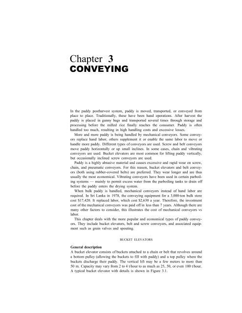
Chapter 3CONVEYINGIn <strong>the</strong> <strong>paddy</strong> <strong>postharvest</strong> system, <strong>paddy</strong> is moved, transported, or conveyed fromplace to place. Traditionally, <strong>the</strong>se have been hand operations. After harvest <strong>the</strong><strong>paddy</strong> is placed <strong>in</strong> gunny bags and transported several times through storage andprocess<strong>in</strong>g be<strong>for</strong>e <strong>the</strong> milled <strong>rice</strong> f<strong>in</strong>ally reaches <strong>the</strong> consumer. Paddy is oftenhandled too much, result<strong>in</strong>g <strong>in</strong> high handl<strong>in</strong>g costs and excessive losses.More and more <strong>paddy</strong> is be<strong>in</strong>g handled by mechanical conveyors. Some conveyorsreplace hand labor; o<strong>the</strong>rs supplement it or enable <strong>the</strong> same labor to move orhandle more <strong>paddy</strong>. Different types of conveyors are used. Screw and belt conveyorsmove <strong>paddy</strong> horizontally or up small <strong>in</strong>cl<strong>in</strong>es. In some cases, cha<strong>in</strong> and vibrat<strong>in</strong>gconveyors are used. Bucket elevators are most common <strong>for</strong> lift<strong>in</strong>g <strong>paddy</strong> vertically,but occasionally <strong>in</strong>cl<strong>in</strong>ed screw conveyors are used.Paddy is a highly abrasive material and causes excessive and rapid wear on screw,cha<strong>in</strong>, and pneumatic conveyors. For this reason, bucket elevators and belt conveyors(both us<strong>in</strong>g rubber-covered belts) are preferred. They wear longer and are thususually <strong>the</strong> most economical. Vibrat<strong>in</strong>g conveyors have been used <strong>in</strong> certa<strong>in</strong> parboil<strong>in</strong>gsystems — ma<strong>in</strong>ly to permit excess water from <strong>the</strong> parboil<strong>in</strong>g tanks to dra<strong>in</strong> offbe<strong>for</strong>e <strong>the</strong> <strong>paddy</strong> enters <strong>the</strong> dry<strong>in</strong>g system.When bulk <strong>paddy</strong> is handled, mechanical conveyors <strong>in</strong>stead of hand labor arerequired. In Sri Lanka <strong>in</strong> 1978, <strong>the</strong> convey<strong>in</strong>g equipment <strong>for</strong> a 3,000-ton bulk storecost $17,420. It replaced labor, which cost $2,630 a year. There<strong>for</strong>e, <strong>the</strong> <strong>in</strong>vestmentcost of <strong>the</strong> mechanical conveyors was paid off <strong>in</strong> less than 7 years. Although <strong>the</strong>re aremany o<strong>the</strong>r factors to consider, this illustrates <strong>the</strong> cost of mechanical conveyors vslabor.This chapter deals with <strong>the</strong> more popular and economical types of <strong>paddy</strong> conveyors.They <strong>in</strong>clude bucket elevators, belt and screw conveyors, and associated equipmentsuch as gra<strong>in</strong> valves and spout<strong>in</strong>g.BUCKET ELEVATORSGeneral descriptionA bucket elevator consists of buckets attached to a cha<strong>in</strong> or belt that revolves arounda bottom pulley (allow<strong>in</strong>g <strong>the</strong> buckets to fill with <strong>paddy</strong>) and a top pulley where <strong>the</strong>buckets discharge <strong>the</strong>ir <strong>paddy</strong>. The vertical lift may be a few meters to more than50 m. Capacity may vary from 2 to 4 t/hour to as much as 25, 50, or even 100 t/hour.A typical bucket elevator with details is shown <strong>in</strong> Figure 3.1.
3.1. Typical bucket elevator.46 POSTHARVEST INDUSTRY HANDBOOK
47 CONVEYINGTypesBucket elevators are available <strong>in</strong> several designs to handle many products. They areclassified accord<strong>in</strong>g to <strong>the</strong> type of discharge used and are identified as centrifugal,positive (gravity), and cont<strong>in</strong>uous (direct gravity). The three types are shown <strong>in</strong>Figure 3.2. The centrifugal discharge type is most commonly used with gra<strong>in</strong>s. It isdesigned and eng<strong>in</strong>eered to con<strong>for</strong>m with general practice <strong>in</strong> handl<strong>in</strong>g gra<strong>in</strong>. Headand boot shafts are provided with roller bear<strong>in</strong>gs. Takeups are generally screw-typeexcept on tall high-capacity units where gravity-type take-ups are more common.Buckets are usually made of steel or plastic and are bolted onto <strong>the</strong> belt. Cas<strong>in</strong>gs orlegs are also made of steel, are welded or bolted toge<strong>the</strong>r, and are dusttight. Thecurved hood is designed <strong>for</strong> proper centrifugal discharge of <strong>the</strong> <strong>paddy</strong> gra<strong>in</strong>. Theboot can be loaded from <strong>the</strong> front or back or both (Fig. 3.3). In larger, high-capacity<strong>in</strong>stallations <strong>the</strong> head section is often vented and connected to an aspiration system.3.2. Elevators discharg<strong>in</strong>g<strong>paddy</strong>: A, centrifugal; B,gravity; C, direct gravity.3.3. Load<strong>in</strong>g <strong>paddy</strong> <strong>in</strong>to<strong>the</strong> boot of an elevator.Bucket types and capacitiesBuckets are made of different materials and come <strong>in</strong> different shapes and sizes,depend<strong>in</strong>g on requirements. Figure 3.4 shows a typical bucket used with centrifugaldischarge elevators. The buckets are uni<strong>for</strong>m, smooth, and proportioned <strong>for</strong> fastfill<strong>in</strong>g and quick, clean discharge. Figure 3.5 shows <strong>the</strong> correct method of bolt<strong>in</strong>g <strong>the</strong>bucket to <strong>the</strong> belt.Dimensions and capacities of different buckets are given <strong>in</strong> Table 3.1. Thecarry<strong>in</strong>g capacity is based on <strong>the</strong> angle of repose of <strong>paddy</strong>, which is normally 36° (seel<strong>in</strong>e x - x <strong>in</strong> Fig. 3-4.) Because of <strong>the</strong> difficulty of load<strong>in</strong>g all buckets to 100% of ratedcapacity and <strong>the</strong> desirability of hav<strong>in</strong>g a small reserve capacity <strong>in</strong> <strong>the</strong> elevator,designers calculate carry<strong>in</strong>g capacity on <strong>the</strong> basis of buckets be<strong>in</strong>g filled to 85 to 90%of rated capacity.Bucket spac<strong>in</strong>g or <strong>the</strong> m<strong>in</strong>imum vertical spac<strong>in</strong>g between bolt holes of elevatorbuckets is also shown <strong>in</strong> Table 3.1. Buckets may be as far apart as <strong>the</strong> requiredcapacity permits. lnstall<strong>in</strong>g buckets closer than <strong>the</strong> m<strong>in</strong>imum will probably result <strong>in</strong>reduced carry<strong>in</strong>g capacity because <strong>the</strong>y will not fill properly at <strong>the</strong> recommended beltspeed.Elevator capacitiesThe bucket elevator's capacity <strong>in</strong> tons of <strong>paddy</strong> per hour depends on bucket size andspac<strong>in</strong>g and on belt speed. Speed is <strong>the</strong> first critical factor to consider. The speed of3.4. Bucket used <strong>for</strong> centrifugaldischarge elevator.(Courtesy of ScrewConveyor Corp.)
48 POSTHARVEST INDUSTRY HANDBOOK3.5. Correct method ofbolt<strong>in</strong>g <strong>the</strong> bucket to <strong>the</strong>belt.<strong>the</strong> belt <strong>in</strong> meters per m<strong>in</strong>ute depends on <strong>the</strong> head pulley speed. The recommendedhead pulley speed depends on <strong>the</strong> pulley diameter. A properly designed bucketelevator driven at <strong>the</strong> correct speed will make a clean discharge directly <strong>in</strong>to <strong>the</strong>throat of <strong>the</strong> head l<strong>in</strong>er ensur<strong>in</strong>g only slight <strong>paddy</strong> damage and little or no backlegg<strong>in</strong>gor downlegg<strong>in</strong>g. If <strong>the</strong> head pulley speed is too slow, <strong>the</strong> buckets spill <strong>the</strong><strong>paddy</strong> <strong>in</strong>to <strong>the</strong> legs. Paddy breakage occurs when <strong>the</strong> <strong>paddy</strong> is tumbled with<strong>in</strong> <strong>the</strong>pulley and re-elevated, as shown <strong>in</strong> Figure 3.6(A).The optimum speed is shown <strong>in</strong> Figure 3.6(B). The buckets fill and carry optimallyand discharge <strong>the</strong> <strong>paddy</strong> directly <strong>in</strong>to <strong>the</strong> throat — no spillage, no breakage.If <strong>the</strong> head pulley speed is too fast, <strong>paddy</strong> is damaged by rough and fast handl<strong>in</strong>gand <strong>the</strong> buckets will not fill properly. The buckets lose all <strong>the</strong>ir hold<strong>in</strong>g and dischargecontrol (Fig. 3.6(C)). The result is <strong>in</strong>efficient operation as well as excessive breakageand undue head wear of <strong>the</strong> elevator top.For optimum centrifugal discharge, <strong>the</strong> speed of <strong>the</strong> head pulley is calculated bywhere R is <strong>the</strong> radius of <strong>the</strong> wheel plus one-half <strong>the</strong> projection of <strong>the</strong> bucket <strong>in</strong>meters. Experience has shown that <strong>for</strong> <strong>paddy</strong> and most lightweight gra<strong>in</strong>s, a moreTable 3.1. Dimensions and capacities of elevator buckets.Bucket size Capacity (cm 3 )(mm)when filled tol<strong>in</strong>e x-xLength Projection Depth <strong>in</strong> Figure 3.4Normalspac<strong>in</strong>gon belt(mm)761021271521782032292542793053056470891021141271521521521521786476951141271401591591591591841422835668501416198231153398368139645380102102127152165178203203203203229
49 CONVEYING3.6. Elevator discharge atdifferent bucket speeds:A, too slow; B, optimum,C, too fast.satisfactory operational speed is 80 to 85% of <strong>the</strong> <strong>the</strong>oretical speed. Table 3.2 shows<strong>the</strong> recommended elevator speeds <strong>for</strong> different pulleys.Thus, elevator capacity may be calculated from 1) bucket capacity and recommendedspac<strong>in</strong>g found <strong>in</strong> Table 3.1, and 2) belt speed found <strong>in</strong> Table 3.2 as follows:Elevator capacity (m 3 /h) = (bucket capacity <strong>in</strong> m 3 /1,000,000) × (number ofbuckets per meter of belt) × (belt speed <strong>in</strong>meters/ m<strong>in</strong>ute) × (60 m<strong>in</strong>utes/ h);Table 3.2. Recommended elevator speeds <strong>for</strong> different size head pulleys.Pulley Average Head pulley rpmPulleycircum- bucketdiameterference projection Cal- Recom-(cm)(cm) (cm) culated mended30 94 10 6641 129 10 6051 160 10 5461 192 13 4976 239 15 4491 286 18 40122 383 20 36a Belt speed (m/m<strong>in</strong>) = (3.1416) × (pulley diameter <strong>in</strong> meters) × (recommended rpm).56514642313431Recommendedbeltspeed a(m/m<strong>in</strong>)536513808998119
50 POSTHARVEST INDUSTRY HANDBOOK<strong>the</strong>n us<strong>in</strong>g 576 kg/m 3 <strong>for</strong> <strong>paddy</strong> and one metric ton as 1,000 kg:Elevator capacity (t/h) = (elevator capacity <strong>in</strong> m 3 /h) × (576 kg/m 3 ) ÷(1,000 kg/t).For example, take a 0.41 m head pulley with 127 × 89 mm buckets on 127 mmspac<strong>in</strong>g:m 3 /h = (.00056 cm) 1000/127 (65 m/m<strong>in</strong>ute) (60) = 17.2 m 3 /ht/h = (17.2) (576) ÷ 1000 = 10Table 3.3 shows representative capacities <strong>for</strong> various head pulleys at variousrpm's.Elevator head sectionElevator heads should be of <strong>the</strong> proper shape and size with smooth contours. Figure3.7 illustrates many of <strong>the</strong> design features that should be considered. The dischargeside of <strong>the</strong> head should be shaped so that material thrown from <strong>the</strong> buckets will notbe deflected <strong>in</strong>to <strong>the</strong> downleg. The throat should be considerably below <strong>the</strong> headshaft to catch materials that are slow leav<strong>in</strong>g <strong>the</strong> buckets. Head section dimensions<strong>for</strong> different size head pulleys are shown <strong>in</strong> Figure 3.8.Lagg<strong>in</strong>g on <strong>the</strong> elevator head pulley (Fig. 3.9) is needed <strong>in</strong> pull<strong>in</strong>g heavy loads.Proper lagg<strong>in</strong>g <strong>in</strong>creases <strong>the</strong> coefficient of friction between <strong>the</strong> pulley and belt. Ontall legs a backstop device is recommended to prevent <strong>the</strong> belt from runn<strong>in</strong>gbackwards when elevator cups are loaded and power is cut off. A simple mechanicalrachet device serves well as a backstop.The strut board at a 45° angle under <strong>the</strong> head pulley (Fig. 3.8) prevents <strong>the</strong>accumulation of <strong>paddy</strong> and dust.The throat plate should be easily replaceable so that it can be changed after itwears out. The head shaft must be heavy enough to resist bend<strong>in</strong>g and to provide <strong>the</strong>required torque carry<strong>in</strong>g capacity. It must stay level and properly l<strong>in</strong>ed up. Antifrictionbear<strong>in</strong>gs, properly lubricated, are recommended.Table 3.3. Average capacities of certa<strong>in</strong> elevators with different speeds and bucket sizes.Head pulleyBucketCapacity (t/h) with head pulley speed ofdiameterSize Spac<strong>in</strong>g56 51 46 42 31 34(mm)(mm) (mm)mm mm mm mm rpm rpm30 89 × 64102 × 7041 102 × 70127 × 89152 × 10251 152 × 102178 × 114203 × 12761 203 × 127229 × 152254 × 15276 254 × 152279 × 152305 × 17891 305 × 178356 × 178122 356 × 178356 × 2031021021021271521521651781782032032032032292292292292542.65.2––––––––––––––––31rpm– – – – – –– – – – – –6.3 – – – – –10.0 – – – – –12.5 – – – – –– 14.2 – – – –– 21.8 – – – –– 28.3 – – – –– – 31.0 – – –– – 42.7 – – –– – 46.6 – – –– – – 51.3 – –– – – 55.6 – –– – – 72.2 – –– – – – 79.4 –– – – – 96.2 –– – – – – 117.2– – – – – 137.6
51 CONVEYING3.7. Elevator head show<strong>in</strong>gdesired features: A,spr<strong>in</strong>kler head and alarm;B, strut slanted to downleg; C, cleanout open<strong>in</strong>g;D, <strong>in</strong>spection door; E,lagged head pulley; F,buckets. Belt should be2.5 cm wider <strong>the</strong>n buckets,pulley should be 2cm wider than belt.3.8. Head section designdetails and dlmensions.Elevator boot sectionMost bucket elevators provide <strong>in</strong> <strong>the</strong> boot section a belt take-up device to tighten <strong>the</strong>belt as required and to tra<strong>in</strong> it so that it runs true and does not rub on ei<strong>the</strong>r side of<strong>the</strong> boot. A manual screw-type takeup is most often used (Fig. 3.10). On tall,heavy-capacity legs an automatic take-up boot pulley is used. This provides <strong>the</strong>correct belt tension at all times.The offset leg-type elevator shown <strong>in</strong> Figure 3.11 uses a boot pulley smaller than
52 POSTHARVEST INDUSTRY HANDBOOK3.9. Pulley lagg<strong>in</strong>g.3.10. Elevator boot sectionwith screw take-upadjustment.<strong>the</strong> head pulley, ma<strong>in</strong>ly to conserve space around <strong>the</strong> elevator boot. It should be nosmaller than two-thirds of <strong>the</strong> diameter of <strong>the</strong> head pulley.Gra<strong>in</strong> entry may be on ei<strong>the</strong>r side of <strong>the</strong> boot (Fig. 3.11). However, when gra<strong>in</strong>enters on <strong>the</strong> downleg, additional power is required <strong>for</strong> <strong>the</strong> “dredg<strong>in</strong>g effect” ofpull<strong>in</strong>g <strong>the</strong> buckets through <strong>the</strong> gra<strong>in</strong> <strong>in</strong> <strong>the</strong> boot.Cleanouts should always be <strong>in</strong>cluded on both sides of <strong>the</strong> boot to permit fast andeasy clean<strong>in</strong>g. They are usually placed at an angle (Fig. 3.10 and 3.11) and shouldslide easily.Elevator legsElevator legs are constructed as all welded, bolted, or riveted units. Cross sections ofdifferent types are shown <strong>in</strong> Figure 3.12. They are manufactured <strong>in</strong> standard lengthsof 2.4 m, but could be manufactured <strong>in</strong> any length desired. The economics of localmanufactur<strong>in</strong>g cost should determ<strong>in</strong>e which type of leg construction to use. Somemanufacturers f<strong>in</strong>d it more economical to employ s<strong>in</strong>glebox construction that<strong>in</strong>cludes both legs, as shown <strong>in</strong> Figure 3.13.Belts <strong>for</strong> bucket elevatorFour types of belts are used <strong>for</strong> bucket elevators and belt conveyors: 1) duck, 2)balata, 3) stitched canvas, and 4) solid woven cotton. Any of <strong>the</strong>se belts may betreated with special preparations or covered with natural or syn<strong>the</strong>tic rubber.
53 CONVEYING8.11. Boot section designdetails and dimensions.The standard cotton duck belt differs from ord<strong>in</strong>ary sail duck or canvas <strong>in</strong> that <strong>the</strong>strength of <strong>the</strong> warp (lengthwise threads) is considerably greater than that of <strong>the</strong> weft(crosswise threads). Duck <strong>for</strong> belts is ord<strong>in</strong>arily graded as 28 oz, 32 oz, etc.,accord<strong>in</strong>g to <strong>the</strong> weight of a piece 91 cm long <strong>in</strong> <strong>the</strong> warp and 107 cm wide.3.12. Cross don of differenttypes of elevatorlegs.Balata belts are made of waterproofed cotton duck belts held toge<strong>the</strong>r by balata, atree gum which is stronger than rubber at ord<strong>in</strong>ary temperature but not so elastic.Stitched canvas belts are multi-ply duck belts whose plies have been stitchedtoge<strong>the</strong>r and made waterproof. Solid woven belts are woven to thickness <strong>in</strong> loomsand are not of multiple construction. They are used primarily <strong>for</strong> powertransmission.Most conveyor and elevator belts are of folded-ply construction. Some belts aremade by build<strong>in</strong>g up layers of plies that are cut or woven to <strong>the</strong> width desired and arecalled "plied" construction belts. Table 3.4 shows m<strong>in</strong>imum plies used <strong>in</strong> elevators.The leverage on <strong>the</strong> bucket heads, due to <strong>the</strong> digg<strong>in</strong>g action and <strong>the</strong> load, <strong>in</strong>creaseswith greater bucket projections so that more plies are required to keep <strong>the</strong> bolts frompull<strong>in</strong>g through <strong>the</strong> belt.Belt selection also depends on pulley diameters. Table 3.5 shows maximum plies<strong>for</strong> standard pulley diameter.The type of belt splice depends on <strong>the</strong> thickness of <strong>the</strong> belt and <strong>the</strong> severity ofservice. For belts of five-ply thickness or less, <strong>the</strong> bolted clamp jo<strong>in</strong>t, <strong>the</strong> lap jo<strong>in</strong>t, or<strong>the</strong> buttstrap jo<strong>in</strong>t may be used (Fig. 3.14).For <strong>the</strong> clamp jo<strong>in</strong>t, belt ends must be bent outwards at right angles to <strong>for</strong>m aridge that is <strong>the</strong>n bolted between a bar clamp, On a lap jo<strong>in</strong>t splice, <strong>the</strong> lap extends adistance of three to five buckets and is secured by <strong>the</strong> same bolts that hold <strong>the</strong>buckets. (Use 20 mm bolts on four-ply belts, 25 mm <strong>for</strong> five- and six-ply, 32 mm <strong>for</strong>
54 POSTHARVEST INDUSTRY HANDBOOKTable 3.4. M<strong>in</strong>imum plies <strong>for</strong> bucket projectionsGra<strong>in</strong> M<strong>in</strong>imum plies when bucket projection is Beltelevator 8 cm 10 cm 13 cm 15 cm 18 cm 20 cm fabricLow-speed 4 4 5 5 6 6High-speed – – – 5 6 628 oz or 32 oz32 ozTable 3.5. Maximum belt plies vs diameter pulleys.Head pulley Maximum M<strong>in</strong>imum footdiam (cm) plies pulley diam (cm)516171769156789107 10122 12384653566676913.13. S<strong>in</strong>glebox type elevatorleg.seven- and eight-ply.) This splice is not suitable <strong>for</strong> belts more than seven plies thickbecause it is too stiff to pass tightly over <strong>the</strong> pulleys.The butt-strap jo<strong>in</strong>t may be used on belts of eight or more plies. Place one bolt <strong>for</strong>each 25 mm of belt width, 10 mm bolts <strong>for</strong> belts less than 10 plies, and 15 mm bolts<strong>for</strong> those more than 10 plies.Belt widths should be <strong>the</strong> bucket width, plus 25 mm. The pulley width should be<strong>the</strong> belt width, plus 25 mm or more.3.14. Splic<strong>in</strong>g elevatorbelts.AccessoriesFor servic<strong>in</strong>g <strong>the</strong> elevator head section, particularly <strong>the</strong> drive mechanism, a plat<strong>for</strong>m<strong>for</strong> work<strong>in</strong>g is needed. Access to this plat<strong>for</strong>m is usually by ladder equipped with asafety cage. A typical elevator with plat<strong>for</strong>m is shown <strong>in</strong> Figure 3.15. In some<strong>in</strong>stallations, jo<strong>in</strong>t or common ladders are used <strong>for</strong> two or more elevators or o<strong>the</strong>rmach<strong>in</strong>es.
55 CONVEYING3.15. Elevator with plat<strong>for</strong>m,ladder, and safetycage. (Courtesy of Card<strong>in</strong>alDivision, LMLCorp.)Power requirementsThe <strong>the</strong>oretical horsepower (hp) requirements <strong>for</strong> bucket elevators may be obta<strong>in</strong>edfrom <strong>the</strong> equation:where Q = capacity <strong>in</strong> kilograms per m<strong>in</strong>ute, H = lift <strong>in</strong> meters, and F = 1.5 <strong>for</strong>elevators loaded on <strong>the</strong> down side of <strong>the</strong> boot, 1.2 <strong>for</strong> elevators loaded on <strong>the</strong> up sideof <strong>the</strong> boot. Actual horsepower requirements are 10 to 15% higher than this<strong>the</strong>oretical value because of friction, power transmission, and drive losses. Forexample, horsepower requirements <strong>for</strong> a bucket elevator with 1,600 bu/h of <strong>paddy</strong>and a lift of 10.7 m loaded on <strong>the</strong> up side would be: (1,600 bu/h = 545 kg/m<strong>in</strong>ute)There<strong>for</strong>e <strong>the</strong> next larger standard size electric motor should be selected.
56 POSTHARVEST INDUSTRY HANDBOOKSCREW CONVEYORSGeneral <strong>in</strong>fomationFigure 3.16 shows a typical screw conveyor. It consists of a conveyor screw <strong>in</strong> atrough supported by end and hanger bear<strong>in</strong>gs. The screw rotation pushes <strong>the</strong> gra<strong>in</strong>along <strong>the</strong> trough. The pitch (distance from <strong>the</strong> center of one thread to <strong>the</strong> center of<strong>the</strong> next thread) of a standard conveyor screw is equal to its diameter. A 15-cmdiameter conveyor screw has a pitch of 15 cm. For each revolution of a standardscrew conveyor <strong>the</strong> <strong>paddy</strong> is advanced a distance equal to <strong>the</strong> pitch. The screwconveyor is used to move <strong>paddy</strong> horizontally. It can also be used at any angle up to90° from horizontal although <strong>the</strong>re will be a correspond<strong>in</strong>g reduction <strong>in</strong> capacity.The helicoid screw (Fig. 3.17A) is a cont<strong>in</strong>uous one-piece helix shaped from a flatstrip of steel and attached to a pipe or shaft. Its thickness decreases from <strong>the</strong> <strong>in</strong>neredge to <strong>the</strong> outer edge because of <strong>the</strong> strength necessary to <strong>for</strong>m <strong>the</strong> helix (Fig.3.17B). Smoothness of <strong>the</strong> helix is most important. Capacities and power require-3.16. Typical screw conveyor.3.17. Hellcoid conveyorscrew section.
57 CONVEYINGments vary with segmented or welded sections.Paddy is much more abrasive than most o<strong>the</strong>r gra<strong>in</strong>s and causes excessive wear on<strong>the</strong> flights as well as <strong>the</strong> trough. To reduce wear, flights (helicoid section m<strong>in</strong>us <strong>the</strong>shaft) may be fabricated from various materials such as sta<strong>in</strong>less steel, monel, orcopper alloys. But because <strong>the</strong>se materials are generally too expensive, a highcarbonsteel or o<strong>the</strong>r less expensive abrasive-resistant alloy is used.A number of o<strong>the</strong>r conveyor flights are designed <strong>for</strong> special purposes. The ribbonscrew conveyors convey sticky materials. Ano<strong>the</strong>r special type is a short-pitchconveyor — pitch may be one-half of screw diameter or less — generally used <strong>in</strong>feeders (Fig. 3.18). The short-pitch conveyor is used under a dump pit where fullload<strong>in</strong>g of <strong>the</strong> screw is expected.Screw conveyors may be designed <strong>for</strong> clockwise or counterclockwise rotationwithout change <strong>in</strong> capacity. The screw conveyor carries <strong>the</strong> material as seen <strong>in</strong> Figure3.19, on opposite sides (right-hand or left-hand). This characteristic may be considered<strong>in</strong> certa<strong>in</strong> <strong>in</strong>stallations, such as feed<strong>in</strong>g an elevator or mach<strong>in</strong>e.Sizes and capacitiesScrew conveyor components, <strong>in</strong> addition to <strong>the</strong> screw, <strong>in</strong>clude end bear<strong>in</strong>gs, hangerbear<strong>in</strong>gs, <strong>in</strong>let open<strong>in</strong>gs, and discharge open<strong>in</strong>gs (see Fig. 3.20 <strong>for</strong> details and generaldimensions). The dimensions of <strong>the</strong> helicoid screw are given <strong>in</strong> Figure 3.21.Paddy assumes a cross section load<strong>in</strong>g of 30% dur<strong>in</strong>g operation of a screwconveyor as shown <strong>in</strong> Figure 3.22. Based on this load<strong>in</strong>g factor, screw diameter, andrpm, <strong>the</strong> capacity <strong>for</strong> standard size screw conveyors is shown <strong>in</strong> Figure 3.22. Forscrew conveyors of standard construction, <strong>the</strong> capacity chart should always befollowed <strong>for</strong> recommended maximum speeds. Speeds selected below <strong>the</strong> maximumrecommended are conservative. Speeds above that should be referred to <strong>the</strong> manufacturerbe<strong>for</strong>e <strong>the</strong>y are used.From Figure 3.22 <strong>for</strong> example, a 15-cm conveyor at maximum speed of 120 rpmhas a capacity of 5.10 m 3 /hour. With <strong>paddy</strong> of 576 kg/m 3 , this is 2,937 kg or about3.0 t/ hour.(This is 39% of <strong>the</strong> <strong>the</strong>oretical calculated capacity based on <strong>the</strong> <strong>for</strong>mulaQ= (D 2 – d 2 )/ 36.6 × P × rpm, where Q is <strong>in</strong> ft 3 / hour, D = screw diameter <strong>in</strong> <strong>in</strong>ches,d = shaft diameter <strong>in</strong> <strong>in</strong>ches, and P = pitch <strong>in</strong> <strong>in</strong>ches. Because of screw hous<strong>in</strong>gclearance and <strong>the</strong> load<strong>in</strong>g factor, <strong>the</strong> actual capacity is less than <strong>the</strong> <strong>the</strong>oreticalcapacity.)3.18. Short pitch conveyor section.(top)3.19. Conveyor screw sections: A andB, right-hand; C and D, left-hand.(right)
58 POSTHARVEST INDUSTRY HANDBOOK3.20. Schematic and dimensions<strong>for</strong> screw conveyor.(top)3.21. Hellcoid flight conveyorscrew and dimensions(pitch = screwdiam). (bottom)3.22. Capacity of screwconveyors us<strong>in</strong>g helicoidsections. Capacity andpower requirements aredifferent <strong>for</strong> segmentedand welded sections.
59 CONVEYINGHorsepower requirements may be determ<strong>in</strong>ed by us<strong>in</strong>g <strong>the</strong> follow<strong>in</strong>g <strong>for</strong>mulas.The determ<strong>in</strong>ation does not consider power loss <strong>in</strong> drive equipment (belts, cha<strong>in</strong>s, orgear reducers), imperfect alignment, or <strong>the</strong> power required <strong>for</strong> start<strong>in</strong>g under load.Additional power is <strong>the</strong>re<strong>for</strong>e required <strong>for</strong> <strong>the</strong> average <strong>in</strong>stallation to overcome drivelosses and imperfect alignment.(DS + QK)(1) H= L1,000,000Where L = overall length <strong>in</strong> feetD = factor depend<strong>in</strong>g on typeof bear<strong>in</strong>gs (Table 3.6)S = speed <strong>in</strong> rpmQ = quantity of <strong>paddy</strong> <strong>in</strong>pounds per hourK = material factor, <strong>for</strong><strong>paddy</strong> = 0.4H×P(2) hp=0.85Where P = 2 when H is less than 1P = 1.5 when H is between 1and 2P = 1.25 when H is between 2and 4P = 1.1 when H is between 4and 5P = 1 when H is greater than5 and 0.85 is estimatedefficiency of <strong>the</strong> driveA sample problem:Determ<strong>in</strong>e conveyor size, speed, and horsepower requirements to move 20 t<strong>paddy</strong>/ hour over a distance of 24 m.Solution:From Figure 3.22 (20 t/ h × 1,000 kg/ t) ÷ 576 kg/ m 3 = 34.72 m 3 / h), a 30-cmscrew at 92 rpm would be adequate. Then, assum<strong>in</strong>g self-lubricat<strong>in</strong>g bronzebear<strong>in</strong>gs from Table 3.6, D = 96, H = (24 × 3.281) × (171 × 150 + 44,080 × 0.4) ÷1,000,000 = 3.41 <strong>the</strong>n:3.41 × 1.25hp = =5.010.85Table 3.6. “D” factors <strong>in</strong> comput<strong>in</strong>g horsepower <strong>for</strong> screw conveyors.Conveyordiam(cm)Ball orroller“D” factor <strong>for</strong> type of hanger bear<strong>in</strong>gsWood, babbitt,bronze ormoldedfabricSelflubricat<strong>in</strong>gbronzeWhiteiron ormanganesesteel7.5101523253035401012183238557810615213354669613518624335496114171255336355080130160250350480
60 POSTHARVEST INDUSTRY HANDBOOKThe next standard size electric motor above 5 hp should be used. The follow<strong>in</strong>gspecifications apply:Conveyor size: 30 cmConveyor speed: 92 rpmConveyor horsepower: 7.5Screw conveyors can be operated <strong>in</strong> an <strong>in</strong>cl<strong>in</strong>ed position with <strong>the</strong> flow of materialsupward. However, <strong>the</strong> allowable capacity rapidly decreases as <strong>the</strong> angle of <strong>in</strong>cl<strong>in</strong>ation<strong>in</strong>creases. A standard conveyor <strong>in</strong>cl<strong>in</strong>ed 15 degrees will carry about 75% of itsrated horizontal capacity. At an <strong>in</strong>cl<strong>in</strong>e of 25 degrees it will carry about 50% of itsrated horizontal capacity.The additional horsepower required over <strong>the</strong> horizontal horsepower requirementsis roughly 25% <strong>for</strong> a 15° <strong>in</strong>cl<strong>in</strong>ed conveyor and 50% <strong>for</strong> a 25° <strong>in</strong>cl<strong>in</strong>edconveyor. For a screw conveyor operated at an <strong>in</strong>cl<strong>in</strong>e greater than 25°, a tubularcas<strong>in</strong>g or a shrouded U trough should be used. It also becomes necessary at this angleto use shorter-than-standard pitch flights.Hangers and end bear<strong>in</strong>gsThe end thrust on a conveyor screw is aga<strong>in</strong>st <strong>the</strong> direction of material flow. An endthrust bear<strong>in</strong>g assembly absorbs this <strong>for</strong>ce and prevents excessive wear of <strong>the</strong>operat<strong>in</strong>g parts. A number of thrust arrangements are possible. One of <strong>the</strong> mostfrequently used is an outside-type thrust bear<strong>in</strong>g (Fig. 3.23). Preferably, <strong>the</strong> conveyordrive should be <strong>in</strong>stalled to drive through <strong>the</strong> end thrust because <strong>the</strong> shaft isfixed <strong>in</strong> position and cannot “float” <strong>in</strong> <strong>the</strong> end bear<strong>in</strong>g. However, <strong>the</strong> drive is often<strong>in</strong>stalled on <strong>the</strong> feed end of <strong>the</strong> conveyor because of space or o<strong>the</strong>r limitations.A standard-type hanger bear<strong>in</strong>g used <strong>for</strong> screw conveyors designed <strong>for</strong> <strong>paddy</strong> isillustrated <strong>in</strong> Figure 3.24. The 3.175 mm pipe tap provides a connection <strong>for</strong> a greasefitt<strong>in</strong>g and is most often used with a pressure-type grease cup. Additional life can beobta<strong>in</strong>ed by us<strong>in</strong>g ball bear<strong>in</strong>gs with dust seals <strong>in</strong> <strong>the</strong> hanger. Shields should beplaced on <strong>the</strong> upstream side of <strong>the</strong> bear<strong>in</strong>g to protect it from gra<strong>in</strong> pressure and wear.Inlets and discharge open<strong>in</strong>gsGenerally, <strong>in</strong>let open<strong>in</strong>gs may be cut <strong>in</strong>to <strong>the</strong> conveyor trough cover whereverneeded. Figure 3.20 shows <strong>in</strong>let spouts at two locations. Inlet open<strong>in</strong>gs should bekept at a sufficient distance from hanger bear<strong>in</strong>gs to prevent clogg<strong>in</strong>g or chok<strong>in</strong>g at3.23. Outside type thrustbear<strong>in</strong>g <strong>for</strong> heavy dutyservice.
61 CONVEYING3.24. Standard hangerbear<strong>in</strong>g.that po<strong>in</strong>t. For general use, <strong>the</strong> <strong>in</strong>let open<strong>in</strong>g is square and of <strong>the</strong> same dimensions as<strong>the</strong> <strong>in</strong>side width of <strong>the</strong> trough. The open<strong>in</strong>g may be flared or an <strong>in</strong>let spout may bedesigned to meet specific needs. Special side open<strong>in</strong>g <strong>in</strong>lets can also be designed tocontrol <strong>the</strong> depth of material fed to <strong>the</strong> trough at that po<strong>in</strong>t.Discharge spouts may be flared or made longer to meet special mach<strong>in</strong>ery needs.A standard open<strong>in</strong>g is square and equal to <strong>the</strong> <strong>in</strong>side width of <strong>the</strong> trough. Severaltypes of discharge open<strong>in</strong>gs and spouts are illustrated <strong>in</strong> Figure 3.25.3.25. Screw conveyor dischargeopen<strong>in</strong>gs andspouts.Troughs and coversA variety of screw conveyor troughs exist. Two types common to <strong>paddy</strong> requirementsare shown <strong>in</strong> Figure 3.26: <strong>the</strong> flanged type with flanged cover <strong>in</strong>stalled (A) and<strong>the</strong> angle flanged type without cover (B). Most troughs <strong>for</strong> handl<strong>in</strong>g <strong>paddy</strong> are madeof high carbon steel or abrasive-resistaat alloys to withstand <strong>the</strong> severe wear.O<strong>the</strong>r types of trough covers are illustrated <strong>in</strong> Figure 3.27. The flat cover is used<strong>in</strong>doors where waterproof<strong>in</strong>g is not necessary. For most outdoor conveyors where
62 POSTHARVEST INDUSTRY HANDBOOK3.26. Screw conveyortroughs. (top)3.27. Trough covers andclamps.waterproof<strong>in</strong>g is essential, <strong>the</strong> flanged-hip roof cover is used. Screw cover clamps aremost often used with both types of covers.Drive arrangementsBecause most screw conveyors are operated at relatively low speeds and electricmotors operate at relatively high speeds, a speed reducer is essential. Drives can bedirect coupled, or belt or cha<strong>in</strong> connected as shown <strong>in</strong> Figure 3.28.
63 CONVEYING3.28. Drive arrangements<strong>for</strong> screw conveyors: A,speed reducer mountedon conveyor shaft, motormounted with V belt connectionto slde or top; B,self-conta<strong>in</strong>ed unit withstandard speed reducermounted on <strong>the</strong> shaft,motor attached and drivenby V belt; C, gear motorwith built-<strong>in</strong> speed reducer,cha<strong>in</strong> drlve to screwshaft,3.29. Auger systems: A,portable; B, <strong>in</strong>stalled-<strong>in</strong>b<strong>in</strong>.Portable and b<strong>in</strong> augersThe previous section on screw conveyors provides design data on heavy-duty,cont<strong>in</strong>uous-operation screw conveyors, <strong>the</strong> type which would be used <strong>in</strong> a <strong>paddy</strong>storage-process<strong>in</strong>g plant.In many small storage <strong>in</strong>stallations, however, it may be necessary to load andunload b<strong>in</strong>s only a few times per year. This type of operation does not require <strong>the</strong>type of screw conveyors just described. A number of manufacturers produce specialscrew conveyors <strong>for</strong> occasional use. They are generally known as augers. Figure 3.29shows portable augers A used on an <strong>in</strong>cl<strong>in</strong>e to move <strong>paddy</strong> from a tractor-trailer <strong>in</strong>toa dryer and from <strong>the</strong> dryer <strong>in</strong>to a storage b<strong>in</strong>, and a horizontal unload<strong>in</strong>g auger Bunder <strong>the</strong> floor of a storage b<strong>in</strong> and a vertical auger to move <strong>paddy</strong> from <strong>the</strong> storageb<strong>in</strong> to a truck or <strong>in</strong>to a <strong>rice</strong> mill. These light-duty augers (fewer operat<strong>in</strong>g hours peryear) are housed <strong>in</strong> lightweight closed tubes <strong>in</strong>stead of an open U trough.Most often <strong>the</strong>y are operated at higher rpm’s than those recommended <strong>for</strong>heavy-duty screw conveyors shown <strong>in</strong> Figure 3.22. Thus <strong>the</strong>y achieve higher capacitiesthan small-diameter screw conveyors. Generally <strong>the</strong>se augers are less expensive
64 POSTHARVEST INDUSTRY HANDBOOK3.30. Horizontal augerwith details: A, augerhous<strong>in</strong>g, flight<strong>in</strong>g, andstubs; B, <strong>in</strong>termediateflight<strong>in</strong>g bear<strong>in</strong>gs; C, endplate with bear<strong>in</strong>g: D, reductionunit; E, drive unit.(Courtesy of GT Augers)3.31. Distribut<strong>in</strong>g and unload<strong>in</strong>gaugers.than heavy-duty types and are more attractive to <strong>the</strong> operator who does not requirecont<strong>in</strong>uous heavy-duty operation. An example of a horizontal auger with details ofits components is shown <strong>in</strong> Figure 3.30. This type could be used ei<strong>the</strong>r as anoverhead distribut<strong>in</strong>g auger or as a bottom unload<strong>in</strong>g auger (Fig. 3.31). Capacitiesand operat<strong>in</strong>g rpm's <strong>for</strong> different size augers are shown <strong>in</strong> Table 3.7.Table 3.7. Capacities of light-duty augers.Auger diam(cm)Capacity(m 3 /h)Operat<strong>in</strong>grpmM<strong>in</strong>imum hp requirements <strong>for</strong> augersmeasur<strong>in</strong>g8.5 m long 12.8 m long 18.6 m long15 35.4 450 3 520 42.5 218 5-7.5 7.520 70.8 370 – –25 84.9 205 – 10-152s 106.2 260 – –7.515–20–
65 CONVEYINGWhen <strong>the</strong> auger is operated <strong>in</strong> a vertical position, <strong>the</strong> capacity is greatly reduced.For example, when <strong>the</strong> 15-cm auger <strong>in</strong> Table 3.7 is operated vertically it has only 20m 3 /hour capacity at 620 rpm; <strong>the</strong> 20-cm auger, only 35.4 m 3 / hour capacity at 620rpm. Capacities vary with manufacturers.Portable augers are designed with <strong>the</strong> same type trough and screw flight constructionas <strong>the</strong> horizontal augers, but <strong>the</strong>y need extra outside re<strong>in</strong><strong>for</strong>cement because of<strong>the</strong>ir long lengths (Fig. 3.32). They are adjustable <strong>in</strong> height or angle to meet <strong>the</strong> needsof different size b<strong>in</strong>s or dryers. They may be powered by electric motors or gasol<strong>in</strong>eeng<strong>in</strong>es, or be driven by a tractor power takeoff. They are available <strong>in</strong> 15-cm, 20-cm,or 25-cm diameters. Their capacities vary considerably; <strong>for</strong> example, a 20-cm augeroperat<strong>in</strong>g at an angle of 20° may have a capacity of 70 m 3 / hour. But <strong>the</strong> same sizeauger operat<strong>in</strong>g at 45° may have a reduced capacity of only 50 m 3 / hour.M<strong>in</strong>imum electrical horsepower requirements could <strong>in</strong>crease by 1/3 with wet<strong>paddy</strong> if <strong>the</strong> same capacity <strong>in</strong> cubic meters per hour is ma<strong>in</strong>ta<strong>in</strong>ed.O<strong>the</strong>r portable augers are available <strong>in</strong> smaller diameters, <strong>in</strong> vary<strong>in</strong>g lengths, and<strong>for</strong> different operational needs.BELT CONVEYORSA belt conveyor (Fig. 3.33) is an endless belt operat<strong>in</strong>g between two pulleys with itsload supported on idlers. It may be flat <strong>for</strong> mov<strong>in</strong>g bags of <strong>paddy</strong>, or V-shaped <strong>for</strong>3.32. Portable auger.(Courtesy of GT Augers)3.33. Typical belt conveyor.
66 POSTHARVEST INDUSTRY HANDBOOKmov<strong>in</strong>g bulk <strong>paddy</strong>. The belt conveyor consists of a belt, drive and end pulleys,idlers, a drive and tension mechanism, and load<strong>in</strong>g and discharge devices. Itscarry<strong>in</strong>g capacity depends on <strong>the</strong> belt width, angle of trough, and belt speed.Belt conveyors have a high mechanical efficiency because <strong>the</strong> load is carried onantifriction bear<strong>in</strong>gs. Damage to <strong>paddy</strong> is virtually nil because <strong>the</strong>re is no relativemotion between <strong>the</strong> <strong>paddy</strong> gra<strong>in</strong>s and <strong>the</strong> belt. Carry<strong>in</strong>g capacity is high becauserelatively high speeds are possible. Paddy can be conveyed a long distance. Aproperly designed and ma<strong>in</strong>ta<strong>in</strong>ed belt system has long service life and low operat<strong>in</strong>gcost. The <strong>in</strong>itial cost is high <strong>for</strong> short distance belts and relatively low <strong>for</strong> longdistance belts compared to o<strong>the</strong>r types of horizontal conveyors. For <strong>the</strong>se reasons,belt conveyors are widely used to move <strong>paddy</strong> <strong>in</strong> many <strong>in</strong>stallations. They rangefrom 30-100 cm <strong>in</strong> width, and may be up to several hundred meters <strong>in</strong> length.The load cross section of a troughed belt is shown <strong>in</strong> Figure 3.34. Cross sectionareas of loaded belts of various sizes are given <strong>in</strong> Table 3.8. A trough angle of 20° isbest suited <strong>for</strong> <strong>paddy</strong> and most o<strong>the</strong>r gra<strong>in</strong>s. O<strong>the</strong>r common trough angles are 35°and 45°. Paddy <strong>for</strong>ms a surcharge angle ( A <strong>in</strong> Figure 3.34) of 20°. O<strong>the</strong>r commonsurcharge angles are 5° and 30°.Belt <strong>in</strong>cl<strong>in</strong>ation <strong>for</strong> <strong>paddy</strong> and most gra<strong>in</strong>s is limited to 15-17°. With <strong>in</strong>cl<strong>in</strong>eslarger than this, <strong>the</strong> gra<strong>in</strong> beg<strong>in</strong>s to roll or slide back down <strong>the</strong> belt thus reduc<strong>in</strong>g itseffective carry<strong>in</strong>g capacity.To determ<strong>in</strong>e <strong>the</strong> required belt width, <strong>the</strong> follow<strong>in</strong>g <strong>for</strong>mula is used with Table3.8:Capacity (bu/ h) = (area of cross section <strong>in</strong> m 2 ) × (speed<strong>in</strong> m/ m<strong>in</strong>ute) × (60) × (28.25)3.34. Cross section ofloaded belt: A is surchargeangle.Table 3.8. Cross-section area of loaded belt and maximum belt speeds.Belt width(cm)30.535.640.645.750.861.016.2Clear Total cross section Operation speed amarg<strong>in</strong> area (m 2 ) <strong>for</strong> 20° (mlm<strong>in</strong>)(cm) surcharge angle Normal Maximum4.14.34.64.85.15.66.4.0072.0089.0122.0161.0204.0308.0504616161767691107122122137137152183213a Belt speed should be 91 m/m<strong>in</strong> where a tripper is to be used, and 46-76 m/m<strong>in</strong>where a plow is to be used.
67 CONVEYINGExample: Determ<strong>in</strong>e belt width and speed to convey 1,200 bu of <strong>paddy</strong>/ hour. Us<strong>in</strong>g<strong>the</strong> cross sections from Table 3.8, a 35.6 cm belt travel<strong>in</strong>g at 81 m/ m<strong>in</strong>ute would give:.0089 × 81 × 60 × 28.25 = 1,221 bu/ hourand a 30.5 cm belt travel<strong>in</strong>g at 99 m/m<strong>in</strong>ute would give:.0072 × 99 × 60 × 28.25 = 1,208 bu/ hour.In this example <strong>the</strong> 35.6-cm-wide belt at 81 m/ m<strong>in</strong>ute is adequate, unless a tripper isto be used (m<strong>in</strong>imum of 91 m/m<strong>in</strong>ute <strong>for</strong> tripper use). Then <strong>the</strong> 30.5-cm belt at 99m/m<strong>in</strong>ute should be used.The top idler spac<strong>in</strong>g should be 1.5 m <strong>for</strong> belts up to 0.5 m wide and 1.4 m <strong>for</strong> belts0.6-0.9 m wide. The return idler spac<strong>in</strong>g <strong>for</strong> belts up to 0.9 m wide should not exceed3 m. After belt speed <strong>in</strong> meters per m<strong>in</strong>ute has been determ<strong>in</strong>ed, <strong>the</strong>n rpm of <strong>the</strong> headpulley shaft can be calculated with Table 3.9 as a guide.The horsepower required <strong>for</strong> mov<strong>in</strong>g <strong>paddy</strong> by belt conveyor may be calculatedby <strong>the</strong> follow<strong>in</strong>g <strong>for</strong>mulas that are based on <strong>the</strong> lift, friction resistance of <strong>the</strong> belt and<strong>the</strong> pulleys, and tripp<strong>in</strong>g device.Belt speed A + B (3.281 L )hp 1 =×0.3048100hp 2 = (t/ hour) ×0.48 + .01 L100liftt/ hourhp 3 = × 1.015 ×0.3048 l000Where L = belt length <strong>in</strong> meters, belt speed is <strong>in</strong> meters per m<strong>in</strong>ute, lift <strong>in</strong> meters, andA and B are constants from Table 3.10.Table 3.9. Revolutions per m<strong>in</strong>ute (rpm) of pulley shaft <strong>for</strong> various belt speedsand pulley diameters.Belt speedPulley shaft rpm when pulley diam is(m/m<strong>in</strong>)50 m 60 cm 76 cm 90 cm 110 cm3046611691107122202838485565751624324148556514202532384551111622273238439141824273236Table 3.10. Constants <strong>for</strong> determ<strong>in</strong><strong>in</strong>g horsepower <strong>for</strong> belt conveyors.Conveyor beltwidth (cm)AConstantsBAdditional hp<strong>for</strong> tripper3641465060760.20 .001400.25 .001400.30 .001620.30 .001870.36 .002240.48 .002980.700.851.001.401.702.50
68 POSTHARVEST INDUSTRY HANDBOOKThe total horsepower required is <strong>the</strong> sum of <strong>the</strong> powers calculated from <strong>the</strong> threeequations, plus that required <strong>for</strong> <strong>the</strong> tripper from Table 3.10.For example: A belt carry<strong>in</strong>g 18 t/hour, 41 cm wide, travel<strong>in</strong>g at 110 m/m<strong>in</strong>ute <strong>for</strong> adistance of 90 m, with a 3-m lift:110 0.25 + (.0014) (3.281) (90)hp 1 = ×= 2.390.3048 100.048 + (.10) (90)hp 2 = 18 ×100hp 3 =30.3048= 0.2518× 1.015 × = 0.181000Plus <strong>for</strong> <strong>the</strong> tripper (from Table 3.10) = 0.70Total hp = 3.523.35. Cross section of beltconveyor: A, drive pulley;B, idler; C, tripper, D, feedhopper; E, adjustable belttension<strong>in</strong>gpulley. (below)3.36. Belt load<strong>in</strong>g arrangementshow<strong>in</strong>g metal orwood frame with rubberskirt and extra set ofidlers. (bottom)A cross section of a belt conveyor with its major parts is shown <strong>in</strong> Figure 3.35.Note that <strong>the</strong> feed hopper is <strong>in</strong>stalled near <strong>the</strong> upper end of <strong>the</strong> belt. It has guides on<strong>the</strong> side to prevent <strong>the</strong> <strong>paddy</strong> from splash<strong>in</strong>g off as it feeds onto <strong>the</strong> belt. These guidesmay be metal or wood, 60-90 cm long, <strong>in</strong>stalled slightly above <strong>the</strong> belt surface toprevent wear on <strong>the</strong> belt. Details are shown <strong>in</strong> Figure 3.36.In Figure 3.35, <strong>the</strong> belt moves along <strong>the</strong> top idlers, which are spaced close toge<strong>the</strong>rto carry <strong>the</strong> load. The tail pulley is adjustable to ma<strong>in</strong>ta<strong>in</strong> <strong>the</strong> correct belt tension.Paddy is discharged by a belt tripper, which is movable along <strong>the</strong> length of <strong>the</strong> beltand <strong>in</strong>corporates a two-way discharge valve so that <strong>the</strong> <strong>paddy</strong> can be discharged on
69 CONVEYINGei<strong>the</strong>r side of <strong>the</strong> belt.A standard set of top idlers is shown <strong>in</strong> Figure 3.37. The side idlers are positionedat <strong>the</strong> 20° angle required <strong>for</strong> <strong>paddy</strong>. They are designed <strong>for</strong> periodic lubrication. Thecenter roller has an extended grease pipe on <strong>the</strong> side <strong>for</strong> easy access. Figure 3.38shows dimensions of standard idlers. Tapered roller bear<strong>in</strong>gs with outer dust andwater seals are most commonly used.Self-align<strong>in</strong>g idlers (Fig. 3.39) are used <strong>for</strong> tra<strong>in</strong><strong>in</strong>g troughed belts. They automaticallycorrect belt misalignment due to off-center load<strong>in</strong>g, uneven belt stretch,misalignment of supports, or o<strong>the</strong>r common field work<strong>in</strong>g conditions. A selfalign<strong>in</strong>gidler replaces a standard idler every 15-30 m.Self-align<strong>in</strong>g idlers should use <strong>the</strong> same rollers and bear<strong>in</strong>gs as <strong>the</strong> standard idlers.Self-align<strong>in</strong>g camber idlers (Fig. 3.40) <strong>in</strong>stalled on <strong>the</strong> return belt help tra<strong>in</strong> <strong>the</strong>loaded belt. The idlers are often overlooked <strong>in</strong> conveyor belt designs.Paddy generally is discharged from <strong>the</strong> belt conveyor over <strong>the</strong> end pulley or at anypo<strong>in</strong>t along <strong>the</strong> conveyor by a scraper plow or a throw-off carriage known as atripper. The discharge over <strong>the</strong> end pulley of <strong>the</strong> belt is simple and does not requireany special mechanism. A common use of this type discharge is from a belt conveyor<strong>in</strong>to <strong>the</strong> boot of a bucket elevator.The discharge scraper plow is a board placed at an angle (usually 30 to 49°) to <strong>the</strong>longitud<strong>in</strong>al axis of <strong>the</strong> belt and fastened on a frame that can be raised or loweredonto <strong>the</strong> belt as required. In <strong>the</strong> operat<strong>in</strong>g position, <strong>the</strong> plow rests on <strong>the</strong> belt,press<strong>in</strong>g aga<strong>in</strong>st it with a rubber strip fastened to <strong>the</strong> board. The plow can be used todischarge <strong>paddy</strong> from ei<strong>the</strong>r side of <strong>the</strong> belt. As <strong>the</strong> <strong>paddy</strong> gra<strong>in</strong>s travel<strong>in</strong>g on <strong>the</strong> beltcome <strong>in</strong> contact with <strong>the</strong> plow, <strong>the</strong>y are deflected to <strong>the</strong> side of <strong>the</strong> belt anddischarged. The discharge plow is not commonly used with <strong>paddy</strong> because small<strong>paddy</strong> gra<strong>in</strong>s often slide under <strong>the</strong> plow and are not discharged at <strong>the</strong> desired3.37. Standard idlers <strong>for</strong>belt conveyors. (Courtesyof Cont<strong>in</strong>ental ConveyorCorp.)
70 POSTHARVEST INDUSTRY HANDBOOK3.38. Dimensions of standardidlers us<strong>in</strong>g 12.7 emcenter rollers.3.39. Self-align<strong>in</strong>g idlers.(Courtesy of Cont<strong>in</strong>entalConveyor Corp.)location. Also, some gra<strong>in</strong>s are crushed or cracked between <strong>the</strong> plow and <strong>the</strong> beltsurface. If <strong>the</strong> plow is adjusted too close to <strong>the</strong> belt, excess belt wear results.Trippers are available as hand-propelled, self-propelled, or automatic. The choicedepends on <strong>the</strong> particular <strong>in</strong>stallation, its capacity, and system operation. A simplelight-duty hand-propelled tripper and its dimensions are shown <strong>in</strong> Figure 3.41. Note<strong>the</strong> direction of belt travel. As <strong>the</strong> belt passes over <strong>the</strong> top pulley, <strong>the</strong> <strong>paddy</strong> isdischarged immediately and spouted to <strong>the</strong> left or right as desired. The hand crank
71 CONVEYING3.40. Self-align<strong>in</strong>g camberreturn idlers. (Courtesyof Cont<strong>in</strong>ental ConveyorCorp.)3.41. Schematic and dimensionsof light-duty,hand-propelled tripper<strong>for</strong> various belt widths.(Courtesy of Cont<strong>in</strong>entalConveyor Corp.)with cha<strong>in</strong> drive on <strong>the</strong> side permits <strong>the</strong> operator to move <strong>the</strong> tripper <strong>in</strong> ei<strong>the</strong>rdirection along <strong>the</strong> belt. A tripper normally is <strong>in</strong>stalled on two I-beams runn<strong>in</strong>g <strong>the</strong>length of <strong>the</strong> belt conveyor and becomes part of <strong>the</strong> conveyor's frame.Note <strong>the</strong> two-way flip-flop valve <strong>in</strong> Figure 3.41, which permits <strong>the</strong> gra<strong>in</strong> to bedischarged on ei<strong>the</strong>r side of <strong>the</strong> belt as desired. This is a simple arrangement used <strong>in</strong>
72 POSTHARVEST INDUSTRY HANDBOOK3.42. Vertical automaticgravity belt tensioner.(below)3.43. Rubber lagged pulley.(right)most <strong>in</strong>stallations.The tripper also has a lock<strong>in</strong>g device that keeps it from mov<strong>in</strong>g when <strong>the</strong> belt iscarry<strong>in</strong>g <strong>paddy</strong>. The device is usually a vertical p<strong>in</strong>, dropped through a fixed open<strong>in</strong>gto keep <strong>the</strong> tripper <strong>in</strong> <strong>the</strong> locked position dur<strong>in</strong>g operation.For heavy-duty <strong>in</strong>stallations and when <strong>the</strong> tripper is to be moved often, aself-propelled or automatic tripper is often preferred. The self-popelled tripper<strong>in</strong>volves an extra set of pulleys which are used to drive <strong>the</strong> tripper.Automatic gravity take-ups are recommended <strong>for</strong> <strong>the</strong> longer belt conveyors toproperly ma<strong>in</strong>ta<strong>in</strong> <strong>the</strong> required driv<strong>in</strong>g tension at <strong>the</strong> head pulley. Where <strong>the</strong> propertension has been obta<strong>in</strong>ed by this type of take-up, it will be ma<strong>in</strong>ta<strong>in</strong>ed <strong>for</strong> <strong>the</strong> life of<strong>the</strong> belt, <strong>in</strong>dependent of operat<strong>in</strong>g conditions. Figure 3.42 shows a vertical unit. Thetake-up frame slides up and down on pipe guides. The m<strong>in</strong>imum take-up pulleydiameter <strong>in</strong> <strong>in</strong>ches equals four times <strong>the</strong> number of belt plies. M<strong>in</strong>imum bend pulleydiameter <strong>in</strong> <strong>in</strong>ches equals three times <strong>the</strong> number of belt plies.Figure 3.35 shows a horizontal, adjustable tail pulley <strong>for</strong> belt tension adjustment.This may be a simple screw adjustment <strong>for</strong> short, low-capacity conveyors (<strong>the</strong> sametype used <strong>for</strong> belt tension <strong>in</strong> bucket elevators <strong>in</strong> Fig. 3.11). Or it may be similar to that<strong>in</strong> Figure 3.42, where <strong>the</strong> weight is suspended over a set of pulleys <strong>for</strong> gravity control.Pulleys with rubber lagg<strong>in</strong>g are recommended when additional traction betweenbelt and pulley is required and when pulleys are operated under wet conditions.Lagg<strong>in</strong>g may be vulcanized to <strong>the</strong> pulley (Fig. 3.43) or bolted on (Fig. 3.9). W<strong>in</strong>gtypepulleys are usually heavy-duty, all-welded construction. The slop<strong>in</strong>g w<strong>in</strong>g platesautomatically shed <strong>the</strong> material to each side of <strong>the</strong> pulley to prevent buildup on <strong>the</strong>pulley face, which can cause considerable damage to <strong>the</strong> belt. Welded steel w<strong>in</strong>gpulleys (Fig. 3.44) are recommended <strong>for</strong> tail shafts of belt conveyors and boot shaftsof bucket elevators. For pulleys with diameter of 30-34 cm, 9 w<strong>in</strong>gs are provided;40-cm pulleys have 10 w<strong>in</strong>gs; 44-60 cm have 12 w<strong>in</strong>gs; and 66-91 cm have 16 w<strong>in</strong>gs.Belt conveyor drives can be of several designs; <strong>the</strong> choice depends on <strong>the</strong> economyof available materials. The most common are <strong>the</strong> gear motor type directly connectedor connected with a cha<strong>in</strong> drive. V-belts are used from motor to a countershaft orconnected with a cha<strong>in</strong> drive. V-belts are also used from motor to a directlyconnected speed reducer (Fig. 3.45).
73 CONVEYING3.44. W<strong>in</strong>g-type pulley.3.45. Belt conveyor drivesA, simple cha<strong>in</strong> drive frompower source; B, directgear motor; C, gear motorwith cha<strong>in</strong> reduction toshaft; D, V-belt drive tocountershaft with gear tohead shaft; E, V-belt tospeed reducer (directconnected); F, motor tospeed reducer coupled tohead shaft.OTHER PADDY CONVEYORSSeveral o<strong>the</strong>r type conveyors are occasionally used to move <strong>paddy</strong>. They <strong>in</strong>cludeshaker (vibrat<strong>in</strong>g), cha<strong>in</strong> (drag), and pneumatic conveyors. The major disadvantageof <strong>the</strong> shaker conveyor is its limited capacity. The major disadvantage of cha<strong>in</strong> andpneumatic conveyors is <strong>the</strong>ir short life due to <strong>the</strong> extreme abrasiveness of <strong>paddy</strong>
74 POSTHARVEST INDUSTRY HANDBOOKcompared to o<strong>the</strong>r gra<strong>in</strong>s. Because <strong>the</strong>se conveyors are seldom used <strong>for</strong> mov<strong>in</strong>g<strong>paddy</strong>, <strong>the</strong>ir discussion is limited.Shaker conveyorShaker (also called vibrat<strong>in</strong>g, oscillat<strong>in</strong>g, or grasshopper) conveyors move <strong>paddy</strong> <strong>in</strong>a uni<strong>for</strong>m, cont<strong>in</strong>uous flow by <strong>the</strong> upward and <strong>for</strong>ward oscillat<strong>in</strong>g motion of acont<strong>in</strong>uous trough that is mounted on sturdy <strong>in</strong>cl<strong>in</strong>ed reactor legs (Fig. 3.46). Theconveyor consists of a steel or wood trough mounted on flat spr<strong>in</strong>g, resilient supportlegs with a positive action drive. The drive consists of a motor turn<strong>in</strong>g a shaft onwhich an eccentric provides <strong>the</strong> oscillat<strong>in</strong>g action to <strong>the</strong> trough.The shaker conveyor is designed <strong>for</strong> horizontal convey<strong>in</strong>g. It is particularly suited<strong>for</strong> mov<strong>in</strong>g wet <strong>paddy</strong> from <strong>the</strong> parboil<strong>in</strong>g tanks to <strong>the</strong> dryer. In this case, <strong>the</strong> bottomof <strong>the</strong> trough is per<strong>for</strong>ated to permit excess water from <strong>the</strong> parboiled <strong>paddy</strong> to dra<strong>in</strong>be<strong>for</strong>e reach<strong>in</strong>g <strong>the</strong> elevator leg.The carry<strong>in</strong>g capacity of <strong>the</strong> shaker is small. A trough 30 cm wide by 10 cm deepwould be limited to about 5 t/ hour. A 46- × 10-cm trough would have a capacity ofabout 7.5 t/ hour. Horsepower requirements are low. A 5-t/ hour shaker conveyorwould be limited to a maximum length of 21 m and would require 1 hp.Cha<strong>in</strong> conveyorCha<strong>in</strong> conveyors are <strong>in</strong>expensive, slow, noisy, and mechanically <strong>in</strong>efficient. To move<strong>paddy</strong>, scrapers or drags used with <strong>the</strong> cha<strong>in</strong> operat<strong>in</strong>g <strong>in</strong> a closed conta<strong>in</strong>er ortrough <strong>in</strong>cur excessive wear due to <strong>the</strong> abrasive <strong>paddy</strong>. Figure 3.47 shows <strong>the</strong> crosssection of <strong>the</strong> conveyor trough and <strong>the</strong> normal movement of <strong>paddy</strong> as it is draggedby <strong>the</strong> conveyor cha<strong>in</strong>. Horsepower requirements <strong>for</strong> cha<strong>in</strong> conveyors are more than<strong>for</strong> belt or shaker conveyors of <strong>the</strong> same capacity. Because of <strong>the</strong> highly abrasivenature of <strong>paddy</strong>, <strong>the</strong> expected life of <strong>the</strong> cha<strong>in</strong> conveyor is considerably less than thatof <strong>the</strong> belt conveyor.3.46. Shaker or vibrat<strong>in</strong>gtypeconveyor show<strong>in</strong>gspr<strong>in</strong>g mount<strong>in</strong>g andpower drive.
75 CONVEYING3.47. Cross section ofcha<strong>in</strong>-drag conveyor.Pneumatic conveyorPneumatic conveyors move material <strong>in</strong> a closed-duct system by a high-velocity airstream. The system uses a material feeder or collector, an air blower, ducts, and acyclone <strong>for</strong> collection or discharge. Figure 3.48 illustrates a common use of <strong>the</strong>pneumatic system — unload<strong>in</strong>g ships or railcars and convey<strong>in</strong>g <strong>the</strong> gra<strong>in</strong> <strong>in</strong>to astorage or ano<strong>the</strong>r handl<strong>in</strong>g system.The power requirements <strong>for</strong> a pneumatic conveyor are high. A larger problem is<strong>the</strong> excessive wear on <strong>the</strong> equipment caused by <strong>the</strong> highly abrasive <strong>paddy</strong>. There<strong>for</strong>e,<strong>the</strong> pneumatic system is seldom used <strong>for</strong> mov<strong>in</strong>g <strong>paddy</strong>.The pneumatic convey<strong>in</strong>g system is most useful <strong>in</strong> handl<strong>in</strong>g less dense <strong>paddy</strong> huskand o<strong>the</strong>r by-products such as bran and f<strong>in</strong>e brokens. It is hard to beat <strong>for</strong> handl<strong>in</strong>ghusk and bran. Wear is m<strong>in</strong>imized by <strong>the</strong> proper duct design, velocity considerations(not too fast, not too slow), and match<strong>in</strong>g <strong>the</strong> system to <strong>the</strong> requirements.3.48. Typical pneumaticconvey<strong>in</strong>g system.
76 POSTHARVEST INDUSTRY HANDBOOKPortable conveyorAno<strong>the</strong>r type of portable loader or <strong>in</strong>cl<strong>in</strong>ed elevator is shown <strong>in</strong> Figure 3.49. It ischa<strong>in</strong> driven with paddles attached to <strong>the</strong> cha<strong>in</strong>, which operates <strong>in</strong> a metal trough. Itis used to move bulk <strong>paddy</strong> and gunny bags of <strong>paddy</strong> to higher sites. It may be 9-21 mlong and is most useful as a supplement to labor <strong>in</strong> stack<strong>in</strong>g bags of <strong>paddy</strong> <strong>in</strong> largestorage facilities.GRAIN VALVES AND SPOUTING3.49. Portable conveyor.(Courtesy of Card<strong>in</strong>alDivision, LML Corp.)In most <strong>paddy</strong>-handl<strong>in</strong>g <strong>in</strong>stallations, gra<strong>in</strong> valves and gra<strong>in</strong> spout<strong>in</strong>g are used withbucket elevators and screw conveyors. Paddy moves by gravity through <strong>the</strong>se gra<strong>in</strong>valves and spout<strong>in</strong>g. Because <strong>the</strong> angle of repose <strong>for</strong> <strong>paddy</strong> is 36-37° all spout<strong>in</strong>g is<strong>in</strong>stalled at a m<strong>in</strong>imum angle of 45°. Discharge valves are designed <strong>for</strong> this m<strong>in</strong>imumangle and as long as that angle is ma<strong>in</strong>ta<strong>in</strong>ed, <strong>paddy</strong> should flow freely.
77 CONVEYINGMost spout<strong>in</strong>g is straight steel pipe with flanged or unflanged ends, depend<strong>in</strong>g on<strong>in</strong>stallation requirements. Spout<strong>in</strong>g 15 cm <strong>in</strong> diameter is usually available <strong>in</strong> 14 or 12ga; 20 cm is available <strong>in</strong> 10, 12, or 14 ga. Standard 22.5°, 45°, and 60° elbows areavailable. Adjustable elbows that make <strong>in</strong>stallation much easier are also available.For capacities of 1,500 bu/hour (30 t/hour) or less, 15-cm spout<strong>in</strong>g and valves areadequate. For capacities from 1,500 to 3,000 bu/hour (60 t), 20-cm spout<strong>in</strong>g is used.From 3,000 bu to 4,500 bu/hour (90 t), 25-cm spout<strong>in</strong>g is used.The impact of fall<strong>in</strong>g <strong>paddy</strong> is extremely abrasive and rapidly wears out spout<strong>in</strong>gand elbows. A gra<strong>in</strong> trap such as that shown <strong>in</strong> Figure 3.50 is used where fall<strong>in</strong>g<strong>paddy</strong> would cause excessive wear on <strong>the</strong> elbow. The abrasive action of <strong>the</strong> <strong>paddy</strong> isabsorbed by <strong>the</strong> trapped gra<strong>in</strong> and saves wear on <strong>the</strong> elbow.3.50. Gra<strong>in</strong> trap used toreduce wear on elbows.3.51. Two-way valve withbucket-type gate.
78 POSTHARVEST INDUSTRY HANDBOOKTwo- and three-way gra<strong>in</strong> valves are <strong>the</strong> most common. They operate on ei<strong>the</strong>r<strong>the</strong> bucket-type gate as shown <strong>in</strong> Figure 3.51 or <strong>the</strong> flop gate as shown <strong>in</strong> Figure 3.52.Spr<strong>in</strong>g tension enables <strong>the</strong> valve to open <strong>in</strong> ei<strong>the</strong>r direction, The <strong>in</strong>ternal gate isfabricated of abrasive-resistant steel. The valve may be operated by cha<strong>in</strong> or cable.Normal dimensions <strong>for</strong> <strong>the</strong>se valves are given below:Valve dimensions (cm)A B C D E15-cm20-cmspout<strong>in</strong>gspout<strong>in</strong>g21.626.715.220.338.145.731.736.850.857.225-cm spout<strong>in</strong>g 31.825.454.640.661.0Two- and three-way valves are also available with round <strong>in</strong>lets and outlets. Theycome <strong>in</strong> different styles (Fig. 3.53) depend<strong>in</strong>g on <strong>the</strong> <strong>in</strong>stallation requirements. Thesame general dimensions given <strong>for</strong> gates with square <strong>in</strong>lets and outlets apply.Many <strong>in</strong>stallations require multiple distribution valves. An elevator <strong>in</strong> a dry<strong>in</strong>gsystem may be connected to six temper<strong>in</strong>g b<strong>in</strong>s and one dryer. For more than threeoutlets, distributors are used. Typical distributors are shown <strong>in</strong> Figure 3.54. Notethat <strong>the</strong> <strong>in</strong>side of each turns to make connections with <strong>the</strong> desired open<strong>in</strong>g or spout.Distributors can be made with many spouts and usually conta<strong>in</strong> one spout as anoverflow. Dimensions of a typical distributor are shown <strong>in</strong> Figure 3.55.3.52 Three-way valve withflop gate. (top)3.53. Two-way and threewayvalve arrangements.(right)
79 CONVEYING3.54. Five-way distributor.(top)3.55. Schematic and dimensions<strong>for</strong> two sizes ofdistributors. (upper right)3.56. Schematic of elevator.A, total height; B,head clearance; C, normallyquoted effective elevat<strong>in</strong>gheight; D, headloss due to distributor orvalves; E, effective elevat<strong>in</strong>gheight with distributor;F, hopper height upleg feed; G, hopper heightdown leg feed. (lowerright)
80 POSTHARVEST INDUSTRY HANDBOOKThe distributor is controlled by ei<strong>the</strong>r cable or steel rod from an <strong>in</strong>dicator atground level. Note <strong>the</strong> control rod at <strong>the</strong> bottom of <strong>the</strong> distributor <strong>in</strong> Figure 3.55.Dimensions of gra<strong>in</strong> valves and distributors are important <strong>in</strong> determ<strong>in</strong><strong>in</strong>g <strong>the</strong>required elevator height. Because gra<strong>in</strong> spout<strong>in</strong>g from an elevator to a dryer or a b<strong>in</strong>must be kept at 45° angle, <strong>the</strong> height of <strong>the</strong> valve or distributor is added to <strong>the</strong> heightof <strong>the</strong> elevator.Figure 3.56 shows <strong>the</strong> effective elevator height as <strong>the</strong> total height m<strong>in</strong>us 1) headclearance, 2) head loss due to <strong>the</strong> distributor, and 3) hopper height. The normalquoted effective elevat<strong>in</strong>g height is <strong>the</strong> total height m<strong>in</strong>us only <strong>the</strong> head clearanceand <strong>the</strong> hopper height.
![MNC_00_Modau [Compatibility Mode].pdf](https://img.yumpu.com/51432208/1/190x146/mnc-00-modau-compatibility-modepdf.jpg?quality=85)