TFDU4203 Integrated Low Profile Transceiver Module for Telecom ...
TFDU4203 Integrated Low Profile Transceiver Module for Telecom ...
TFDU4203 Integrated Low Profile Transceiver Module for Telecom ...

Create successful ePaper yourself
Turn your PDF publications into a flip-book with our unique Google optimized e-Paper software.
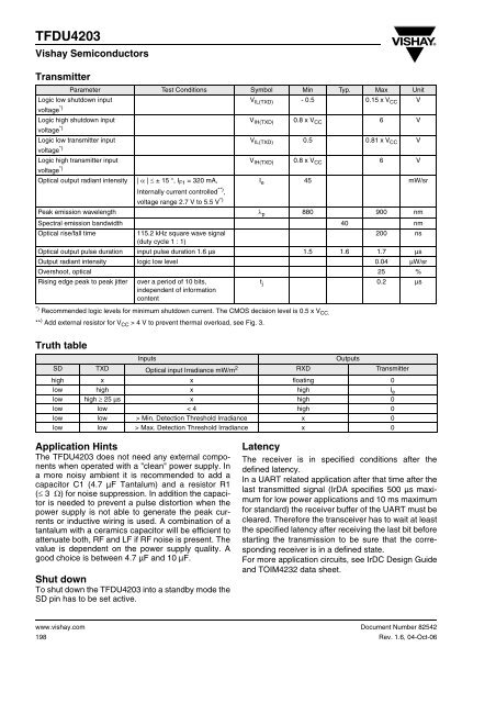
<strong>TFDU4203</strong>Vishay SemiconductorsTransmitterParameter Test Conditions Symbol Min Typ. Max UnitLogic low shutdown inputV IL(TXD) - 0.5 0.15 x V CC Vvoltage *)Logic high shutdown inputV IH(TXD) 0.8 x V CC 6 Vvoltage *)Logic low transmitter inputV IL(TXD) 0.5 0.81 x V CC Vvoltage *)Logic high transmitter inputV IH(TXD) 0.8 x V CC 6 Vvoltage *)Optical output radiant intensity | α | ≤ ± 15 °, I F1 = 320 mA,I e 45 mW/srvoltage range 2.7 V to 5.5 V *)Internally current controlled **) ,Peak emission wavelength λ p 880 900 nmSpectral emission bandwidth 40 nmOptical rise/fall time115.2 kHz square wave signal200 ns(duty cycle 1 : 1)Optical output pulse duration input pulse duration 1.6 µs 1.5 1.6 1.7 µsOutput radiant intensity logic low level 0.04 µW/srOvershoot, optical 25 %Rising edge peak to peak jitter over a period of 10 bits,t j 0.2 µsindependent of in<strong>for</strong>mationcontent*) Recommended logic levels <strong>for</strong> minimum shutdown current. The CMOS decision level is 0.5 x V CC.** ) Add external resistor <strong>for</strong> V CC > 4 V to prevent thermal overload, see Fig. 3.Truth tableInputsOutputsSD TXD Optical input Irradiance mW/m 2 RXD Transmitterhigh x x floating 0low high x high I elow high ≥ 25 µs x high 0low low < 4 high 0low low > Min. Detection Threshold Irradiance x 0low low > Max. Detection Threshold Irradiance x 0Application HintsThe <strong>TFDU4203</strong> does not need any external componentswhen operated with a "clean" power supply. Ina more noisy ambient it is recommended to add acapacitor C1 (4.7 µF Tantalum) and a resistor R1(≤ 3 Ω) <strong>for</strong> noise suppression. In addition the capacitoris needed to prevent a pulse distortion when thepower supply is not able to generate the peak currentsor inductive wiring is used. A combination of atantalum with a ceramics capacitor will be efficient toattenuate both, RF and LF if RF noise is present. Thevalue is dependent on the power supply quality. Agood choice is between 4.7 µF and 10 µF.Shut downTo shut down the <strong>TFDU4203</strong> into a standby mode theSD pin has to be set active.LatencyThe receiver is in specified conditions after thedefined latency.In a UART related application after that time after thelast transmitted signal (IrDA specifies 500 µs maximum<strong>for</strong> low power applications and 10 ms maximum<strong>for</strong> standard) the receiver buffer of the UART must becleared. There<strong>for</strong>e the transceiver has to wait at leastthe specified latency after receiving the last bit be<strong>for</strong>estarting the transmission to be sure that the correspondingreceiver is in a defined state.For more application circuits, see IrDC Design Guideand TOIM4232 data sheet.www.vishay.com198Document Number 82542Rev. 1.6, 04-Oct-06