Download Commander II Instruction Manual PDF file
Download Commander II Instruction Manual PDF file
Download Commander II Instruction Manual PDF file

Create successful ePaper yourself
Turn your PDF publications into a flip-book with our unique Google optimized e-Paper software.
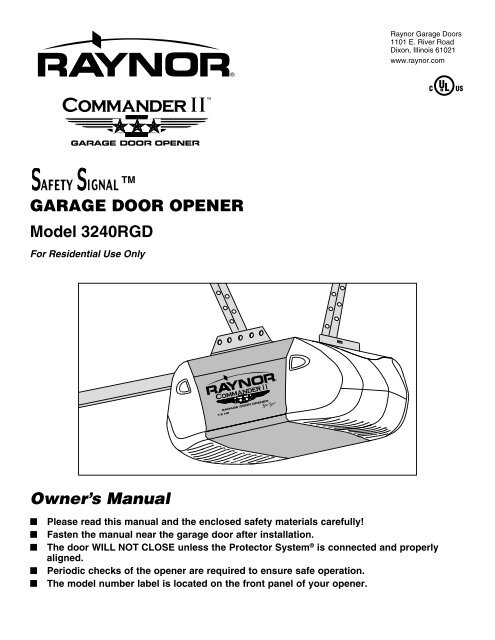
Raynor Garage Doors1101 E. River RoadDixon, Illinois 61021www.raynor.comTMGARAGE DOOR OPENERModel 3240RGDFor Residential Use OnlyOwner’s <strong>Manual</strong>■■■■■Please read this manual and the enclosed safety materials carefully!Fasten the manual near the garage door after installation.®The door WILL NOT CLOSE unless the Protector System is connected and properlyaligned.Periodic checks of the opener are required to ensure safe operation.The model number label is located on the front panel of your opener.
Table of ContentsINTRODUCTION 2-5Safety symbol and signal word review ....................................... 2Preparing your garage door ........................................................ 3Tools needed .............................................................................. 3Planning ..................................................................................... 4Carton inventory ......................................................................... 5Hardware inventory ..................................................................... 5ASSEMBLY 6Fasten rail to the motor unit ....................................................... 6INSTALLATION 7-22Installation safety instructions .................................................... 7Determine the header bracket location ....................................... 8Install the header bracket ............................................................ 9Attach the rail to the header bracket ......................................... 10Install the Protector System ® ..............................................11-13Position the opener ................................................................... 14Hang the opener ....................................................................... 15Install the door control ............................................................. 16Install the lights ....................................................................... 17Attach the emergency release rope and handle ........................ 17Electrical requirements ............................................................. 18Complete safety reversing sensor installation........................... 18Fasten the door bracket .......................................................19-20Connect the door arm to the trolley .....................................21-22ADJUSTMENT 23-25Adjust the travel limits .............................................................. 23Adjust the force ........................................................................ 24Test the safety reversal system................................................. 25Test the Protector System ® ...................................................... 25OPERATION 26-30Operation safety instructions .................................................... 26Using your garage door opener ................................................ 26Using the wall-mounted door control ....................................... 27To open the door manually ....................................................... 27Care of your garage door opener .............................................. 28Having a problem? .................................................................... 29Diagnostic chart ........................................................................ 30PROGRAMMING 31-32To add or reprogram a hand-held remote control .................... 31To erase all codes ..................................................................... 313-Button remotes ...................................................................... 31To add, reprogram or changea Keyless Entry PIN .................................................................. 32REPAIR PARTS 33-34Rail assembly parts .................................................................. 33Installation parts ....................................................................... 33Motor unit assembly parts ........................................................ 34ACCESSORIES 35REPAIR PARTS AND SERVICE 36WARRANTY 36IntroductionSafety Symbol and Signal Word ReviewThis garage door opener has been designed and tested to offer safe service provided it is installed, operated, maintained and tested instrict accordance with the instructions and warnings contained in this manual.MechanicalElectricalWhen you see these Safety Symbols and Signal Words on thefollowing pages, they will alert you to the possibility of seriousinjury or death if you do not comply with the warnings thataccompany them. The hazard may come from somethingmechanical or from electric shock. Read the warnings carefully.When you see this Signal Word on the following pages, it willalert you to the possibility of damage to your garage door and/orthe garage door opener if you do not comply with the cautionarystatements that accompany it. Read them carefully.2
1Preparing your garage doorBefore you begin:• Disable locks.• Remove any ropes connected to garage door.• Complete the following test to make sure your garage door isbalanced and is not sticking or binding:1. Lift the door about halfway as shown. Release the door. Ifbalanced, it should stay in place, supported entirely by itssprings.2. Raise and lower the door to see if there is any binding orsticking.If your door binds, sticks, or is out of balance, call a trained doorsystems technician.To prevent possible SERIOUS INJURY OR DEATH:• ALWAYS call a trained door systems technician if garagedoor binds, sticks, or is out of balance. An unbalancedgarage door may not reverse when required.• NEVER try to loosen, move or adjust garage door, doorsprings, cables, pulleys, brackets or their hardware, ALL ofwhich are under EXTREME tension.• Disable ALL locks and remove ALL ropes connected togarage door BEFORE installing and operating garage dooropener to avoid entanglement.To prevent damage to garage door and opener:• ALWAYS disable locks BEFORE installing and operating theopener.• ONLY operate garage door opener at 120V, 60 Hz to avoidmalfunction and damage.Sectional DoorOne-Piece DoorTools neededDuring assembly, installation and adjustment of the opener,instructions will call for hand tools as illustrated below.PencilCarpenter'sLevel (Optional)2Tape MeasureHack SawWire CuttersDrill3/16", 5/16" and5/32" Drill BitsPliersClaw HammerStepladder1/2" and 3/8" Socketsand WrenchScrewdriverAdjustable End Wrench3
PlanningIdentify the type and height of your garage door. Survey your garage area to see if any of the conditions below apply to yourinstallation. Additional materials may be required. You may find it helpful to refer back to this page and the accompanying illustrationsas you proceed with the installation of your opener.Sectional Door InstallationFINISHED CEILINGHorizontal and vertical reinforcementis needed for lightweight garage doors(fiberglass, steel, aluminum, door withglass panels, etc.). See page 19 for details.RailSupport bracket &fastening hardwareis required.See page 15.Header WallTorsionSpringORExtensionSpringMotor UnitVerticalCenterlineof GarageDoor— — — — — — — —WallmountedDoorControlAccess DoorSafety Reversing SensorSafety ReversingGap between floor Sensorand bottom of doormust not exceed 1/4" (6 mm).One-Piece Door without TrackFINISHED CEILINGSupport bracket &fastening & hardwareis hardware required. is See required.page See page 15. 19.RailMotorUnitHeader WallOne-Piece Door with TrackAccessDoorWall-mountedDoor ControlAccessDoorHeaderWallSafety ReversingGap between floorSensorand bottom of door must not exceed 1/4" (6 mm).Safety Reversing SensorSafetyReversing SensorSafetyReversing SensorGap between floorand bottom of doormust not exceed 1/4" (6 mm).4
Carton InventoryYour garage door opener is packaged in two cartons whichcontain the motor unit and all parts illustrated below. Accessorieswill depend on the model purchased.If anything is missing, carefully check the packing material. Partsmay be stuck in the foam. Hardware for installation is also listedbelow.LOCKLIGHTMulti-FunctionDoor Control PanelSAFETY SIGNAL 3-Button Remote Control (1)CEILING MOUNT ONLYUP2 Conductor Bell WireWhite & White/RedRemote ControlVisor ClipHeader BracketCurved DoorArm SectionRailSprocket CouplingMotor Unit with 2 Light LensesTrolleyDoor BracketSafety SensorBracket (2)The Protector System ®(2) Safety Reversing Sensors(1 Sending Eye and 1 Receiving Eye)with 2-Conductor White & White/BlackBell Wire attachedSafety LabelsandLiteratureStraight DoorArm SectionRail AssemblyCoupling Sleeve (1)Hex Bolt 1/4"-20 x 5/8" (4)Nut 1/4" - 20 (4)Installation HardwareHex Bolt 5/16"-18x7/8" (4)Lag Screw 5/16"-9x1-5/8" (2)Lag Screw 5/16"-18x1-7/8" (2)Clevis Pin 5/16"x2-3/4" (1)Clevis Pin 5/16"x1-1/4" (1)Clevis Pin 5/16"x1" (1)Nut 5/16"-18 (4)Lock Washer 5/16" (4)Screw 6ABx1-1/4" (2)Screw 6-32x1" (2)Self-Threading Screw 1/4"-14x5/8" (2)Insulated Staples (30)Ring Fastener (3)Drywall Anchors (2)Carriage Bolt 1/4"-20x1/2" (2)Wing Nut 1/4"-20 (2)RopeHandle5
Assembly Step 1Fasten the Rail to the Motor UnitHARDWARE SHOWN ACTUAL SIZETo avoid installation difficulties, do not run the garage dooropener until instructed to do so.To aid in assembly and installation, replace the foam packingaround the motor unit. Remove it after Installation Step 5.• Working on a level surface, align the rail assembly with themotor unit, as shown.• Slip the coupling over the rail sprocket.• Slide the rail through the motor unit bracket until the couplingfits securely over the motor unit sprocket.• Align the two bolt holes in the rail with those in the motor unitbracket. Insert four 1/4"-20x7/16" hex bolts. Tighten securelywith a 3/8" socket wrench.• Turn release arm down to disengage trolley.• Slide the trolley onto and along the bottom of the rail. Aligntrolley with rack and turn release arm up tore-engage trolley. Be certain to install it facing correctly: thetrolley release arm must be horizontal (lock position), withits arrow pointed away from the motor unit.Hex Bolts1/4-20x7/16"Hex Bolt 1/4-20x7/16"Motor UnitBracket Motor UnitSprocketCouplingRailSprocketHex Bolts1/4"-20x7/16"Rail AssemblyFoam PackagingArrow must point upRelease armRackTrolleyTo motor unit6
WARNINGINSTALLATIONIMPORTANT INSTALLATION INSTRUCTIONSWARNINGTo reduce the risk of SEVERE INJURY or DEATH:1. READ AND FOLLOW ALL INSTALLATION WARNINGS ANDINSTRUCTIONS.2. Install garage door opener ONLY on properly balanced andlubricated garage door. An improperly balanced door maynot reverse when required and could result in SEVEREINJURY OR DEATH.3. ALL repairs to cables, spring assemblies and otherhardware MUST be made by a trained door systemstechnician BEFORE installing opener.4. Disable ALL locks and remove ALL ropes connected togarage door BEFORE installing opener to avoidentanglement.5. Install garage door opener 7 feet (2.13 m) or more abovefloor.6. Mount emergency release handle 6 feet (1.83 m) abovefloor.7. NEVER connect garage door opener to power source untilinstructed to do so.8. NEVER wear watches, rings or loose clothing whileinstalling or servicing opener. They could be caught ingarage door or opener mechanisms.9. Install wall-mounted garage door control:• within sight of the garage door• out of reach of children at minimum height of 5 feet(1.5 m)• away from ALL moving parts of the door10. Place entrapment warning label on wall next to garage doorcontrol.11. Place manual release/safety reverse test label in plain viewon inside of garage door.12. Upon completion of installation, test safety reversal system.Door MUST reverse on contact with a 1-1/2" (3.8 cm) highobject (or a 2x4 laid flat) on the floor.7
Installation Step 1Determine the Header Bracket LocationTo prevent possible serious injury or death:• Header bracket MUST be RIGIDLY fastened to structuralsupport on header wall or ceiling, otherwise garage doormight not reverse when required. DO NOT install headerbracket over drywall.• Concrete anchors MUST be used if mounting header bracketor 2x4 into masonry.• NEVER try to loosen, move or adjust garage door, springs,cables, pulleys, brackets, or their hardware, ALL of whichare under EXTREME tension.• ALWAYS call a trained door systems technician if garagedoor binds, sticks, or is out of balance. An unbalancedgarage door might not reverse when required.Header WallUnfinishedCeilingVertical Centerlineof Garage DoorLevel(optional)2x42x4OPTIONALCEILINGMOUNTFORHEADERBRACKETStructuralSupportsInstallation procedures vary according to garage door types.Follow the instructions which apply to your door.1. Close the door and mark the inside vertical centerline of thegarage door.2. Extend the line onto the header wall above the door.You can fasten the header bracket within 4 feet(1.22 m) of the left or right of the door center only if atorsion spring or center bearing plate is in the way; or youcan attach it to the ceiling (see page 9) when clearance isminimal. (It may be mounted on the wall upside down ifnecessary, to gain approximately 1/2" (1 cm).If you need to install the header bracket on a 2x4 (on wall orceiling), use lag screws (not provided) to securely fasten the2x4 to structural supports as shown here and on page 8.3. Open your door to the highest point of travel as shown. Drawan inter secting horizontal line on the header wall above thehigh point:• 3" (7.5 cm) above the high point for sectional door and onepiecedoor with track.• 8" (20 cm) above the high point for one-piece door withouttrack.This height will provide travel clearance for the top edge of thedoor.NOTE: If the total number of inches exceeds the heightavailable in your garage, use the maximum height possible, orrefer to page 9 for ceiling installation.Header Wall3" (7.5 cm)TrackHighest Pointof TravelDoorSectional door with curved trackHeader Wall8" (20 cm)DoorHeader Wall3" (7.5 cm)Highest Pointof TravelOne-piece door with horizontal trackHeader Wall8" (20 cm)TrackDoorHighestPointof TravelDoorHighestPointof TravelJambHardwarePivotOne-piece door without track:jamb hardwareOne-piece door without track:pivot hardware8
Installation Step 2Install the Header BracketYou can attach the header bracket either to the wall above thegarage door, or to the ceiling. Follow the instructions which willwork best for your particular requirements. Do not install theheader bracket over drywall. If installing into masonry, useconcrete anchors (not provided).Wall Header Bracket Installation• Center the bracket on the vertical centerline with the bottomedge of the bracket on the horizontal line as shown (with thearrow pointing toward the ceiling).• Mark the vertical set of bracket holes (do not use the holesdesignated for ceiling mount). Drill 3/16" pilot holes and fastenthe bracket securely to a structural support with the hardwareprovided.HARDWARE SHOWN ACTUAL SIZE2x4StructuralSupportHorizontalLineWall Mounting HolesHeaderWallCEILING MOUNT ONLYUPOptionalWall Mounting HolesHeaderBracketCEILING MOUNT ONLYUPThe nail hole is forpositioning only.You must use lag screwsto mount the header bracket.VerticalCenterlineof Garage DoorLag Screws5/16"-9x1-5/8"Door SpringLag Screw5/16"-9 x 1-5/8"Highest Point ofGarage Door TravelGarageDoorVerticalCenterlineof Garage DoorCeiling Header Bracket Installation• Extend the vertical centerline onto the ceiling as shown.• Center the bracket on the vertical mark, no more than 6"(15 cm) from the wall. Make sure the arrow is pointing towardthe wall. The bracket can be mounted flush against the ceilingwhen clearance is minimal.• Mark the side holes. Drill 3/16" pilot holes and fasten bracketsecurely to a structural support with the hardware provided.– Finished Ceiling –HeaderBracketVerticalCenterlineof Garage Door6" (15 cm)MaximumUPCeiling Mounting HolesDoorSpringLag Screws5/16"-9x1-5/8"CEILING MOUNT ONLYThe nail hole is forpositioning only.You must use lag screwsto mount the header bracket.UPGarage DoorVerticalCenterlineof Garage DoorHeader Wall9
Installation Step 3Attach the Rail to the Header Bracket• Position the opener on the garage floor below the headerbracket. Use packing material as a protective base. NOTE: If thedoor spring is in the way you’ll need help. Have someone holdthe opener securely on a temporary support to allow the rail toclear the spring.• Position the rail bracket against the header bracket.• Align the bracket holes and join with a clevis pin as shown.• Insert a ring fastener to secure.Header WallHeader BracketRail BracketRailHeader BracketRing FastenerSpacerGarageDoorClevis Pin5/16"x2-3/4"SpacerRailBracketRailOpener Carton orTemporarySupportHARDWARE SHOWN ACTUAL SIZEClevis Pin5/16"x2-3/4" Ring Fastener Spacer10
Installation Step 4Install The Protector System ®The safety reversing sensor must be connected and alignedcorrectly before the garage door opener will move in the downdirection.IMPORTANT INFORMATION ABOUT THE SAFETY REVERSINGSENSORSWhen properly connected and aligned, the sensor will detect anobstacle in the path of its electronic beam. The sending eye (withan amber indicator light) transmits an invisible light beam to thereceiving eye (with a green indicator light). If an obstructionbreaks the light beam while the door is closing, the door will stopand reverse to full open position, and the opener lights will flash10 times.The units must be installed inside the garage so that the sendingand receiving eyes face each other across the door, no more than6" (15 cm) above the floor. Either can be installed on the left orright of the door as long as the sun never shines directly into thereceiving eye lens.The mounting brackets are designed to clip onto the track ofsectional garage doors without additional hardware.Be sure power is not connected to the garage door openerBEFORE installing the safety reversing sensor.To prevent SERIOUS INJURY OR DEATH from a closinggarage door:• Correctly connect and align the safety reversing sensor. Thisrequired safety device MUST NOT be disabled.• Install the safety reversing sensor so beam is NO HIGHERthan 6" (15 cm) above garage floor.If it is necessary to mount the units on the wall, the brackets mustbe securely fastened to a solid surface such as the wall framing.Extension brackets (see accessories) are available if needed. Ifinstalling in masonry construction, add a piece of wood at eachlocation to avoid drilling extra holes in masonry if repositioning isnecessary.The invisible light beam path must be unobstructed. No part of thegarage door (or door tracks, springs, hinges, rollers or otherhardware) may interrupt the beam while the door is closing.Safety Reversing Sensor6" (15 cm) max. above floorInvisible Light BeamProtection AreaSafety Reversing Sensor6" (15 cm) max. above floorFacing the door from inside the garage11
Installing the BracketsBe sure power to the opener is disconnected. Install and alignthe brackets so the sensors will face each other across the garagedoor, with the beam no higher than 6" (15 cm) above the floor.They may be installed in one of three ways, as follows:Garage door track installation (preferred):• Slip the curved arms over the rounded edge of each door track,with the curved arms facing the door. Snap into place againstthe side of the track. It should lie flush, with the lip hugging theback edge of the track, as shown in Figure 1.If your door track will not support the bracket securely, wallinstallation is recommended.Wall installation (Figures 2 & 3):• Place the bracket against the wall with curved arms facing thedoor. Be sure there is enough clearance for the sensor beam tobe unobstructed.• If additional depth is needed, an extension bracket (seeAccessories) or wood blocks can be used.• Use bracket mounting holes as a template to locate and drill (2)3/16" diameter pilot holes on the wall at each side of the door,no higher than 6" (15 cm) above the floor.• Attach brackets to wall with lag screws (not provided).• If using extension brackets or wood blocks, adjust right and leftassemblies to the same distance out from the mountingsurface. Make sure all door hardware obstructions are cleared.Floor installation (Figure 4):• Use wood blocks or extension brackets(see Accessories) to elevate sensor brackets so the lenses willbe no higher than 6" (15 cm) above the floor.• Carefully measure and place right and left assemblies at thesame distance out from the wall. Be sure all door hardwareobstructions are cleared.• Fasten to the floor with concrete anchors as shown.Figure 1 1Figure 2 2Figure 3 3DOOR TRACK MOUNT (RIGHT SIDE)DoorTrackSensorBracketLipWALL MOUNT (RIGHT SIDE)InsideGarageWallWALL MOUNT (RIGHT SIDE)InsideGarageWallIndicatorLightLensFasten Wood Block to Wall withLag Screws (Not Provided)IndicatorLightLensSensorBracketLag Screws(Not Provided)ExtensionBracket(See Accessories)(Provided withExtension Bracket)(Provided withExtensionBracket)LensIndicatorLightSensorBracketFigure 4 4FLOOR MOUNT (RIGHT SIDE)InsideGarageWallAttach withConcrete Anchors(Not Provided)LensIndicatorLightSensorBracket12
Mounting and Wiring the Safety Reversing Sensors• Slide a 1/4"-20x1/2" carriage bolt head into the slot on eachsensor. Use wing nuts to fasten sensors to brackets, withlenses pointing toward each other across the door. Be sure thelens is not obstructed by a bracket extension (Figure 5).• Finger tighten the wing nuts.Recommended Wire Routing1. Using insulated staples, run the wires from both sensors to therail at the door header (Figure 6).2. Run the wires through wire clips at the top of the rails.NOTE: If your access door is near the garage door, you maychoose to install the door control at this time and run the doorcontrol wire along the rail with the sensor wires.Figure 5Carriage Bolt1/4"-20x1/2"Carriage Bolt1/4"-20x1/2"HARDWARE SHOWN ACTUAL SIZEWing Nut1/4"-20Wing Nut1/4"-20LensStaplesFigure 6Wire ClipsSensor WireBell WireRailSafety Reversing SensorInvisible Light BeamProtection AreaSafety ReversingSensor13
Installation Step 5Position the OpenerFollow instructions which apply to your door type as illustrated.Sectional Door or One-Piece Door with TrackA 2x4 laid flat is convenient for setting an ideal door-to-raildistance.• Raise the opener onto a stepladder. You will need help at thispoint if the ladder is not tall enough.• Open the door all the way and place a 2x4 laid flat on the topsection beneath the rail.• If the top section or panel hits the trolley when you raisethe door, pull down on the trolley release arm to disconnectinner and outer sections. Slide the outer trolley toward themotor unit. The trolley can remain disconnected untilInstallation Step 13 is completed.To prevent damage to garage door, rest garage door openerrail on 2x4 placed on top section of door.DoorTop of Door2x4 is used to determinethe correct mounting heightfrom ceiling.ENGAGEDTrolleyRelease ArmRELEASEDOne-Piece Door without TrackA 2x4 on its side is convenient for setting an ideal door-to-raildistance.• Remove foam packaging.• Raise the opener onto a stepladder. You will need help atthis point if the ladder is not tall enough.• Open the door all the way and place a 2x4 on its side on thetop section of the door beneath the rail.• The top of the door should be level with the top of the motorunit. Do not position the opener more than 4" (10 cm) abovethis point.Top of Door2x4 is used to determinethe correct mounting heightfrom ceiling.14
Installation Step 6Hang the OpenerThree representative installations are shown. Yours may bedifferent. Hanging brackets should be angled(Figure 1) to provide rigid support. On finished ceilings (Figure 2and Figure 3), attach a sturdy metal bracket to structural supportsbefore installing the opener. This bracket and fastening hardwareare not provided.1. Measure the distance from each side of the motor unit to thestructural support.2. Cut both pieces of the hanging bracket to required lengths.3. Drill 3/16" pilot holes in the structural supports.4. Attach one end of each bracket to a support with5/16"-18x1-7/8" lag screws.5. Fasten the opener to the hanging brackets with5/16"-18x7/8" hex bolts, lock washers and nuts.6. Check to make sure the rail is centered over the door (or in linewith the header bracket if the bracket is not centered above thedoor).7. Remove the 2x4. Operate the door manually. If the door hitsthe rail, raise the header bracket.NOTE: DO NOT connect power to opener at this time.To avoid possible SERIOUS INJURY from a falling garage dooropener, fasten it SECURELY to structural supports of thegarage. Concrete anchors MUST be used if installing ANYbrackets into masonry.Figure 1MeasureDistanceBolt 5/16"-18x7/8"Lock Washer 5/16"Nut 5/16"-18Figure 2Bracket(Not Provided)HiddenSupportStructuralSupportsLag Screws5/16"-18x1-7/8"FINISHED CEILINGLag Screws5/16"-18x1-7/8"Bolt 5/16"-18x7/8"Lock Washer 5/16"Nut 5/16"-18(Not Provided)Bolt 5/16"-18x7/8"Lock Washer 5/16"Nut 5/16"-18HARDWARE SHOWN ACTUAL SIZELag Screw 5/16"-18x1-7/8"Figure 3Lag Screws5/16"-18x1-7/8"FINISHED CEILINGHex Bolt5/16"-18x7/8" Nut 5/16"-18 Lock Washer 5/16"Bolt 5/16"-18x7/8"Lock Washer 5/16"Nut 5/16"-18(Not Provided)Bolt 5/16"-18x7/8"Lock Washer 5/16"Nut 5/16"-1815
975KG31975KG31Installation Step 7Install the Door ControlLocate door control within sight of the door at a minimum heightof 5 feet (1.5 m) where small children cannot reach, and awayfrom moving parts of the door and door hardware. Theinstallation surface must be smooth and flat. If installing intodrywall (Figure 1), drill 5/32" holes and use anchors provided. Forpre-wired installations (as in new home construction), it may bemounted to a single gang box (Figure 2). NOTE: After installation,a green indicator light behind the cover will indicate properconnection. If not lit, the Lock and Light features will not function(reverse wires to correct).1. Strip 7/16" (11 mm) of insulation from one end of bell wire andconnect to the two screw terminals on back of door control bycolor: white wire to 2 and white/red wire to the 1 (Figure 3).2. Remove white cover by gently prying at slot in top of the coverwith a small flat head screwdriver. Fasten with 6ABx1-1/4" selfthreadingscrews (drywall installation) or 6-32x1" machinescrews (into gang box) as follows:• Drill and install bottom screw, allowing 1/8" (3 mm) toprotrude above wall surface.• Position bottom of door control on screw head and slidedown to secure. Adjust screw for snug fit.• Install top screw with care to avoid cracking plastic housing.Do not overtighten.• Insert bottom tabs and snap on cover.NOTE: The push bar may stick if the door control is not mountedon a smooth surface. If a click is not heard when pressing thepush bar, loosen the two mounting screws or relocate the doorcontrol to a smoother surface.3. (Standard installation only) Run bell wire up wall and acrossceiling to motor unit. Use insulated staples to secure wire inseveral places. Do not pierce wire with a staple, creating ashort or open circuit. If your access door is near the garagedoor, you may run this wire with the Safety Reversing Sensorwires along the top of the rail. See page 13.4. Insert all wires through the opening on top of motor unit abovethe terminal block on the back panel (Figure 4).5. Strip 7/16" (11 mm) of insulation from each set of wires. Insertdoor control wire into quick-connect terminals by color: whitewire to white, white/red wire to red.Separate white and white/black wires sufficiently to connect tothe opener quick-connect terminals. Twist like colored wirestogether. Insert wires into quick-connect holes: white to whiteand white/black to grey (Figure 4).NOTE: When connecting multiple door controls to the opener,twist same color wires together. Insert wires into quick-connectholes: white to white and red/white to red.6. Use tacks or staples to permanently attach entrapment warninglabel to wall near door control, and manual release/safetyreverse test label in a prominent location on inside of garagedoor.NOTE: DO NOT connect the power and operate the opener at thistime. The trolley will travel to the full open position but will notreturn to the close position until the sensor beam is connectedand properly aligned. See Step 11 on page 18.To prevent possible SERIOUS INJURY or DEATH fromelectrocution:• Be sure power is not connected BEFORE installing doorcontrol.• Connect ONLY to 24 VOLT low voltage wires.To prevent possible SERIOUS INJURY OR DEATH from aclosing garage door:• Install door control within sight of garage door, out of reachof children at a minimum height of 5 feet (1.5 m), and awayfrom ALL moving parts of door.• NEVER permit children to operate or play with door controlpush buttons or remote control transmitters.• Activate door ONLY when it can be seen clearly, is properlyadjusted, and there are no obstructions to door travel.• ALWAYS keep garage door in sight until completely closed.NEVER permit anyone to cross path of closing garage door.Figure Figure 1 1 STANDARDINSTALLATIONLOCKLIGHTTo ReplaceInsert Bottom Tabs FirstFigure 3Multi-function (std installation)6AB x 1-1/4" ScrewDoor ControlConnectionsHARDWARE SHOWN ACTUAL SIZEMulti-function (pre-wired)6-32 x 1" ScrewTop Mounting HoleTerminalScrewsBell WireBottom Mounting HoleTo release or insert wire,push in tab with screwdriver tipRed White Grey7/16" (11 mm)Figure Figure 2 2PRE-WIREDINSTALLATIONLOCKLIGHTTo ReplaceInsert Bottom Tabs FirstFigure 4InsulatedStaplesDrywallAnchors24 VoltBell Wire16Strip wire 7/16" (11 mm)
Installation Step 8Install the Lights• Press the release tabs on both sides of lens. Gently rotate lensback and downward until the lens hinge is in the fully openposition. Do not remove the lens.• Install a 100 watt maximum light bulb in each socket. Lightbulb size should be A19, standard neck only. The lights will turnON and remain lit for approximately 4-1/2 minutes when poweris connected. Then the lights will turn OFF.• Reverse the procedure to close the lens.• Use A19, standard neck garage door opener bulbs forreplacement.NOTE: Use only standard light bulbs. The use of short neck orspeciality light bulbs may overheat the endpanel or light socket.To prevent possible OVERHEATING of the endpanel or lightsocket:• DO NOT use short neck or specialty light bulbs.• DO NOT use halogen bulbs. Use ONLY incandescent.To prevent damage to the opener:• DO NOT use bulbs larger than 100W.• ONLY use A19 size bulbs.100 Watt (Max)Standard Light BulbRelease Tab100 Watt (Max)Standard Light BulbLensHingeInstallation Step 9Attach the Emergency Release Rope and Handle• Thread one end of the rope through the hole in the top of thered handle so “NOTICE” reads right side up as shown. Securewith an overhand knot at least 1" (2.5 cm) from the end of therope to prevent slipping.• Thread the other end of the rope through the hole in the releasearm of the outer trolley.• Adjust rope length so the handle is 6 feet (1.83 m) above thefloor. Secure with an overhand knot.NOTE: If it is necessary to cut the rope, heat seal the cut end witha match or lighter to prevent unraveling.To prevent possible SERIOUS INJURY OR DEATH from afalling garage door:• If possible, use emergency release handle to disengagetrolley ONLY when garage door is CLOSED. Weak or brokensprings or unbalanced door could result in an open doorfalling rapidly and/or unexpectedly.• NEVER use emergency release handle unless garagedoorway is clear of persons and obstructions.• NEVER use handle to pull door open or closed. If rope knotbecomes untied, you could fall.TrolleyTrolley Release ArmEmergencyRelease HandleNOTICEOverhandKnot17
Installation Step 10Electrical RequirementsTo avoid installation difficulties, do not run the opener at thistime.To reduce the risk of electric shock, your garage door opener hasa grounding type plug with a third grounding pin. This plug willonly fit into a grounding type outlet. If the plug doesn’t fit into theoutlet you have, contact a qualified electrician to install the properoutlet.To prevent possible SERIOUS INJURY OR DEATH fromelectrocution or fire:• Be sure power is not connected to the opener, anddisconnect power to circuit BEFORE removing cover toestablish permanent wiring connection.• Garage door installation and wiring MUST be in compliancewith ALL local electrical and building codes.• NEVER use an extension cord, 2-wire adapter, or changeplug in ANY way to make it fit outlet. Be sure the opener isgrounded.RIGHTWRONGPERMANENT WIRINGCONNECTIONIf permanent wiring is required by your local code, refer to thefollowing procedure.To make a permanent connection through the 7/8" hole in the topof the motor unit:• Remove the motor unit cover screws and set the cover aside.• Remove the attached 3-prong cord.• Connect the black (line) wire to the screw on the brassterminal; the white (neutral) wire to the screw on the silverterminal; and the ground wire to the green ground screw. Theopener must be grounded.• Reinstall the cover.Ground TabGreenGround ScrewGround WireWhite WireBlackWireBlack WireTo avoid installation difficulties, do not run the opener untilStep 11 below.Installation Step 11Complete Safety Reversing Sensor InstallationALIGNING THE SAFETY REVERSING SENSORSPlug in the opener. The indicator lights in both the sending andreceiving eyes will glow steadily if wiring connections andalignment are correct.The sending eye amber indicator light will glow regardless ofalignment or obstruction. If the green indicator light in thereceiving eye is off, dim, or flickering (and the invisible light beampath is not obstructed), alignment is required.• Loosen the sending eye wing nut and readjust, aiming directlyat the receiving eye. Lock in place.• Loosen the receiving eye wing nut and adjust the sensorvertically and/or horizontally until it receives the sender’s beam.When the green indicator light glows steadily, tighten the wingnut.TROUBLESHOOTING THE SAFETY REVERSING SENSORS1. If the sending eye indicator light does not glow steadily afterinstallation, check for:• Electric power to the opener.• A short in the white or white/black wires. These can occur atstaples, or at opener connections.• Incorrect wiring between sensors and opener.• A broken wire.2. If the sending eye indicator light glows steadily but thereceiving eye indicator light doesn’t:• Check alignment.• Check for an open wire to the receiving eye.3. If the receiving eye indicator light is dim, realign either sensor.NOTE: When the invisible beam path is obstructed or misalignedwhile the door is closing, the door will reverse. If the door isalready open, it will not close. The opener lights will blink 10times (if bulbs are not installed, 10 clicks can be heard). Seepage 11.18
Installation Step 12Fasten the Door BracketFollow instructions which apply to your door type as illustratedbelow or on the following page.A horizontal reinforcement brace should be long enough to besecured to two or three vertical supports. A verticalreinforcement brace should cover the height of the top panel.Figure 1 shows one piece of angle iron as the horizontal brace.For the vertical brace, 2 pieces of angle iron are used to create aU-shaped support. The best solution is to check with your garagedoor manufacturer for an opener installation door reinforcementkit.NOTE: Many door reinforcement kits provide for direct attachmentof the clevis pin and door arm. In this case you will not need thedoor bracket; proceed to Step 13.Fiberglass, aluminum or lightweight steel garage doors WILLREQUIRE reinforcement BEFORE installation of door bracket.Contact your door manufacturer for reinforcement kit.HeaderBracketDoorBracketLocationSectional Doors1. Center the door bracket on the previously marked verticalcenterline used for the header bracket installation. Note correctUP placement, as stamped inside the bracket.2. Position the top edge of the bracket 2"-4" (5-10 cm) below thetop edge of the door, OR directly below any structural supportacross the top of the door.3. Mark, drill holes and install as follows, depending on yourdoor’s construction:Metal or light weight doors using a vertical angle iron bracebetween the door panel support and the door bracket:• Drill 3/16" fastening holes. Secure the door bracket using thetwo 1/4"-14x5/8" self-threading screws (Figure 2A).• Alternately, use two 5/16" bolts, lock washers and nuts (notprovided) (Figure 2B).Metal, insulated or light weight factory reinforced doors:• Drill 3/16" fastening holes. Secure the door bracket using theself-threading screws (Figure 3).Wood Doors:• Use top and bottom or side to side door bracket holes. Drill5/16" holes through the door and secure bracket with 5/16"x2"carriage bolts, lock washers and nuts (not provided) (Figure 4).NOTE: The 1/4"-14x5/8" self-threading screws are not intended foruse on wood doors.Figure 1VerticalReinforcementDoorBracketSelf-ThreadingScrew1/4"-14x5/8"Figure 2AVerticalCenterlineof GarageDoorVerticalCenterlineof Garage DoorUPHORIZONTAL AND VERTICALREINFORCEMENT IS NEEDEDFOR LIGHTWEIGHT GARAGEDOORS (FIBERGLASS,ALUMINUM, STEEL, DOORSWITH GLASS PANEL, ETC.).(NOT PROVIDED)(Not Provided)Bolt5/16"-18x2"VerticalReinforcementVerticalCenterlineof Garage DoorDoorBracketLock Washer5/16" Nut5/16"-18(Not Provided)Bolt5/16"x2"Figure 2BUPInside Edgeof Door orReinforcement BoardUPHARDWARESHOWNACTUAL SIZESelf-ThreadingScrew1/4"-14x5/8"VerticalCenterlineof Garage DoorUPSelf-ThreadingScrew1/4"-14x5/8"VerticalCenterlineof GarageDoorFigure 4Figure 319
One-Piece DoorsPlease read and comply with the warnings and reinforcementinstructions on the previous page. They apply to one-piece doorsalso.• Center the door bracket on the top of the door, in line with theheader bracket as shown. Mark either the left and right, or thetop and bottom holes.• Metal Doors: Drill 3/16" pilot holes and fasten the bracket withthe 1/4"-14x5/8" self-threading screws provided.• Wood Doors: Drill 5/16" holes and use 5/16"x2" carriage bolts,lock washers and nuts (not provided) or 5/16"x1-1/2" lagscrews (not provided) depending on your installation needs.HARDWARE SHOWNACTUAL SIZENOTE: The door bracket may be installed on the top edge of thedoor if required for your installation (refer to the dotted lineoptional placement drawing).Self-Threading Screw1/4"-14x5/8"Header Wall2x4 SupportFinished CeilingDoorBracketSelf-ThreadingScrew1/4"-14x5/8"Top of Door(InsideGarage)HeaderBracketTop Edgeof DoorDoorBracketOptionalPlacementMETAL DOOROptionalPlacementof DoorBracketVerticalCenterline ofGarage DoorHORIZONTAL AND VERTICALREINFORCEMENT IS NEEDEDFOR LIGHTWEIGHT GARAGEDOORS (FIBERGLASS,ALUMINUM, STEEL, DOORSWITH GLASS PANEL, ETC.).(NOT PROVIDED)Nut5/16"-18DoorBracketLockWasher5/16"Top of Door(InsideGarage)Top Edgeof DoorOptionalPlacementCarriage Bolt5/16"x2"(Not Provided)For a door with no exposed framing,or for the optional installation, uselag screws 5/16"x1-1/2" (Not Provided)to fasten door bracket.WOOD DOOR20
Installation Step 13Connect Door Arm to TrolleyFollow instructions which apply to your door type as illustratedbelow and on the following page.InnerTrolleyOuterTrolleySectional Doors Only• Make sure garage door is fully closed. Pull the emergencyrelease handle to disconnect the outer trolley from the innertrolley. Slide the outer trolley back (away from the door) about2" (5 cm) as shown in Figures 1, 2 and 3.• Figure 1:– Fasten straight door arm section to outer trolley with the5/16"x1" clevis pin. Secure the connection with a ringfastener.– Fasten curved section to the door bracket in the same way,using the 5/16"x1-1/4" clevis pin.• Figure 2:– Bring arm sections together. Find two pairs of holes that lineup and join sections. Select holes as far apart as possible toincrease door arm rigidity.• Figure 3, Hole alignment alternative:– If holes in curved arm are above holes in straight arm,disconnect straight arm. Cut about 6" (15 cm) from the solidend. Reconnect to trolley with cut end down as shown.– Bring arm sections together.– Find two pairs of holes that line up and join with bolts, lockwashers and nuts.• Pull the emergency release handle toward the opener at a 45°angle so that the trolley release arm is horizontal. Proceed toAdjustment Step 1, page 23. Trolley will re-engageautomatically when opener is operated.Figure 1Figure 2Nuts5/16"-18RingFastenerStraightDoor ArmDoorBracketClevis Pin5/16"x1-1/4"LockWashers5/16"Door BracketClevis Pin5/16"x1"Curved Door ArmBolts5/16"-18x7/8"EmergencyReleaseHandleHARDWARE SHOWN ACTUAL SIZENut 5/16"-18Lock Washer 5/16"Ring FastenerNuts5/16"-18LockWashers5/16"Clevis Pin5/16"x1" (Trolley)Clevis Pin5/16"x1-1/4" (Door Bracket)Hex Bolt5/16"-18x7/8"Bolts5/16"-18x7/8"Cut this endFigure 321
All One-Piece Doors1. Assemble the door arm, Figure 4:• Fasten the straight and curved door arm sections together tothe longest possible length (with a 2 or 3 hole overlap).• With the door closed, connect the straight door arm sectionto the door bracket with the5/16"x1-1/4" clevis pin.• Secure with a ring fastener.2. Adjustment procedures, Figure 5:• On one-piece doors, before connecting the door arm to thetrolley, the travel limits must be adjusted. Limit adjust mentscrews are located on the left side panel as shown on page23. Follow adjustment procedures below.• Open door adjustment: decrease UP travel limit– Turn the UP limit adjustment screw counter-clockwise 4turns.– Press the Door Control push button. The trolley will travelto the fully open position.– <strong>Manual</strong>ly raise the door to the open position (parallel tothe floor), and lift the door arm to the trolley. The armshould touch the trolley just in back of the door armconnector hole. Refer to the fully open trolley/door armpositions in the illustration. If the arm does not extend farenough, adjust the limit further. One full turn equals 2" (5cm) of trolley travel.• Closed door adjustment: decrease DOWN travel limit– Turn the DOWN limit adjustment screw clockwise4 complete turns.Figure 4DoorBracketClevis Pin5/16"x1-1/4"StraightArmBolts5/16"-18x7/8RingFastenerLockWashers5/16"Nuts5/16"-18CurvedDoor Arm– Press the Door Control push button. The trolley will travelto the fully closed position.– <strong>Manual</strong>ly close the door and lift the door arm to thetrolley. The arm should touch the trolley just ahead of thedoor arm connector hole. Refer to the fully closed trolley/door arm positions in the illustration. If the arm is behindthe connector hole, adjust the limit further. One full turnequals 2" (5 cm) of trolley travel.3. Connect the door arm to the trolley:• Close the door and join the curved arm to the connector holein the trolley with the remaining clevis pin. It may benecessary to lift the door slightly to make the connection.• Secure with a ring fastener.• Run the opener through a complete travel cycle. If the doorhas a slight “backward” slant in full open position as shownin the illustration, decrease the UP limit until the door isparallel to the floor.NOTE: When setting the up limit on the following page, the doorshould not have a “backward” slant when fully open as illustratedbelow. A slight backward slant will cause unnecessary buckingand/or jerking operation as the door is being opened or closedfrom the fully open position.Figure 5Inner TrolleyOuter TrolleyDoor ArmConnector HoleDoor ArmEmergencyRelease HandleClosedDoorInner TrolleyOuter TrolleyCorrect AngleDoor ArmConnector HoleOpen DoorDoor withBackward Slant(Incorrect)22
Adjustment Step 1Adjust the UP and DOWN Travel LimitsLimit adjustment settings regulate the points at which the doorwill stop when moving up or down.To operate the opener, press the Door Control push bar. Run theopener through a complete travel cycle.• Does the door open and close completely?• Does the door stay closed and not reverse unintentionally whenfully closed?If your door passes both of these tests, no limit adjustments arenecessary unless the reversing test fails (Adjustment Step 3,page 25).Adjustment procedures are outlined below. Read the procedurescarefully before proceeding to Adjustment Step 2. Use ascrewdriver to make limit adjustments. Run the opener through acomplete travel cycle after each adjustment.NOTE: Repeated operation of the opener during adjustmentprocedures may cause the motor to overheat and shut off. Simplywait 15 minutes and try again. If anything interferes with thedoor’s upward travel, it will stop. If anything interferes with thedoor’s downward travel (including binding or unbalanced doors),it will reverse.Without a properly installed safety reversal system, persons(particularly small children) could be SERIOUSLY INJURED ORKILLED by a closing garage door.• Incorrect adjustment of garage door travel limits will interferewith proper operation of safety reversal system.• If one control (force or travel limits) is adjusted, the othercontrol may also need adjustment.• After ANY adjustments are made, the safety reversal systemMUST be tested. Door MUST reverse on contact with 1-1/2"(3.8 cm) high object (or 2x4 laid flat) on floor.To prevent damage to vehicles, be sure fully open doorprovides adequate clearance.How and Whe0n to Adjust the Limits• If the door does not open completely but opens at least 5feet (1.5 m):Increase up travel. Turn the UP limit adjustment screwclockwise. One turn equals 2" (5 cm) of travel.NOTE: To prevent the trolley from hitting the cover protectionbolt, keep a minimum distance of 2-4" (5-10 m) between thetrolley and the bolt.• If door does not open at least 5 feet (1.5 m):Adjust the UP (open) force as explained in Adjustment Step 2.• If the door does not close completely:Increase down travel. Turn the down limit adjustment screwcounterclockwise. One turn equals 2" (5 cm) of travel.If door still won’t close completely and the trolley bumps intothe pulley bracket (page 4), try lengthening the door arm(page 21) and decreasing the down limit.• If the opener reverses in fully closed position:Decrease down travel. Turn the down limit adjustment screwclockwise. One turn equals 2" (5 cm) of travel.Limit Adjustment ScrewsADJUSTMENT LABELLeft Side Panel• If the door reverses when closing and there is no visibleinterference to travel cycle:If the opener lights are flashing, the Safety Reversing Sensorsare either not installed, misaligned, or obstructed. SeeTroubleshooting, page 18.Test the door for binding: Pull the emergency release handle.<strong>Manual</strong>ly open and close the door. If the door is binding orunbalanced, call for a trained door systems technician. If thedoor is balanced and not binding, adjust the DOWN (close)force. See Adjustment Step 2.23
KGKGAdjustment Step 2Adjust the ForceForce adjustment controls are located on the back panel of themotor unit. Force adjustment settings regulate the amount ofpower required to open and close the door.If the forces are set too light, door travel may be interrupted bynuisance reversals in the down direction and stops in the updirection. Weather conditions can affect the door movement, sooccasional adjustment may be needed.The maximum force adjustment range is about 3/4 of acomplete turn. Do not force controls beyond that point. Turnforce adjustment controls with a screwdriver.NOTE: If anything interferes with the door’s upward travel, it willstop. If anything interferes with the door’s downward travel(including binding or unbalanced doors), it will reverse.Without a properly installed safety reversal system, persons(particularly small children) could be SERIOUSLY INJURED orKILLED by a closing garage door.• To much force on garage door will interfere with properoperation of safety reversal system.• NEVER increase force beyond minimum amount required toclose garage door.• NEVER use force adjustments to compensate for a binding orsticking garage door.• If one control (force or travel limits) is adjusted, the othercontrol may also need adjustment.• After ANY adjustments are made, the safety reversal systemMUST be tested. Door MUST reverse on contact with 1-1/2"(3.8 cm) high object (or 2x4 laid flat) on floor.How and When to Adjust the Forces1. Test the DOWN (close) force• Grasp the door bottom when the door is about halfway throughDOWN (close) travel. The door should reverse. Reversalhalfway through down travel does not guarantee reversal on a1-1/2" (3.8 cm) obstruction. See Adjustment Step 3, page 25. Ifthe door is hard to hold or doesn’t reverse, DECREASE theDOWN (close) force by turning the control counterclockwise.Make small adjustments until the door reverses normally. Aftereach adjustment, run the opener through a complete cycle.• If the door reverses during the down (close) cycle and theopener lights aren’t flashing, INCREASE DOWN (close) forceby turning the control clockwise. Make small adjustments untilthe door completes a close cycle. After each adjustment, runthe opener through a complete travel cycle. Do not increase theforce beyond the minimum amount required to close the door.2. Test the UP (open) force• Grasp the door bottom when the door is about halfway throughUP (open) travel. The door should stop. If the door is hard tohold or doesn’t stop, decrease UP (open) force by turning thecontrol counterclockwise. Make small adjustments until thedoor stops easily and opens fully. After each adjustment, runthe opener through a complete travel cycle.• If the door doesn’t open at least 5 feet (1.5 m), Increase UP(open) force by turning the control clockwise. Make smalladjustments until door opens completely. Readjust the UP limitif necessary. After each adjustment, run the opener through acomplete travel cycle.Back Panel97FORCE ADJUSTMENT LABEL531975ForceAdjustmentControls31AntennaKGOpen ForceKGClose Force24
Adjustment Step 3Test the Safety Reversal SystemTEST• With the door fully open, place a 1-1/2" (3.8 cm) board (or a2x4 laid flat) on the floor, centered under the garage door.• Operate the door in the down direction. The door must reverseon striking the obstruction.ADJUST• If the door stops on the obstruction, it is not traveling farenough in the down direction. Increase the DOWN limit byturning the DOWN limit adjustment screw counterclockwise 1/4turn.NOTE: On a sectional door, make sure limit adjustments do notforce the door arm beyond a straight up and down position.See the illustration on page 21.REPEAT THE TEST.• When the door reverses on the 1-1/2" (3.8 cm) board, removethe obstruction and run the opener through 3 or 4 completetravel cycles to test adjustment.Without a properly installed safety reversal system, persons(particularly small children) could be SERIOUSLY INJURED orKILLED by a closing garage door.• Safety reversal system MUST be tested every month.• If one control (force or travel limits) is adjusted, the othercontrol may also need adjustment.• After ANY adjustments are made, the safety reversal systemMUST be tested. Door MUST reverse on contact with 1-1/2"(3.8 cm) high object (or 2x4 laid flat) on the floor.IMPORTANT SAFETY CHECK:Test the Safety Reverse System after:• Each adjustment of door arm length, limits, or force controls.• Any repair to or adjustment of the garage door (includingsprings and hardware).• Any repair to or buckling of the garage floor.• Any repair to or adjustment of the opener.Adjustment Step 4Test the Protector System ®• Press the remote control push button to open the door.• Place the opener carton in the path of the door.• Press the remote control push button to close the door. Thedoor will not move more than an inch (2.5 cm), and the openerlights will flash.The garage door opener will not close from a remote if theindicator light in either sensor is off (alerting you to the fact thatthe sensor is misaligned or obstructed).If the opener closes the door when the safety reversing sensoris obstructed (and the sensors are no more than 6" (15 cm)above the floor), call for a trained door systems technician.1-1/2" (3.8 cm) board(or a 2x4 laid flat)Without a properly installed safety reversing sensor, persons(particularly small children) could be SERIOUSLY INJURED orKILLED by a closing garage door.Safety Reversing SensorSafety Reversing Sensor25
WARNINGOperationIMPORTANT SAFETY INSTRUCTIONSWARNINGTo reduce the risk of SEVERE INJURY or DEATH:1. READ AND FOLLOW ALL WARNINGS ANDINSTRUCTIONS.2. ALWAYS keep remote controls out of reach of children.NEVER permit children to operate or play with garage doorcontrol push buttons or remote controls.3. ONLY activate garage door when it can be seen clearly, it isproperly adjusted, and there are no obstructions to doortravel.4. ALWAYS keep garage door in sight until completely closed.NO ONE SHOULD CROSS THE PATH OF THE MOVINGDOOR.5. NO ONE SHOULD GO UNDER A STOPPED, PARTIALLYOPEN DOOR.6. If possible, use emergency release handle to disengagetrolley ONLY when garage door is closed. Weak or brokensprings or unbalanced door could result in an open doorfalling rapidly and/or unexpectedly.7. NEVER use emergency release handle unless garagedoorway is clear of persons and obstructions.8. NEVER use handle to pull garage door open or closed. Ifrope knot becomes untied, you could fall.9. If one control (force or travel limits) is adjusted, the othercontrol may also need adjustment.10. After ANY adjustments are made, the safety reversalsystem MUST be tested.11. Safety reversal system MUST be tested every month.Garage door MUST reverse on contact with 1-1/2" (3.8 cm)high object (or a 2 x 4 laid flat) on the floor.12. ALWAYS keep garage door properly balanced (see page 3).An improperly balanced door may not reverse whenrequired and could result in SEVERE INJURY OR DEATH.13. ALL repairs to cables, spring assemblies and otherhardware, ALL of which are under extreme tension, MUSTbe made by a trained door systems technician.14. ALWAYS disconnect electric power to garage door openerBEFORE making ANY repairs or removing covers.15. SAVE THESE INSTRUCTIONS.Using Your Garage Door OpenerYour SAFETY SIGNAL TM opener and hand-held remote controlhave been factory-set to a matching code which changes witheach use, randomly accessing over 100 billion new codes. Youropener will operate with up to eight SAFETY SIGNAL TM remotecontrols and one SAFETY SIGNAL TM Keyless Entry System. If youpurchase a new remote, or if you wish to deactivate any remote,follow the instructions in the Programming section.Activate your opener with any of the following:• The hand-held Remote Control: Hold the large push buttondown until the door starts to move.• The wall-mounted Door Control: Hold the push button or bardown until the door starts to move.• The Keyless Entry (See Accessories): If provided with yourgarage door opener, it must be programmed before use. SeeProgramming.When the opener is activated (with the safety reversing sensorcorrectly installed and aligned):1. If open, the door will close. If closed, it will open.2. If closing, the door will reverse.3. If opening, the door will stop.4. If the door has been stopped in a partially open position, it willclose.5. If obstructed while closing, the door will reverse. If theobstruction interrupts the sensor beam, the opener lights willblink for five seconds.6. If obstructed while opening, the door will stop.7. If fully open, the door will not close when the beam is broken.The sensor has no effect in the opening cycle.If the sensor is not installed, or is misaligned, the door won’tclose from a hand-held remote. However, you can close the doorwith the Door Control, the Outside Keylock, or Keyless Entry, ifyou activate them until down travel is complete. If you releasethem too soon, the door will reverse.The opener lights will turn on under the following conditions:when the opener is initially plugged in; when power is restoredafter interruption; when the opener is activated.They will turn off automatically after 4-1/2 minutes or provideconstant light when the Light feature on the Multi-Function DoorControl is activated. Bulb size is A19. Bulb power is 100 wattsmaximum.Light feature: Lights will also turn on when someone walksthrough the open garage door. With a Multi-Function DoorControl, this feature may be turned off as follows: With the openerlights off, press and hold the light button for 10 seconds, until thelight goes on, then off again. To restore this feature, start with theopener lights on, then press and hold the light button for 10seconds until the light goes off, then on again.26
Using the Wall-Mounted Door ControlThe Multi-Function Door ControlPress the push bar to open or close the door.Press again to reverse the door during theclosing cycle or to stop the door while it’sopening.Light featurePress the Light button to turn the opener lighton or off. It will not control the opener lights when the door is inmotion. If you turn it on and then activate the opener, the light willremain on for 4-1/2 minutes. Press again to turn it off sooner. The4-1/2 minute interval can be changed to 1-1/2, 2-1/2, or 3-1/2minutes as follows: Press and hold the Lock button until the lightblinks (about 10 seconds). A single blink indicates that the timeris reset to 1-1/2 minutes. Repeat the procedure and the light willblink twice, resetting the timer to 2-1/2 minutes. Repeat again fora 3-1/2 minute interval, etc., up to a maximum of four blinks and4-1/2 minutes.Lock featureDesigned to prevent operation of the door from hand-held remotecontrols. However, the door will open and close from the DoorControl, the Outside Keylock and the Keyless Entry Accessories.To activate, press and hold the Lock button for 2 seconds. Thepush bar light will flash as long as the Lock feature is on.To turn off, press and hold the Lock button again for 2 seconds.The push bar light will stop flashing. The Lock feature will alsoturn off whenever the “Learn” button on the motor unit panel isactivated.Additional features when used with the 3-Button hand-heldremoteTo control the opener lights:In addition to operating the door, you may program the remote tooperate the lights.1. With the door closed, press and hold a smallremote button that you want to control thelight.2. Press and hold the Light button on theMulti-Function door control.3. While holding the Light button, press and hold the Lock buttonon the door control.4. After the opener lights flash, release all buttons.LOCKLIGHTPushButtonLockButtonLightButtonTo Open the Door <strong>Manual</strong>lyTo prevent possible SERIOUS INJURY OR DEATH from a fallinggarage door:• If possible, use emergency release handle to disengagetrolley ONLY when garage door is CLOSED. Weak or brokensprings or unbalanced door could result in an open doorfalling rapidly and/or unexpectedly.• NEVER use emergency release handle unless garage doorwayis clear of persons and obstructions.• NEVER use handle to pull door open or closed. If rope knotbecomes untied, you could fall.Disconnect Trolley:The door should be fully closedif possible. Pull down on theemergency release handle (sothat the trolley release armsnaps into a vertical position)and lift the door manually.The lockout feature prevents thetrolley from reconnectingautomatically, and the door canbe raised and lowered manuallyas often as necessary.To Re-Connect the Trolley:Pull the emergency releasehandle toward the opener at a45° angle so that the trolleyrelease arm is horizontal. Thetrolley will reconnect on thenext UP or DOWN operation,either manually or by using thedoor control or remote.NOTICELOCKOUT POSITION(MANUAL DISCONNECT)EmergencyRelease Handle(Pull at 45° angle)TO RECONNECTNOTICETrolleyTrolley ReleaseArm (in <strong>Manual</strong>Disconnect Position)TrolleyTrolleyReleaseArm27
Care of Your OpenerLimit and force adjustments:Weather conditions may cause someminor changes in door operationrequiring some re-adjustments,particularly during the first year ofoperation.Pages 23 and 24 refer to the limit andforce adjustments. Only a screwdriver isrequired. Follow the instructions carefully.FORCE CONTROLS975KG31975KGLIMIT CONTROLS31The Remote Control BatteryTo prevent possible SERIOUS INJURY OR DEATH:• NEVER allow small children near batteries.• If battery is swallowed, immediately notify doctor.To reduce risk of fire, explosion or chemical burn:• Replace ONLY with 3V2032 coin batteries.• DO NOT recharge, disassemble, heat above 212°F (100°C) orincinerate.Repeat the safety reverse test(Adjustment Step 3, page 25) after anyadjustment of limits or force.Maintenance ScheduleOnce a Month• <strong>Manual</strong>ly operate door. If it is unbalanced or binding, call atrained door systems technician.• Check to be sure door opens & closes fully. Adjust limits and/or force if necessary. See pages 23 and 24.• Repeat the safety reverse test. Make any necessaryadjustments. See Adjustment Step 3.Once a Year• Oil door rollers, bearings and hinges. The opener does notrequire additional lubrication. Do not grease the door tracks.The lithium battery should producepower for up to 5 years.To replace battery, use the visor clipor screwdriver blade to pry open thecase as shown. Insert batterypositive side up (+).Dispose of old battery properly.Replace the battery with only3V2032 coin cell batteries.Batterypositiveside up (+)NOTICE: To comply with FCC and or Industry Canada (IC) rules, adjustment or modifications of thisreceiver and/or transmitter are prohibited, except for changing the code setting or replacing thebattery. THERE ARE NO OTHER USER SERVICEABLE PARTS.Tested to Comply with FCC Standards for HOME OR OFFICE USE. Operation is subject to thefollowing two conditions: (1) this device may not cause harmful interference, and (2) this devicemust accept any interference received, including interference that may cause undesired operation.28
KGKGHaving a Problem?1. My door will not close and the light bulbs blink on my motorunit: The safety reversing sensor must be connected andaligned correctly before the garage door opener will move in thedown direction.• Verify the safety sensors are properly installed, aligned andfree of any obstructions. Refer to Installation Step 10: InstallThe Protector System ® .• Check diagnostic LED for flashes on the motor unit thenrefer to the on the following page.2. My remotes will not activate the door:• Verify your Premium door control is not blinking. If it isblinking, deactivate the Lock Mode following the instructionsfor Using the Multi-Function Door Control.• Reprogram remotes following the programming instructions.Refer to Programming.• If remote will still not activate your door, check diagnosticLED for flashes on motor unit then refer to Diagnostic Charton the following page.Safety Reversing SensorSending Eye Safety ReversingSensor (Amber Indicator Light)DiagnosticsLocated OnMotor UnitLED orDiagnosticLED“Learn”ButtonReceiving Eye Safety ReversingSensor (Green Indicator Light)3. My door reverses for no apparent reason: Repeat safetyreverse test after adjustments to force or travel limits. The needfor occasional adjustment for the force and limit settings isnormal. Weather conditions in particular can affect door travel.• <strong>Manual</strong>ly check door for balance or any binding problems.• Refer to Adjustment Step 2, Adjust the force.4. My door reverses for no apparent reason after fully closingand touching the floor: Repeat safety reverse test afteradjustments to force or travel limits. The need for occasionaladjustment for the force and limit settings is normal. Weatherconditions in particular can affect door travel.• Refer to Adjustment Step 1, Adjust the UP and DOWN TravelLimits. Decrease down travel by turning down limitadjustment screw clockwise.5. My lights will not turn off when door is open:• The garage door opener is equipped with a security lightfeature. This feature activates the light on when the safetysensor beam has been obstructed. Refer to Operationsection; Using the Wall Mounted Door Control, LightFeature.29
KGKGDiagnosticsLocated OnMotor UnitInstalledSafety ReversingSensorSafety Reversing SensorDiagnostic Chart1 FLASHSafety reversing sensorswire open (broken ordisconnected).OR2 FLASHESSafety reversing sensorswire shorted or black/whitewire reversed.LED orDiagnosticLED“Learn”ButtonYour garage door opener is programmed with self-diagnosticcapabilities. The “Learn” button/diagnostic LED will flash a number oftimes then pause signifying it has found a potential issue. ConsultDiagnostic Chart below.Symptom: One or both of the Indicator lights on the safety sensors do not glow steady.• Inspect sensor wires for a short (staple in wire), correct wiring polarity (black/white wiresreversed), broken or disconnected wires, replace/attach as needed.• Disconnect all wires from back of motor unit.• Remove sensors from brackets and shorten sensor wires to 1-2 ft (30-60 cm) from backeach of sensor.• Reattach sending eye to motor unit using shortened wires. If sending eye indicator lightglows steadily, attach the receiving eye.• Align sensors, if the indicator lights glow replace the wires for the sensors. If the sensorindicator lights do not light, replace the safety sensors.3 FLASHESDoor control or wireshorted.4 FLASHESSafety reversing sensorsslightly misaligned(dim or flashing LED).5 FLASHESMotor overheated or possibleRPM sensor failure. Unplugto reset.6 FLASHESMotor Circuit Failure.Replace ReceiverLogic Board.Symptom: LED is not lit on door control.• Inspect door control/wires for a short (staple in wire), replace as needed.• Disconnect wires at door control, touch wires together. If motor unit activates, replace doorcontrol.• If motor unit does not activate, disconnect door control wires from motor unit. Momentarilyshort across red and white terminals with jumper wire. If motor unit activates, replace doorcontrol wires.Symptom: Sending indicator light glows steadily, receiving indicator light is dim orflashing.• Realign receiving eye sensor, clean lens and secure brackets.• Verify door track is firmly secured to wall and does not move.Symptom: Motor has over heated; the motor unit does not operate;RPM Sensor = Short travel 6-8" (15-20 cm).• Unplug unit to reset. Try to operate motor unit, check diagnostic code.• If it is still flashing 5 times and motor unit moves 6-8" (15-20 cm), replace RPM sensor.• If motor unit doesn’t operate, motor unit is overheated. Wait 30 minutes and retry. If motorunit still will not operate replace logic board.Symptom: Motor unit doesn’t operate.• Replace logic board because motor rarely fails.30
91735KG91735KGLOCKLIGHTProgrammingNOTICE: If this SAFETY SIGNAL TM garage door opener is operated with a non-rolling code transmitter, the technical measure in thereceiver of the garage door opener, which provides security against code-theft devices, will be circumvented. The owner of thecopyright in the garage door opener does not authorize the purchaser or supplier of the non-rolling code transmitter to circumvent thattechnical measure.Your garage door opener has already been programmed at the factory to operate with your hand-held remote control. The door willopen and close when you press the large push button.Below are instructions for programming your opener to operate with additional SAFETY SIGNAL TM 315MHz remote controls.To Add and Reprogram an Additional Hand-held Remote ControlUsing the “Learn” ButtonUsing the Multi-Function Door Control1. Press and release the “learn” button onthe motor unit. The learn indicator lightwill glow steadily for 30 seconds.1. Press and hold the button on the handheldremote* that you wish to operateyour garage door.2. Within 30 seconds, press and hold thebutton on the hand-held remote* that youwish to operate your garage door.3. Release the button when the motor unitlights blink. It has learned the code. Iflight bulbs are not installed, two clickswill be heard.2. While holding the remote button, pressand hold the light button on the Multi-Function Door Control.3. Continue holding both buttons while youpress the push bar on the Multi-FunctionDoor Control (all three buttons are held).4. Release buttons when the motor unitlights blink. It has learned the code. Iflight bulbs are not installed, two clickswill be heard.LOCKLOCKLIGHTLIGHTTo Erase All Codes From Motor Unit MemoryTo deactivate any unwanted remote, firsterase all codes:Press and hold the “learn” button on motorunit until the learn indicator light goes out(approximately 6 seconds). All previouscodes are now erased. Reprogram eachremote or keyless entry you wish to use.*3-Button RemotesIf provided with your garage door opener, the large button isfactory programmed to operate it.Additional buttons on anySAFETY SIGNAL TM 3-buttonremote or mini-remote can beprogrammed to operate otherSAFETY SIGNAL TM garagedoor openers.31
LOCKLIGHTTo Add, Reprogram or Change a Keyless Entry PINNOTE: Your new Keyless Entry must be programmed to operate your garage door opener.Using the “Learn” ButtonUsing the Multi-Function Door Control1. Press and release the “learn” button onmotor unit. The learn indicator light willglow steadily for 30 seconds.2. Within 30 seconds, enter a four digitpersonal identification number (PIN) ofyour choice on the keypad. Then pressand hold the enter button.NOTE: This method requires two people if the Keyless Entry isalready mounted outside the garage.1. Enter a four digit personal identificationnumber (PIN) of your choice on thekeypad. Then press and hold enter.2. While holding the ENTER button, pressand hold the LIGHT button on theMulti-Function Door Control.3. Release the button when the motor unitlights blink. It has learned the code. Iflight bulbs are not installed, two clickswill be heard.3. Continue holding the ENTER and LIGHTbuttons while you press the push baron the Multi-Function Door Control (allthree buttons are held).LOCKLOCKLIGHTLIGHTTo change an existing, known PINIf the existing PIN is known, it may be changed by one personwithout using a ladder.1. Press the four buttons for the present PIN, then press and holdthe # button.2. The opener light will blink twice. Release the # button.3. Press the new 4-digit PIN you have chosen, then press Enter.The motor unit lights will blink once when the PIN has beenlearned.Test by pressing the new PIN, then press Enter. The door shouldmove.To set a temporary PINYou may authorize access by visitors or service people with atemporary 4-digit PIN. After a programmed number of hours ornumber of accesses, this temporary PIN expires and will nolonger open the door. It can be used to close the door even afterit has expired. To set a temporary PIN:1. Press the four buttons for your personal entry PIN (not the lasttemporary PIN), then press and hold the ✽ button.The opener light will blink three times. Release the button.4. Release buttons when the motor unitlights blink. It has learned the code. Iflight bulbs are not installed, two clickswill be heard.2. Press the temporary 4-digit PIN you have chosen, then pressEnter.The opener light will blink four times.3. To set the number of hours this temporary PIN will work, pressthe number of hours (up to 255), then press ✽.OR3. To set the number of times this temporary PIN will work, pressthe number of times (up to 255), then press #.The opener light will blink once when the temporary PIN has beenlearned.Test by pressing the four buttons for the temporary PIN, thenpress Enter. The door should move. If the temporary PIN was setto a certain number of openings, remember that the test has usedup one opening. To clear the temporary password, repeat steps1-3, setting the number of hours or times to 0 in step 3.One Button Close: Opener can be closed by pressing only the ENTER button if the one button close feature has been activated. Thisfeature has been activated at the factory. To activate or deactivate this feature press and hold buttons 1 and 9 for 10 seconds. Thekeypad will blink twice when the one button close is active. The keypad will blink four times when one button close is deactivated.32
Repair PartsRail Assembly Parts53617Installation Parts1LOCKLIGHTNOTICE24432KEY PARTNO. NO. DESCRIPTION1 41A6353 Hardware bag(includes sprocket coupling)2 81C275 Rack3 41A6262 Complete trolley assembly4 3077SD Screw Drive one-piece rail7' (2.1 m)5 3088SD Screw Drive One-piece 8' (2.4 m)6 41A4836 Drive sprocket kit7 25C20 Sprocket coupling8 41A6312 Rail End BracketNOT SHOWN9 28A143 Rail Wire Clips591086CEILING MOUNT ONLYUP11712KEY PARTNO. NO. DESCRIPTION1 41A5273-6 Multi-function door control2 41A2828 Emergency release rope & handle3 373RGD 3-button remote control4 10A20 3V 2032 Lithium battery (1 required)5 29B137 Visor clip6 41A5047 Door bracket w/clevis pin & fastener7 178B34 Straight door arm section8 41A4353 Header bracket w/clevis pin & fastener9 41A5034 Safety sensor kit: receiving and sending eyeswith 3' (.9 m) 2-conductor bell wire attached10 41A5266-1 Safety sensor bracket11 41B4494-1 2-Conductor bell wire: white & white/red12 178B35 Curved door arm sectionNOT SHOWN13 41A4675-7 Installation hardware bag (see page 3)14 114A3332 Owner’s manual33
Motor Unit Assembly Parts9 9a13211014346a5128761411KEY PARTNO NO. DESCRIPTION1 31C568 Drive shaft cover2 41B4245 Line cord3 30B620 Capacitor – 1/2 HP4 41A3150 Terminal block w/screws5 41D4671 Limit switch assembly6 41A6241 Motor drive assy. complete6a 20B21-1 Drive belt7 41C4672 Screw drive RPM kitKEY PARTNO. NO. DESCRIPTION8 41A4837-1 Worm gear and retainer9 41A6635 Low voltage wire harness9a 41A6634 High voltage wire harness10 41AS050R2 Receiver logic board11 41A5525-58 Cover (Model 3240)12 41C22-1 Drive coupling hub13 175B88 Light socket14 108D79 Light lens34
SENDPASSREADYENROLLENROLLFAILRETRYCLOSEDOPENAccessories1702LMOutside Quick Release:Required for a garage with NO access door.Enables homeowner to open garage doormanually from outside by disengagingtrolley.371RGD1-Button SAFETY SIGNAL TM Remote Control:Includes visor clip.59LMOutside Keylock:Operates the garage door automaticallyfrom the outside when remote control isnot handy.373RGD3-Button SAFETY SIGNAL TM RemoteControl:Includes visor clip.41A5281Extension Brackets:(Optional) For safety reversing sensorinstallation onto the wall or floor.370LM3-Button Mini-Remote Control withSecurity✚ ® :With key ring and fastening strip.98LMLOCK LIGHTMotion Detecting Control Panel:Multi-function door control with motionsensor that automatically turns openerlights on for 5 minutes when it detects aperson entering the garage. Sensor can beeasily deactivated when desired.915LMGarage Door Monitor:Security for the largest door of your home!Tells you if your garage door is open orclosed. Monitors up to 4 garage doors byadding additional sensor modules.902LM/903LM377LG2 & 3 Door Multi-Function Wall Control:Ideal for homes with up to three garagedoors. Combine up to three controls intoone wall control panel for a neat compactappearance. Enhanced functions includeLock Feature to lock out outside radiosignals while you are away from home andturn opener lights on or off from the controlpanel.Wireless Keyless Entry withSecurity✚ ® :Enables homeowner to operate garage dooropener from outside by entering apassword on a specially designed keyboard.Also can add a temporary password forvisitors or service persons. This temporarypassword can be limited to a programmablenumber of hours or entries.916LM395LM379LM-10Garage Door Monitor Sensor:Additional accessory sensor for homes withmultiple garage doors.Remote Light Control :Enables homeowner to turn on a lamp,television or other appliance from their carwith their garage door opener remote or fromanywhere in their home with an additionalLiftMaster Security✚ ® remote.Fingerprint Keyless Entry:The system uses biometric technology thatenables an authorized user to gain access byscanning their fingerprint. The sensor strip onthe unit makes a numeric template of thefingerprint that is unique to that user. Theunit’s memory can store up to fourfingerprints.35
RAYNOR GARAGE DOORSSERVICE IS ON CALLOUR LARGE SERVICE ORGANIZATIONSPANS AMERICAINSTALLATION AND SERVICE INFORMATION IS AS NEARAS YOUR TELEPHONE FIVE DAYS A WEEK. SIMPLY DIALOUR TOLL FREE NUMBER:1-800-472-9667HOURS: (Central Std. Time)7:30 A.M. TO 4:30 P.M. - Monday through FridayFor professional installation, parts and service, contactyour local RAYNOR GARAGE DOORS distributor. Look forhim in the Yellow Pages, or visit our Dealer Locator on ourWebsite www.Raynor.com.HOW TO ORDERREPAIR PARTSSelling prices will be furnished on request or parts will beshipped at prevailing prices and you will be billed accordingly.WHEN ORDERING REPAIR PARTS, ALWAYS GIVE THEFOLLOWING INFORMATION:• PART NUMBER• PART NAME• MODEL NUMBERADDRESS ORDERS TO:RAYNOR GARAGE DOORSTechnical Support Group6050 S. Country Club RoadTucson, Arizona 85706SERVICE INFORMATIONTOLL FREE NUMBER:1-800-528-9131RAYNOR GARAGE DOOR OPENER ONE-YEAR LIMITED WARRANTYLIFETIME MOTOR WARRANTYRaynor (“Seller”) warrants to the first retail purchaser of this product, for the residence in which this product is originally installed, that it is free from defect in materialsand/or workmanship for a period of one year from the date of purchase and that the motor is free from defect in materials and/or workmanship for a lifetime from thedate of purchase. The proper operation of this product is dependent on your compliance with the instructions regarding installation, operation, maintenance and testing.Failure to comply strictly with those instructions will void this limited warranty in its entirety.If, during the limited warranty period, this product appears to contain a defect covered by this limited warranty, call 1-888-528-9131, toll free, before dismantling thisproduct. Then send this product, pre-paid and insured, to our service center for warranty repair. You will be advised of shipping instructions when you call. Pleaseinclude a brief description of the problem and a dated proof-of-purchase receipt with any product returned for warranty repair. Products returned to Seller for warrantyrepair, which upon receipt by Seller are confirmed to be defective and covered by this limited warranty, will be repaired or replaced (at Seller's sole option) at no costto you and returned pre-paid. Defective parts will be repaired or replaced with new or factory-rebuilt parts at Seller's sole option.ALL IMPLIED WARRANTIES FOR THE PRODUCT, INCLUDING BUT NOT LIMITED TO ANY IMPLIED WARRANTIES OF MERCHANTABILITY AND FITNESSFOR A PARTICULAR PURPOSE, ARE LIMITED IN DURATION TO THE 1 YEAR LIMITED WARRANTY PERIOD SET FORTH ABOVE [EXCEPT THE IMPLIEDWARRANTIES WITH RESPECT TO THE MOTOR, WHICH ARE LIMITED IN DURATION TO THE LIFETIME WARRANTY PERIOD FOR THE MOTOR], AND NOIMPLIED WARRANTIES WILL EXIST OR APPLY AFTER SUCH PERIOD. Some States do not allow limitations on how long an implied warranty lasts, so theabove limitation may not apply to you. THIS LIMITED WARRANTY DOES NOT COVER NON-DEFECT DAMAGE, DAMAGE CAUSED BY IMPROPER INSTAL-LATION, OPERATION OR CARE (INCLUDING, BUT NOT LIMITED TO ABUSE, MISUSE, FAILURE TO PROVIDE REASONABLE AND NECESSARY MAINTE-NANCE, UNAUTHORIZED REPAIRS OR ANY ALTERATIONS TO THIS PRODUCT), LABOR CHARGES FOR REINSTALLING A REPAIRED OR REPLACEDUNIT, REPLACEMENT OF BATTERIES AND LIGHT BULBS OR UNITS INSTALLED FOR NON-RESIDENTIAL USE.THIS LIMITED WARRANTY DOES NOT COVER ANY PROBLEMS WITH, OR RELATING TO, THE GARAGE DOOR OR GARAGE DOOR HARDWARE, INCLUD-ING BUT NOT LIMITED TO THE DOOR SPRINGS, DOOR ROLLERS, DOOR ALIGNMENT OR HINGES. THIS LIMITED WARRANTY ALSO DOES NOT COVERANY PROBLEMS CAUSED BY INTERFERENCE. ANY SERVICE CALL THAT DETERMINES THE PROBLEM HAS BEEN CAUSED BY ANY OF THESE ITEMSCOULD RESULT IN A FEE TO YOU.UNDER NO CIRCUMSTANCES SHALL SELLER BE LIABLE FOR CONSEQUENTIAL, INCIDENTAL OR SPECIAL DAMAGES ARISING IN CONNECTIONWITH USE, OR INABILITY TO USE, THIS PRODUCT. IN NO EVENT SHALL SELLER'S LIABILITY FOR BREACH OF WARRANTY, BREACH OF CONTRACT,NEGLIGENCE OR STRICT LIABILITY EXCEED THE COST OF THE PRODUCT COVERED HEREBY. NO PERSON IS AUTHORIZED TO ASSUME FOR US ANYOTHER LIABILITY IN CONNECTION WITH THE SALE OF THIS PRODUCT.Some states do not allow the exclusion or limitation of consequential, incidental or special damages, so the above limitation or exclusion may not apply to you. Thislimited warranty gives you specific legal rights, and you may also have other rights which vary from state to state.114A3332B© 2008, The Chamberlain Group, Inc.All Rights Reserved