Download Commander II Instruction Manual PDF file
Download Commander II Instruction Manual PDF file
Download Commander II Instruction Manual PDF file

You also want an ePaper? Increase the reach of your titles
YUMPU automatically turns print PDFs into web optimized ePapers that Google loves.
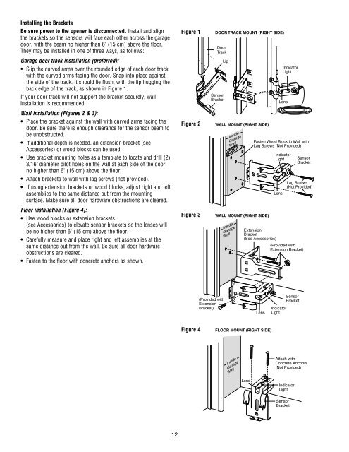
Installing the BracketsBe sure power to the opener is disconnected. Install and alignthe brackets so the sensors will face each other across the garagedoor, with the beam no higher than 6" (15 cm) above the floor.They may be installed in one of three ways, as follows:Garage door track installation (preferred):• Slip the curved arms over the rounded edge of each door track,with the curved arms facing the door. Snap into place againstthe side of the track. It should lie flush, with the lip hugging theback edge of the track, as shown in Figure 1.If your door track will not support the bracket securely, wallinstallation is recommended.Wall installation (Figures 2 & 3):• Place the bracket against the wall with curved arms facing thedoor. Be sure there is enough clearance for the sensor beam tobe unobstructed.• If additional depth is needed, an extension bracket (seeAccessories) or wood blocks can be used.• Use bracket mounting holes as a template to locate and drill (2)3/16" diameter pilot holes on the wall at each side of the door,no higher than 6" (15 cm) above the floor.• Attach brackets to wall with lag screws (not provided).• If using extension brackets or wood blocks, adjust right and leftassemblies to the same distance out from the mountingsurface. Make sure all door hardware obstructions are cleared.Floor installation (Figure 4):• Use wood blocks or extension brackets(see Accessories) to elevate sensor brackets so the lenses willbe no higher than 6" (15 cm) above the floor.• Carefully measure and place right and left assemblies at thesame distance out from the wall. Be sure all door hardwareobstructions are cleared.• Fasten to the floor with concrete anchors as shown.Figure 1 1Figure 2 2Figure 3 3DOOR TRACK MOUNT (RIGHT SIDE)DoorTrackSensorBracketLipWALL MOUNT (RIGHT SIDE)InsideGarageWallWALL MOUNT (RIGHT SIDE)InsideGarageWallIndicatorLightLensFasten Wood Block to Wall withLag Screws (Not Provided)IndicatorLightLensSensorBracketLag Screws(Not Provided)ExtensionBracket(See Accessories)(Provided withExtension Bracket)(Provided withExtensionBracket)LensIndicatorLightSensorBracketFigure 4 4FLOOR MOUNT (RIGHT SIDE)InsideGarageWallAttach withConcrete Anchors(Not Provided)LensIndicatorLightSensorBracket12