Download Commander II Instruction Manual PDF file
Download Commander II Instruction Manual PDF file
Download Commander II Instruction Manual PDF file

Create successful ePaper yourself
Turn your PDF publications into a flip-book with our unique Google optimized e-Paper software.
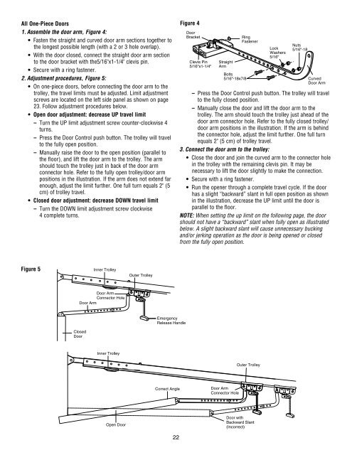
All One-Piece Doors1. Assemble the door arm, Figure 4:• Fasten the straight and curved door arm sections together tothe longest possible length (with a 2 or 3 hole overlap).• With the door closed, connect the straight door arm sectionto the door bracket with the5/16"x1-1/4" clevis pin.• Secure with a ring fastener.2. Adjustment procedures, Figure 5:• On one-piece doors, before connecting the door arm to thetrolley, the travel limits must be adjusted. Limit adjust mentscrews are located on the left side panel as shown on page23. Follow adjustment procedures below.• Open door adjustment: decrease UP travel limit– Turn the UP limit adjustment screw counter-clockwise 4turns.– Press the Door Control push button. The trolley will travelto the fully open position.– <strong>Manual</strong>ly raise the door to the open position (parallel tothe floor), and lift the door arm to the trolley. The armshould touch the trolley just in back of the door armconnector hole. Refer to the fully open trolley/door armpositions in the illustration. If the arm does not extend farenough, adjust the limit further. One full turn equals 2" (5cm) of trolley travel.• Closed door adjustment: decrease DOWN travel limit– Turn the DOWN limit adjustment screw clockwise4 complete turns.Figure 4DoorBracketClevis Pin5/16"x1-1/4"StraightArmBolts5/16"-18x7/8RingFastenerLockWashers5/16"Nuts5/16"-18CurvedDoor Arm– Press the Door Control push button. The trolley will travelto the fully closed position.– <strong>Manual</strong>ly close the door and lift the door arm to thetrolley. The arm should touch the trolley just ahead of thedoor arm connector hole. Refer to the fully closed trolley/door arm positions in the illustration. If the arm is behindthe connector hole, adjust the limit further. One full turnequals 2" (5 cm) of trolley travel.3. Connect the door arm to the trolley:• Close the door and join the curved arm to the connector holein the trolley with the remaining clevis pin. It may benecessary to lift the door slightly to make the connection.• Secure with a ring fastener.• Run the opener through a complete travel cycle. If the doorhas a slight “backward” slant in full open position as shownin the illustration, decrease the UP limit until the door isparallel to the floor.NOTE: When setting the up limit on the following page, the doorshould not have a “backward” slant when fully open as illustratedbelow. A slight backward slant will cause unnecessary buckingand/or jerking operation as the door is being opened or closedfrom the fully open position.Figure 5Inner TrolleyOuter TrolleyDoor ArmConnector HoleDoor ArmEmergencyRelease HandleClosedDoorInner TrolleyOuter TrolleyCorrect AngleDoor ArmConnector HoleOpen DoorDoor withBackward Slant(Incorrect)22