Download Commander II Instruction Manual PDF file
Download Commander II Instruction Manual PDF file
Download Commander II Instruction Manual PDF file

Create successful ePaper yourself
Turn your PDF publications into a flip-book with our unique Google optimized e-Paper software.
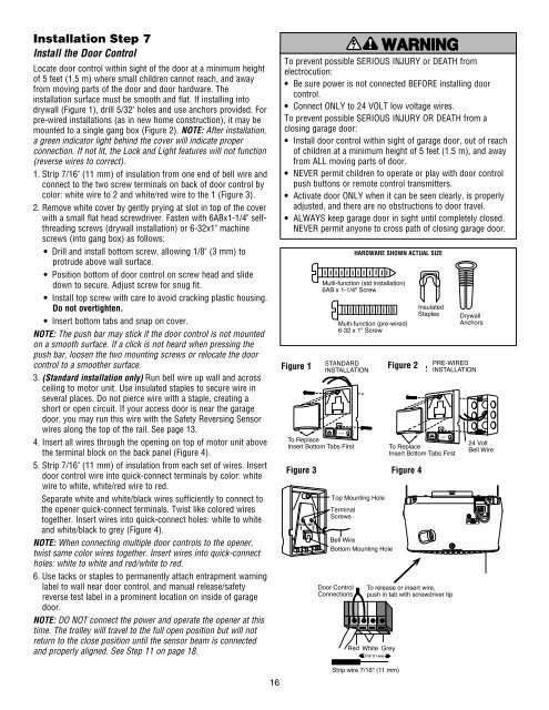
975KG31975KG31Installation Step 7Install the Door ControlLocate door control within sight of the door at a minimum heightof 5 feet (1.5 m) where small children cannot reach, and awayfrom moving parts of the door and door hardware. Theinstallation surface must be smooth and flat. If installing intodrywall (Figure 1), drill 5/32" holes and use anchors provided. Forpre-wired installations (as in new home construction), it may bemounted to a single gang box (Figure 2). NOTE: After installation,a green indicator light behind the cover will indicate properconnection. If not lit, the Lock and Light features will not function(reverse wires to correct).1. Strip 7/16" (11 mm) of insulation from one end of bell wire andconnect to the two screw terminals on back of door control bycolor: white wire to 2 and white/red wire to the 1 (Figure 3).2. Remove white cover by gently prying at slot in top of the coverwith a small flat head screwdriver. Fasten with 6ABx1-1/4" selfthreadingscrews (drywall installation) or 6-32x1" machinescrews (into gang box) as follows:• Drill and install bottom screw, allowing 1/8" (3 mm) toprotrude above wall surface.• Position bottom of door control on screw head and slidedown to secure. Adjust screw for snug fit.• Install top screw with care to avoid cracking plastic housing.Do not overtighten.• Insert bottom tabs and snap on cover.NOTE: The push bar may stick if the door control is not mountedon a smooth surface. If a click is not heard when pressing thepush bar, loosen the two mounting screws or relocate the doorcontrol to a smoother surface.3. (Standard installation only) Run bell wire up wall and acrossceiling to motor unit. Use insulated staples to secure wire inseveral places. Do not pierce wire with a staple, creating ashort or open circuit. If your access door is near the garagedoor, you may run this wire with the Safety Reversing Sensorwires along the top of the rail. See page 13.4. Insert all wires through the opening on top of motor unit abovethe terminal block on the back panel (Figure 4).5. Strip 7/16" (11 mm) of insulation from each set of wires. Insertdoor control wire into quick-connect terminals by color: whitewire to white, white/red wire to red.Separate white and white/black wires sufficiently to connect tothe opener quick-connect terminals. Twist like colored wirestogether. Insert wires into quick-connect holes: white to whiteand white/black to grey (Figure 4).NOTE: When connecting multiple door controls to the opener,twist same color wires together. Insert wires into quick-connectholes: white to white and red/white to red.6. Use tacks or staples to permanently attach entrapment warninglabel to wall near door control, and manual release/safetyreverse test label in a prominent location on inside of garagedoor.NOTE: DO NOT connect the power and operate the opener at thistime. The trolley will travel to the full open position but will notreturn to the close position until the sensor beam is connectedand properly aligned. See Step 11 on page 18.To prevent possible SERIOUS INJURY or DEATH fromelectrocution:• Be sure power is not connected BEFORE installing doorcontrol.• Connect ONLY to 24 VOLT low voltage wires.To prevent possible SERIOUS INJURY OR DEATH from aclosing garage door:• Install door control within sight of garage door, out of reachof children at a minimum height of 5 feet (1.5 m), and awayfrom ALL moving parts of door.• NEVER permit children to operate or play with door controlpush buttons or remote control transmitters.• Activate door ONLY when it can be seen clearly, is properlyadjusted, and there are no obstructions to door travel.• ALWAYS keep garage door in sight until completely closed.NEVER permit anyone to cross path of closing garage door.Figure Figure 1 1 STANDARDINSTALLATIONLOCKLIGHTTo ReplaceInsert Bottom Tabs FirstFigure 3Multi-function (std installation)6AB x 1-1/4" ScrewDoor ControlConnectionsHARDWARE SHOWN ACTUAL SIZEMulti-function (pre-wired)6-32 x 1" ScrewTop Mounting HoleTerminalScrewsBell WireBottom Mounting HoleTo release or insert wire,push in tab with screwdriver tipRed White Grey7/16" (11 mm)Figure Figure 2 2PRE-WIREDINSTALLATIONLOCKLIGHTTo ReplaceInsert Bottom Tabs FirstFigure 4InsulatedStaplesDrywallAnchors24 VoltBell Wire16Strip wire 7/16" (11 mm)