
Create successful ePaper yourself
Turn your PDF publications into a flip-book with our unique Google optimized e-Paper software.
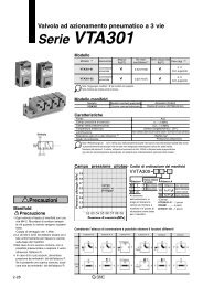
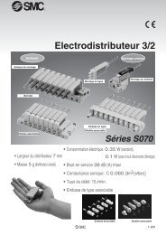
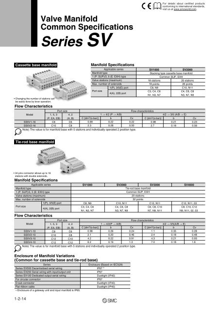
Valve ManifoldCommon Specifications<strong>Series</strong> <strong>SV</strong>For details about certified productsconforming to international standards,visit us at www.smcworld.com.Cassette base manifold• Changing the number of stations canbe easily done by lever operation.Flow CharacteristicsModelSS5V1-16SS5V2-161, 5, 3(P, EA, EB)C8C10Port size4, 2(A, B)C6C8C [dm 3 /(s·bar)]0.892.3Manifold SpecificationsApplicable seriesManifold type1 (P: SUP)/3, 5 (E: EXH) typeValve stations (maximum)Max. number of solenoids1(P), 3/5(E) portPort size4(A), 2(B) portNote) The value is for manifold base with 5 stations and individually operated 2 position type.<strong>SV</strong>1000<strong>SV</strong>2000Stacking type cassette base manifoldCommon SUP, EXH18 stations20 stations18 points26 pointsC8, N9C10, N11C3, C4, C6C4, C6, C8N1, N3, N7N3, N7, N9Flow characteristics1 4/2 (P A/B) 4/2 3/5 (A/B E)b0.220.28Cv0.220.50C [dm 3 /(s·bar)]0.982.7b0.210.18Cv0.230.56Tie-rod base manifold• 34 pins connector allows up to 16stations with double solenoids.Manifold SpecificationsApplicable seriesManifold type1 (P: SUP)/3, 5 (E: EXH) typeValve stations (maximum)Max. number of solenoids1(P), 3/5(E) portPort size4(A), 2(B) portFlow Characteristics<strong>SV</strong>1000C8, N9C3, C4, C6N1, N3, N7<strong>SV</strong>2000<strong>SV</strong>3000Tie-rod base manifoldCommon SUP, EXH20 stations32 pointsC10, N11C4, C6, C8N3, N7, N9C12, N11C6, C8, C10N7, N9, N11Port sizeFlow characteristicsModel1, 5, 3 4, 21 4/2(P A/B) 4/2 3/5(A/B E)SS5V1-10SS5V2-10SS5V3-10SS5V4-10(P, EA, EB)C8C10C12C12(A, B)C6C8C10C12C [dm 3 /(s·bar)]0.982.14.26.2b0.260.200.220.19Cv0.240.460.911.3C [dm 3 /(s·bar)]1.12.44.37.0b0.350.180.210.18Note) The value is for manifold base with 5 stations and individually operated 2 position type.<strong>SV</strong>4000C12, N11, 03C8, C10, C12N9, N11, 02, 03Cv0.280.480.931.6Enclosure of Manifold Variations(Common for cassette base and tie-rod base)<strong>Series</strong><strong>Series</strong> EX500 Decentralized serial wiring<strong>Series</strong> EX250 Serial wiring with input/output onit<strong>Series</strong> EX120 Dedicated output serial wiringFor circular connectorD-sub connectorFlat ribbon cable∗ Enclosure of a gateway unit and input manifold is IP65.1-2-14Enclosure (Based on IEC529)IP67 ∗IP67Dusttight (IP40)IP67Dusttight (IP40)Dusttight (IP40)
Decentralized Serial WiringIP67 compliant<strong>Series</strong> EX500<strong>SV</strong>SZSYSYJSXTie-rod baseCassette baseApplicable seriesCassette base manifold<strong>SV</strong>1000/<strong>SV</strong>2000Tie-rod base manifold<strong>SV</strong>1000/<strong>SV</strong>2000/<strong>SV</strong>3000/<strong>SV</strong>4000• Number of output points: 16 points• EX500 gateway unit communication specificationsRemote I/O, DeviceNet, PROFIBUS-DP1-2-17
<strong>Series</strong> EX500Decentralized Serial Wiring<strong>Series</strong> <strong>SV</strong>For details about certified productsconforming to international standards,visit us at www.smcworld.com. Tie-rod baseSS5V Cassette base<strong>Series</strong>1 <strong>SV</strong>10002 <strong>SV</strong>20003 <strong>SV</strong>30004 <strong>SV</strong>40001 W 10S A1WHow to OrderDSS5V 1 W 16S A1W D 05MountingNilD∗D0D3···D1605 UUDirect mountingDIN rail mounting (With DIN rail)DIN rail mounting (Without DIN rail)For 3 stations When a longer DIN rail is desiredthan the specified stations. (Specify aFor 16 stations longer rail than the standard length.)···∗ In the case ofD0, only DINrail fittings areattached.12Valve stationsSymbol02··· ···080216Stations2 stations··· ···8 stations2 stations16 stations<strong>Series</strong><strong>SV</strong>1000<strong>SV</strong>2000A1WA2W0NoteDouble wiringspecificationsEnclosureIP67 specificationsSI unit(2)Specified layout(up to 16 solenoids possible.)For Remote I/OFor DeviceNet/For ProfiBus-DPWithout SI unit(1)Note 1) Double wiring specifications: Single, double, 3 position and 4 position solenoidvalves can be used on all manifold stations. Use of a single solenoid will resultin an unused control signal. If this is not desired, order with a specified layout.Note 2) Specified layout: Indicate wiring specifications on the manifold specificationsheet. (Note that double, 3 position and 4 position valves cannot be usedwhere single solenoid wiring has been specified.)UDBDIN rail length specifiedNil Standard length3 For 3 stations (Specify a longer railthan the standard16 For 16 stations length.)······P, E port locationU side (2 to 10 stations)D side (2 to 10 stations)Both sides (2 to 16 stations)SUP/EXH block assembly specificationsNil∗SRRS∗Internal pilotInternal pilot/Built-in silencerExternal pilotExternal pilot/Built-in silencerNote) When the built-in silencer typeis used, keep the exhaust portfrom coming in direct contactwith water or other liquids.A, B port size (metric)Symbol A, B portC3C4C6C4C6C8C6One-touch fitting for ø3.2One-touch fitting for ø4One-touch fitting for ø6One-touch fitting for ø4One-touch fitting for ø6One-touch fitting for ø8One-touch fitting for ø6C8 One-touch fitting for ø8∗ In the case of mixedC10 One-touch fitting for ø10specifications (M), indicateseparately on the manifoldC8 One-touch fitting for ø8specification sheet. C10 One-touch fitting for ø10∗ Port sizes of X, PE port forexternal pilotC1202One-touch fitting for ø12Rc 1/4specifications (R, RS) are 03 Rc3/8ø4 (metric), ø5/32" (inch)02F G 1/4for <strong>SV</strong>1000/2000 and ø6(metric) and ø1/4" (inch)03F G 3/8for <strong>SV</strong>3000/4000.M A, B ports mixed1-2-20P, E port Applicable seriesOne-touchfitting for ø8One-touchfitting for ø10One-touchfitting ø12One-touchfitting ø12Rc 3/8G 3/8<strong>SV</strong>1000<strong>SV</strong>2000<strong>SV</strong>3000<strong>SV</strong>4000A, B port size (inch)SymbolN1N3N7N3N7N9N7N9N11N9N1102N03N02T03TMA, B portOne-touch fitting for ø1/8"One-touch fitting for ø5/32"One-touch fitting for ø1/4"One-touch fitting for ø5/32"One-touch fitting for ø1/4"One-touch fitting for ø5/16"One-touch fitting for ø1/4"One-touch fitting for ø5/16"One-touch fitting for ø3/8"One-touch fitting for ø5/16"One-touch fitting for ø3/8"NPT 1/4NPT 3/8NPTF 1/4NPTF 3/8A, B ports mixedP, E port Applicable seriesOne-touchfitting forø5/16"One-touchfitting forø3/8"One-touchfitting forø3/8"One-touchfitting for ø3/8"NPT 3/8NPTF 3/8<strong>SV</strong>1000<strong>SV</strong>2000<strong>SV</strong>3000<strong>SV</strong>4000
D side<strong>Series</strong> EX500Decentralized Serial Wiring<strong>Series</strong> <strong>SV</strong>How to Order Valve Manifold AssemblyOrdering example (<strong>SV</strong>1000)ManifoldSS5V1-W16SA1WD-06B-C6 (1 set)Double solenoid<strong>SV</strong>1200-5FU (2 sets)Single solenoid<strong>SV</strong>1100-5FU (4 sets)U sidePWR COMSS5V1-W16SA1WD-06B-C6······1 set (Manifold part no.)∗<strong>SV</strong>1100-5FU······4 sets (Single solenoid part no.)∗<strong>SV</strong>1200-5FU······2 sets (Double solenoid part no.)<strong>SV</strong>SZSYD D D D D DStationsSYJSX3 2 1How to Order Solenoid Valves<strong>SV</strong> 1 100 5 FNote)Note) Available with manifold blockfor station additions. Refer topages 1-2-89 and 1-2-93.<strong>Series</strong>1 <strong>SV</strong>10002 <strong>SV</strong>20003 <strong>SV</strong>30004 <strong>SV</strong>4000Manual overrideNil: Non-locking pushtypeD: Push-turn lockingslotted typeType of actuation12345AB2 position single solenoid2 position double solenoid3 position closed center3 position exhaust center3 position pressure center4 position dual 3 port valve: N.C./N.C.4 position dual 3 port valve: N.O./N.O.4 position dual 3 port valve: N.C./N.O.C∗ 4 position dual 3 port valves areapplicable to <strong>Series</strong> <strong>SV</strong>1000 and <strong>SV</strong>2000only.Pilot typeNil Internal pilotR External pilot∗ External pilot specificationsis not available for 4position dual 3 port valves.Back pressurecheck valveNil NoneK Built-in∗ Built-in back pressurecheck valve type isapplicable to series<strong>SV</strong>1000 only.∗ Back pressure checkvalve is not available for3 position closed centerand 3 position pressureRated voltage5 24 VDCLight/Surge voltage suppressorURWith light/surge voltage suppressorWith surge voltage suppressorRefer to Precautions 2on page 1-2-9.1-2-21
<strong>Series</strong> <strong>SV</strong>Dimensions: <strong>Series</strong> <strong>SV</strong>4000 for EX500 Decentralized Serial WiringUDB02,C8,N903,C10,N11C12, Tie-rod base manifold: SS5V4-W10SAWD- Stations (S, R, RS) - (-D) When P, E port outlets are indicated on the U side or D side, the P, E ports on the opposite side are plugged. External pilot port positions and silencer discharge port positions are the same as P, E port outlet positions.(Pitch)P = 24 24 48.625 11.8With External Pilot Specifications20 1114.535U side4-ø6.2(For mounting)E 3/5P 1One-touch fitting[1(P), 3/5(E) port]Applicable tubing O.D.: ø12ø3/8"One-touch fitting[4(A), 2(B) port]Applicable tubing O.D.: ø8, ø5/16"ø10, ø3/8"ø124AB 24AB 24AB 24AB 2Rc 1/4, 3/8[4(A), 2(B) port]L3L5(5.4)4AB 2E 3P 1C22-M12Rc 3/8[1(P), 3(E) port]C1D side(L4)40.463.9E 3/5P 1One-touch fitting[X: External pilot port]Applicable tubing O.D.: ø6ø1/4"XPE4AB 24AB 24AB 24AB 24AB 2E 3P 1One-touch fitting[PE: Pilot EXH port]Applicable tubing O.D.: ø6ø1/4"XPEC2C1DIN rail holding screw(For DIN rail mounting)BAA BBAA BBABABA13.3[For Rc 1/4, 3/8]PWR COML2(Rail mounting hole pitch: 12.5)L1(Station n) (Station 1)Light/Surge voltage suppressorSI unit16.285.561.879.413.730.135.858.374.8164.7148.298.256.329.6 17.585.53568.5 9.581.7 75Manual override(Press and turn for the locking type.)4(A) port side: Orange2(B) port side: GreenSilencer (Air discharge port)(Built-in silencer5 specifications)With option105.558.51Individual SUP3/5spacerIndividual EXHspacerE4A51 2 B 2 B 2 B 2 P 1P 13AE4A4A3/5EP6388.5107.5114.51Interface regulator<strong>SV</strong>4000-M1-114.7(For DIN rail mounting)(10)BABABInterface regulator<strong>SV</strong>4000-00-BA202.9172.9AAAABBABBMAX.20L DimensionL n 2L1L2L3L4L5173162.5145.613.51093198187.5169.6141334223212.5193.614.51575248237.5217.6151816273262.5241.615.52057298287.5265.6162298323312.5289.616.52539348337.5313.61727710373362.5337.617.530111385.5375361.61232512410.5400385.612.534913435.5425409.61337314460.5450433.613.539715485.5475457.614421n: Stations16510.5500481.614.54451-2-34
Dedicated Output Serial Wiring<strong>Series</strong> EX120<strong>SV</strong>SZSYSYJSXTie-rod baseCassette baseApplicable seriesCassette base manifold<strong>SV</strong>1000/<strong>SV</strong>2000Tie-rod base manifold<strong>SV</strong>1000/<strong>SV</strong>2000/<strong>SV</strong>3000/<strong>SV</strong>4000• Number of outputs points: 16 points1-2-43
<strong>Series</strong> EX120Dedicated Output Serial Wiring<strong>Series</strong> <strong>SV</strong>For details about certified productsconforming to international standards,visit us at www.smcworld.com. Tie-rod base Cassette baseSI unitCDEF1GHJ1J2KQR1R2UV<strong>Series</strong>1 <strong>SV</strong>10002 <strong>SV</strong>2000SS5V 1<strong>Series</strong>1 <strong>SV</strong>10002 <strong>SV</strong>20003 <strong>SV</strong>30004 <strong>SV</strong>4000How to OrderASS5V 1 16S3 A D 05Symbol Specifications0 Without SI unitA ∗ With general type SI unit (<strong>Series</strong> EX300)Mitsubishi Electric Corp.:BMELSECNET/MINI-S3 Data Link SystemOMRON Corp.: SYSBUS Wire SystemSHARP Corp.: Satellite I/O Link SystemMatsushita Electric Works: MEWNET-F SystemNKE Corp.: Uni-wire System (16 output points)∗ For the general purpose type, a transmissionunit is require on the CPU side.1-2-44Rockwell Automation:Allen Bradley Remote I/O (RIO) SystemNKE Corp.: Uni-wire H SystemSUNX Corp.: S-LINK System (16 output points)SUNX Corp.: S-LINK System (8 output points)Fuji Electric Co.: T-LINK Mini SystemDeviceNet, CompoBus/D (OMRON Corp.)OMRON Corp.: CompoBus/S System (16 output points)OMRON Corp.: CompoBus/S System (8 output points)JEMANET (JPCN-1)Mitsubishi Electric Corp.: CC-LINK SystemSI Unit Part No.Valve stationsSymbol StationsNote02 2 stations(1)Double wiring specifications08 8 stations02 2 stations(2)Specified layout16 16 stations (up to 16 solenoids possible.)• Since J2 and R2 type SI units have 8outputs note that up to 8 solenoids can beaccommodated.• This also includes the number of blankingplate assemblies.Note 1) Double wiring specifications: Single,double, 3 position and 4 positionsolenoid valves can be used on allmanifold stations. Use of a singlesolenoid will result in an unusedcontrol signal. If this is not desired,order with a specified layout.Note 2) Specified layout: Indicate wiringspecifications on the manifoldspecification sheet. (Note thatdouble and 3 position valvescannot be used where singlesolenoid wiring has been specified.)P, E port location··· ···10S3··· ···UDBD05 UUU side (2 to 10 stations)D side (2 to 10 stations)Both sides (2 to 16 stations)MountingNilD∗D0D3Direct mountingDIN rail mounting (With DIN rail)DIN rail mounting (Without DIN rail)For 3 stations When a longer DIN rail is desiredthan the specified stations. (Specify aD16 For 16 stations longer rail than the standard length.)DIN rail length specifiedNil Standard length3 For 3 stations (Specify a longer railthan the standard16 For 16 stations length.)······SUP/EXH block assemblyspecificationsNilSRRSInternal pilotInternal pilot/Built-in silencerExternal pilotExternal pilot/Built-in silencerSymbolA∗SpecificationsWith general type SI unit (<strong>Series</strong> EX300)For SS5V-S3EX320-S001SymbolHSpecificationsNKE Corp.: Uni-wire H SystemBMitsubishi Electric Corp.:J1 SUNX Corp.: S-LINK System (16 output points)EX120-SMB1MELSECNET/MINI-S3 Data Link SystemJ2 SUNX Corp.: S-LINK System (8 output points)CDEF1OMRON Corp.: SYSBUS Wire SystemSHARP Corp.: Satellite I/O Link SystemMatsushita Electric Works: MEWNET-F SystemNKE Corp.: Uni-wire System (16 output points)EX120-STA1EX120-SSH1EX120-SPA1EX120-SUW1KQR1R2Fuji Electric Co.: T-LINK Mini SystemDeviceNet, CompoBus/D (OMRON Corp.)OMRON Corp.: CompoBus/S System (16 output points)OMRON Corp.: CompoBus/S System (8 output points)GRockwell Automation:U JEMANET (JPCN-1)EX120-SAB1Allen Bradley Remote I/O (RIO) SystemV Mitsubishi Electric Corp.: CC-LINK System∗ For terminal LED descriptions for each SI unit and cable wiring, etc., refer to pages 1-2-46 to 1-2-48.······∗ In the case ofD0, only DINrail fittings areattached.For SS5V-S3EX120-SUH1EX120-SSL1EX120-SSL2EX120-SFU1EX120-SDN1EX120-SCS1EX120-SCS2EX120-SJN1EX120-SMJ1
<strong>Series</strong> EX120Dedicated Output Serial Wiring<strong>Series</strong> <strong>SV</strong>How to Order Valve Manifold AssemblyOrdering example (<strong>SV</strong>1000)ManifoldSS5V1-16S3AD-06B-C6 (1 set)Double solenoid<strong>SV</strong>1200-5FU (2 sets)Single solenoid<strong>SV</strong>1100-5FU (4 sets)U sideStationsD D D D D D3 2 1<strong>SV</strong> 1 100<strong>Series</strong>1 <strong>SV</strong>10002 <strong>SV</strong>20003 <strong>SV</strong>30004 <strong>SV</strong>4000Type of actuation1 2 position single solenoid2 2 position double solenoid3 3 position closed center4 3 position exhaust center5 3 position pressure centerA 4 position dual 3 port valve: N.C./N.C.B 4 position dual 3 port valve: N.O./N.O.C 4 position dual 3 port valve: N.C./N.O.∗ 4 position dual 3 port valves areapplicable to <strong>Series</strong> <strong>SV</strong>1000 and<strong>SV</strong>2000 only.D sidePilot typeNil Internal pilotR External pilot∗ External pilot specificationsis not available for 4position dual 3 port valves.How to Order Solenoid Valves–5SS5V1-16S3AD-06B-C6········1 set (manifold part no.)∗<strong>SV</strong>1100-5FU······4 sets (Single solenoid part no.)∗<strong>SV</strong>1200-5FU······2 sets (Double solenoid part no.)FRated voltage5 24 VDCBack pressure check valve–Note) Available with manifold blockfor station additions. Refer topages 1-2-89 and 1-2-93.Manual overrideNil: Non-locking pushtypeD: Push-turn lockingslotted typeLight/Surge voltage suppressorURWith light/surge voltage suppressorWith surge voltage suppressorNil NoneK Built-in∗ Built-in back pressure check valve type is applicable to <strong>Series</strong> <strong>SV</strong>1000 only.∗ Back pressure check valve is not available for 3 position closed center and3 position pressure center.Refer to Precautions 2 on page 1-2-9.Note)<strong>SV</strong>SZSYSYJSXA, B port size (Metric)Symbol A, B portC3 One-touch fitting for ø3.2C4 One-touch fitting for ø4C6 One-touch fitting for ø6C4 One-touch fitting for ø4C6 One-touch fitting for ø6C8 One-touch fitting for ø8C6 One-touch fitting for ø6C8 One-touch fitting for ø8C10 One-touch fitting for ø10C8 One-touch fitting for ø8C10 One-touch fitting for ø10C12 One-touch fitting for ø1202 Rc 1/403 Rc 3/802F G 1/403F G 3/8P, E port Applicable seriesOne-touchfitting for ø8One-touchfitting for ø10One-touchfitting for ø12One-touchfitting for ø12Rc 3/8G 3/8<strong>SV</strong>1000<strong>SV</strong>2000<strong>SV</strong>3000<strong>SV</strong>4000A, B port size (Inch)SymbolN1N3N7N3N7N9N7N9N11N9N1102N03N02T03TMA, B portOne-touch fitting for ø1/8"One-touch fitting for ø5/32"One-touch fitting for ø1/4"One-touch fitting for ø5/32"One-touch fitting for ø1/4"One-touch fitting for ø5/16"One-touch fitting for ø1/4"One-touch fitting for ø5/16"One-touch fitting for ø3/8"One-touch fitting for ø5/16"One-touch fitting for ø3/8"NPT 1/4NPT 3/8NPTF 1/4NPTF 3/8P, E port Applicable seriesOne-touchfitting for ø5/16"One-touchfitting for ø3/8"One-touchfitting for ø3/8"One-touchfitting for ø3/8"NPT 3/8NPTF 3/8A, B ports mixed<strong>SV</strong>1000<strong>SV</strong>2000<strong>SV</strong>3000<strong>SV</strong>4000MA, B ports mixed∗ In the case of mixed specifications (M), indicate separately on the manifold specification sheet.∗ Port sizes of X, PE port for external pilot specification (R, RS) are ø4 (metric), ø5/32" (inch) for <strong>SV</strong>1000/2000 andø6 (metric) and ø1/4" (inch) for <strong>SV</strong>3000/4000.1-2-45
<strong>Series</strong> <strong>SV</strong> The serial transmission system reduces wiring work, while minimizing wiring and saving space. Maximum 16 stations (Specify a model with more than 9 stations by means of the manifold specification sheet.)Type A<strong>Series</strong> EX300Type B Mitsubishi Electric CorporationMELSECNET/MINI-S3Data Link SystemSTATION NO.U sideStationsD D D D D D3 2 1D side Stations are counted from D side as the 1st. A maximum of 16 solenoids is possible(16 stations with single solenoids).ItemSpecificationsExternal power supply 24 VDC + 10%/– 5%A, B, D, E, F1, G, J1,Current consumption 0.1 AJ2, K, R1, R2, H, U, V(Internal unit)0.3 A C, QName of terminal block, LEDNote24 V 0 V S1 S2 SG R1 R2 FGLEDTRDRUN/ERRRUNERR TRDADDRESS NO.DescriptionON during data receptionBlinks for normal data reception,ON for abnormal• Connection to T unit PLC manufacturer’s I/Ocard enables serial transmission.EX300-TMB1···· for Mitsubishi Electric CorporationEX300-TTA1···· for OMRON CorporationEX300-TFU1···· for Fuji Electric Co., Ltd.EX300-T001····· General purpose∗ Each T unit has 32 control points.• No. of output points, 16 pointsLEDPOWERRUNRDSDERRPOWERRUNSD RD ERRx 10 x 124 V 0 V SDA SDB SG RDA RDB FGDescriptionON for power supply inputON for normal data trafficwith master unitON during data receptionON during data transmissionON for data reception error,OFF when normal• MELSECNET/MINI-S3 Data Link SystemMaster unit : AJ71PT32-S3AJ71T32-S3A1SJ71PT32-S3• No. of output points, 16 points, No. of stations.occupied, 2 stationsSI manifold solenoid valveT unit OB unit SI unit SI unit Master unitRemote I/O unitRemote I/O unitCable wiringS1S2SG24 V0 VS1S2R1R2SGFG24 V0 V∗S1S2R1R2SGFG24 V0 V∗S1S2R1R2SGFG24 V0 VSDASDBRDARDBSGFG∗SDASDBRDARDBSGFGSDASDBRDARDBSGFG∗ Ground either the reception side or the transmissionside of the shielding wire shield.∗ Ground either the reception side or the transmissionside of the shielding wire shield.Type COMRON CorporationSYSBUS Wire SystemType DSHARP CorporationSatellite I/O Link SystemType EMatsushita Electric Works, Ltd.MEWNET-F SystemName of terminal block, LEDLEDRUNT/RERRRUNT/RERR14632DIP SW.24 V 0 V + - + - FGDescriptionON when transmission is normal andPLC is in operation modeBlinks when transmission is normal,ON when transmission is abnormal.LEDPOWERRUNERRR.SETHOLDPOWERRUN ERR R.SET HOLDADDRESS NO.TERM.24 V 0 V L1 L2 SG L1 L2 FG 24 V 0 V + - FG + - FGDescriptionON when power supply is ONON when power is ON andslave unit operates normallyON for abnormal slave unit switch setting,abnormal communication, master unitPLC stopped and defective slave unitON for master unit control inputLEDPOWERCOMM.ALARMPOWERCOMM. ALARMSTASTION NO.TERM.x 10 x 1 OFF ONDescriptionON when power supply is ONBlinks during datatransmission/receptionON for unit abnormality, blinks forstation no. setting errorNote• SYSBUS Wire SystemMaster unit : Type C500-RM201Type C200H-RM201• No. of output points, 16 points• Satellite I/O Link SystemJW-23LM, JW-23LMHMaster unit : ZW-31LMJW-31LM, JW-31LMH• No. of output points, 16 points• MEWNET-F SystemMaster unit : AFP3740, AFP3742AFP5740, AFP5742• No. of output points, 16 pointsMaster unit SI unit SI unita) 2-wire typeWiring does not include signal ground line (SG).ZW-31LM Master unit Slave unit 01 Slave unit 03 Slave unit 75L1L1L1L1Master unitSI unitSI unitCable wiring+–+–+–FG24 V0 VType 3 ground+–+–FG24 V0 VType 3groundL2L2SGSGSHIELDSHIELDFGTwisted pair wirewith shieldL2L2SGSGSHIELDSHIELDType 3 groundType 3 ground Type 3 ground Type 3 groundb) 3-wire typeWiring does not include signal ground line (SG).ZW-31LM Master unit Slave unit 01 Slave unit 03 Slave unit 75L1L1L1L1L2L2L2L2SGSGSGSGSHIELDSHIELDSHIELDSHIELDFGTwisted pair wirewith shieldType 3 groundType 3 ground Type 3 ground Type 3 ground+–FG+–+–FG+–FG+–FG+–FG24 V0 V24 V0 VType 3 groundType 3ground1-2-46
<strong>Series</strong> EX120Dedicated Output Serial Wiring<strong>Series</strong> <strong>SV</strong>Type F1NKE CorporationUni-wire SystemType GRockwell Automation, Inc.Allen Bradley Remote I/O (RIO) SystemType J1, J2SUNX CorporationS-LINK SystemName of terminal block, LEDNoteLEDPOWERSENDPOWER24 V 0 V D G D G 24 V 0 V24 V 0 V L1 L2 SHILD L1 L2 FGG D 0 V 24 V G D 0 V 24 V• Uni-wire SystemSend unit : SD-120SENDADDRESSDescriptionON for power supply input(ON when normal, flickers when voltage drops)Transmission indication: Blinks when normal,OFF or ON when abnormal• No. of output points, 16 pointsONOFFLEDPOWERCOMERRORPOWERSENDDescriptionON when power supply is ONON when communication is normalBlinks when communication is initializedOFF for abnormal communicationON for abnormal communication• Remote I/O (RIO) SystemADDRESS• No. of output points, 16 pointsONOFFLEDPOWERSENDPOWER SENDDescriptionON for power supply inputTransmission indication: Blinks whennormal, Blinks slowly when abnormal• S-LINK SystemS-LINK controller: SL-CU1ADIP SW.• No. of output points, 16 points (Type J1)No. of output points, 8 points (Type J2)14632<strong>SV</strong>SZSYSYJSXCable wiringTransmission lineDGPowersupplyPowersupply24 V0 V24 V0 VPowersupply 24 V0 VPowersupply 24 V0 V24 V0 VDGDG24 V0 V24 V0 VDGDG24 V0 VMaster unitLINE1LINE2SHIELDSI unitL1L2SHIELDL1L2FG24 V0 VType 3 groundSI unitL1L2SHIELDL1L2FG24 V0 VType 3groundTerminalresistora) Type T branchingmulti-drop wiring(S-LINK System)BlackWhiteGMain transmissionlineD 0 V24 V GD0 V24 VBrownBlueCrimped connector SL-J1Ab) Crossover wiring(Sensor Link System)GD0V 24V GD0V 24VTransmission lineDGThe above is the example of using dedicated S-LINKflat ribbon cable SL-RCMl00.Type KFuji Electric Co., Ltd.T-LINK Mini SystemType QDeviceNetType R1, R2OMRON CorporationCompoBus/SSTATION NO.PWRMOD/NET1SETTINGSName of terminal block, LEDLEDLEDPOWERALMPOWER ALMTERM.x 10 x 1 ON OFF24V 0V S1 S2 SD S1 S2 FGDescriptionON for power supply inputON for abnormal transmissionor processor side power supply cutLEDPWRMOD/NET463224 V 0 V V- CANL FG CANH V+DescriptionGreen light ON for DeviceNet circuit power inputOFF When this unit is off line or circuit power is OFFGreen blinks When waiting for connection (On line)Green ON When connection is established (On line)RedblinksRedONWhen connection time out occurs(recoverable communication abnormality)For MAC ID duplication error, or BUSOFF error(major communication abnormality)LEDPWRCOMMERRPWRADDRESS NO.COMM ERR 14632BS+ BDH BDL BS- FG 24 V 0 VDescriptionON when communication power is supplied,OFF when power is OFFON for normal communication, OFF forabnormal communication or waitingON for abnormal communication, OFF fornormal communication or waitingNote• T-LINK Mini SystemMaster unit : FTM100BConverter : FRC100A-G02Repeater : FRC200A-C10• No. of output points, 16 points• DeviceNet• OMRON Corporation: CompoBus/D SystemMaster unit : Type C200HW-DRM21-V1Master unit : Type CS1W-DRM21• No. of output points, 16 points• CompoBus/S SystemMaster unit : Type C200HW-SRM21-V1Master unit : Type CQM1-SRM21-V1No. of output points, 16 points (Type SR1)• No. of output points, 8 points (Type SR2)24 V 0 V V– CANL FG CANH V + 24 V 0 V V– CANL FG CANH V +BS + BDH BDL BS– 24 V 0 V BS + BDH BDL BS– 24 V 0 VCable wiringMaster unit Slave unit 01 Slave unit 03 Slave unit 75S1S1S1S1S2S2S2S2SDSDSDSDFGFGFGFGTwisted pair wirewith shieldType 3 ground Type 3 ground Type 3 ground Type 3 groundConnect the shielding wire to the SD terminal. If the shielding wire isnot connected to the SD terminal, normal transmission will beimpossible even for short distances. Furthermore, do not ground theshielding wire (SD).V–CANLFGCANHV +MasterBDHBDLConnectorwith terminal resistorBranch crimped connectors1-2-47
ON12345678872387238723<strong>Series</strong> <strong>SV</strong>Type HNKE CorporationUni-wire H SystemType UJEMANET (JPCN-1)Type VMitsubishi Electric CorporationCC-LINK SystemName of terminal block, LEDLEDPOWERSENDPOWER SENDONOFFADDRESS24V 0V D G D G 24V 0VDescriptionON for power supply input(ON when normal, flickers when voltage drops)Transmission indication: Blinks when normal,OFF or ON when abnormalLEDPOWERCOMMALARMPOWERCOMMALARM24V 0V A B SG FG 24V 0VONDIP.SW14632DescriptionON for SI unit power supply inputOn for normal communicationON for abnormal communicationLEDPWL RUNSDRDL ERR.LERR.PWSDLRUNRDB RATE46329651496STATION NO.4632463224V 0V +24V 24G DA DB DG FG514DescriptionON when communication power issupplied, OFF when power is OFFON when normal data is being receivedON when data is transmittedON when data is receivedON for transmission error/wrong setting,Blinks when station or transmission speedsetting changes during operation965x 10 x 114Note• Uni-wire H SystemSend unit: SD-H2• No. of output points, 16 points• JEMANET (JPCN-1)(Reference)AJ71J92-S3 (Mitsubishi Electric Corporation)A1SJ71J92-S3 (Mitsubishi Electric Corporation)Type C200HW-JRM21 (OMRON Corporation)NJ-JPCN-1 (Fuji Electric Co., Ltd.)NP1L-JP1 (Fuji Electric Co., Ltd.)No. of output points, 16 points• CC-Link SystemMaster unit : AJ61BT11Master unit : A1SJ61BT11Master unit : AJ61QBT11Master unit : A1SJ61QBT11• No. of output points, 16 pointsDGa) 2-wire typeCable wiringTransmission linePowersupplyPowersupplyPowersupplyPowersupply24 V0 V24 V0 V24 V0 V24 V0 V24 V0 VDGDG24 V0 V24 V0 VDGDG24 V0 VMaster stationSGBAFGb) 3-wire typeMaster stationSGBAFGSlave unit(S1 unit)SG BAFGTwisted pair wirewith shieldSlave unit(S1 unit)SG BAFGTwisted pair wirewith shieldSlave unit(S1 unit)SG BAFGSlave unit(S1 unit)SG BAFGSlave unit(S1 unit)SG BAFGSlave unit(S1 unit)SG BAFGTerminalresistorMaster unit SI unit SI unitDADADADBDBDBDGDGDGSLDFGFGFGTwisted pair wirewith shieldType 3 groundType 3 groundTerminalresistorType 3 groundDG1-2-48
<strong>Series</strong> <strong>SV</strong>Dimensions: <strong>Series</strong> <strong>SV</strong>4000 for EX120 Dedicated Output Serial WiringUStations DB Tie-rod base manifold: SS5V4-10S3D- (S, R, RS) -02,C8,N9,03,C10,N11C12,(-D) When P, E port outlets are indicated on the U side or D side, the P, E ports on the opposite side are plugged. External pilot port positions and silencer discharge port positions are the same as P, E port outlet positions.2524(Pitch)P = 24With External Pilot Specifications20 1113.714.535One-touch fitting[1(P), 3/5(E) port]Applicable tubing O.D.: ø12ø3/8"One-touch fitting[4(A), 2(B) port]Applicable tubing O.D.: ø8, ø5/16"ø10, ø3/8"ø12U side4-ø6.2(For mounting)E 3/5P 14B 24 A 4 A 4 A 4 A 4 E 3/5E 3 A 4 A 4 A 4 A 4 AB 2B 2B 2B 2Rc 1/4, 3/8[4(A), 2(B) port]L3L5(5.4)P 116.535.8Rc 3/8[1(P), 3(E) port]28.8 (L4)D side58.374.8P 1XPEB 2B 2One-touch fitting[X: External pilot port]Applicable tubing O.D.: ø6ø1/4"B 2B 2AB 2E 3P 1XPEOne-touch fitting[PE: Pilot EXH port]Applicable tubing O.D.: ø6ø1/4"DIN rail holding screw(For DIN rail mounting)164.7148.298.256.329.6 17.5BAA BBAA BBABABA13.3[For Rc 1/4, 3/8]8355.56481.7 75M3TerminalscrewManual overridePress and turn for the( locking type. )4(A) port side: Orange2(B) port side: GreenL2(Rail mounting hole pitch: 12.5)L1(Station n) (Station 1)Light/Surge voltage suppressor52.26.2Silencer (Air discharge port)(Built-in silencer specifications)With option105.558.51Individual SUP spacerIndividual EXH spacer3/5 A 4 A 4 A A 4 E 3/551 2 B 2 B 2 B 2 P 1E 3 P 1EP6388.5107.5114.585.561.814.716.2(For DIN railmounting)(10) 81.71Interface regulator<strong>SV</strong>4000-M1-BB1BBInterface regulator<strong>SV</strong>4000-00-MAX.20202.9172.9AAAAAAAABBBBL DimensionL n 2L1L2L3L4L5185.517513212.51091-2-543210.5200156131334235.522518013.51575260.5250204141816285.527522814.52057310.5300252152298335.532527615.52539360.53503001627710385.537532416.530111410.54003481732512435.542537217.534913448437.539611.537314473462.54201239715498487.544412.5421n: Stations16523512.546813445Note) The width of type E (Matsushita Electric Works, Ltd.) and type G (Rockwell Automation, Inc.) SI units are 24.3 mm greater.For details, please contact <strong>SMC</strong>.
Circular ConnectorIP67 compliant<strong>SV</strong>SZSYSYJSXTie-rod baseCassette baseApplicable seriesCassette base manifold<strong>SV</strong>1000/<strong>SV</strong>2000Tie-rod base manifold<strong>SV</strong>1000/<strong>SV</strong>2000/<strong>SV</strong>3000/<strong>SV</strong>4000• Number of connectors: 26 pins1-2-55
For details about certified productsconforming to international standards,visit us at www.smcworld.com.Circular Connector<strong>Series</strong> <strong>SV</strong>1234 Tie-rod baseSS5V Cassette base1-2-5612<strong>Series</strong><strong>SV</strong>1000<strong>SV</strong>2000<strong>SV</strong>3000<strong>SV</strong>4000<strong>Series</strong><strong>SV</strong>1000<strong>SV</strong>20001WSS5V 1 W 16CD 05Valve stationsType 16: <strong>Series</strong> <strong>SV</strong>1000Symbol02··· ···0902Stations2 stations··· ···9 stations2 stationsEnclosureIP67 specificationsNoteDouble wiring specifications (1)Specified layout (2)(up to 18 solenoids possible.)18 18 stationsType 16: <strong>Series</strong> <strong>SV</strong>2000Symbol StationsNote02 2 stations··· ···120220UDBHow to OrderDouble wiring specifications (1)12 stations2 stationsSpecified layout (2)20 stations (up to 24 solenoids possible.)Note 1) Double wiring specifications: Single, double,3 position and 4 position solenoid valvescan be used at all of the manifold stations.Use of a single solenoid will result in anunused control signal. If this is not desired,order with a specified layout.Note 2) Specified layout: Indicate wiringspecifications on the manifold specificationsheet. (Note that double, 3 and 4 positionvalves cannot be used where singlesolenoid wiring has been specified.)··· ···P, E port locationU side (2 to 10 stations)D side (2 to 10 stations)Both sides (2 to 20 stations)SUP/EXH block assembly specificationsNil∗SRRS∗Symbol02··· ···20Stations2 stations··· ···12 12 stations02 2 stations20 stationsValve stationsNote(1)Double wiringspecifications(2)Specified layout(Up to 24 solenoids possible.)10CDInternal pilotInternal pilot/Built-in silencerExternal pilotExternal pilot/Built-in silencer05 UUNote) When the built-in silencer type is used, keep theexhaust port from coming in direct contact withwater or other liquids.Note 1) Double wiring specifications: Single, double, 3 position and 4 positionsolenoid valves can be used at all of the manifold stations. Use of asingle solenoid will result in an unused control signal. If this is notdesired, order with a specified layout.Note 2) Specified layout: Indicate wiring specifications on the manifoldspecification sheet. (Note that double, 3 and 4 position valves cannotbe used where single solenoid wiring has been specified.)···MountingNilD∗D0D3···D20Direct mountingDIN rail mounting (With DIN rail)DIN rail mounting (Without DIN rail)For 3 stations When a longer DIN rail is desiredthan the specified stations.(Specify a longer rail than theFor 20 stations standard length.)∗ In the case of D0, only DIN railfittings are attached.······DIN rail length specifiedNilStandard length3 For 3 stations(Specify a longer rail than thestandard length.)20Note) For 20 stationsNote) Able to specify the length for 3stations up to 18 stations for<strong>SV</strong>1000, which is available with 18station at the maximum.A, B port size (Metric)Symbol Specifications P, E port Applicable seriesC3 One-touch fitting for ø3.2One-touchC4 One-touch fitting for ø4fitting for ø8C6 One-touch fitting for ø6<strong>SV</strong>1000C4 One-touch fitting for ø4One-touchC6 One-touch fitting for ø6fitting for ø10C8 One-touch fitting for ø8<strong>SV</strong>2000C6 One-touch fitting for ø6One-touchC8 One-touch fitting for ø8fitting for ø12C10 One-touch fitting for ø10<strong>SV</strong>3000C8 One-touch fitting for ø8One-touchC10 One-touch fitting for ø10fitting for ø12C12 One-touch fitting for ø1202 Rc 1/4<strong>SV</strong>4000Rc 3/803 Rc 3/802F G 1/403F G 3/8G 3/8MA, B ports mixedA, B port size (Inch)Symbol Specifications P, E port Applicable seriesN1 One-touch fitting for ø1/8"One-touchN3 One-touch fitting for ø5/32"<strong>SV</strong>1000fitting for ø5/16"N7 One-touch fitting for ø1/4"N3 One-touch fitting for ø5/32"One-touchN7 One-touch fitting for ø1/4"<strong>SV</strong>2000fitting for ø3/8"N9 One-touch fitting for ø5/16"N7 One-touch fitting for ø1/4"One-touchN9 One-touch fitting for ø5/16"<strong>SV</strong>3000fitting for ø3/8"N11 One-touch fitting for ø3/8"N9 One-touch fitting for ø5/16" One-touchN11 One-touch fitting for ø3/8" fitting for ø3/8"02N NPT 1/4NPT 3/8 <strong>SV</strong>400003N NPT 3/802T NPTF 1/4NPTF 3/803T NPTF 3/8MA, B ports mixed∗ In the case of mixed specifications (M), indicate separately on themanifold specification sheet.∗ Port sizes of X, PE port for external pilot specification (R, RS) areø4(metric), ø5/32"(inch) for <strong>SV</strong>1000/2000 and ø6 (metric) andø1/4"(inch) for <strong>SV</strong>3000/4000.
D sideCircular Connector <strong>Series</strong> <strong>SV</strong>How to Order Valve Manifold AssemblyOrdering example (<strong>SV</strong>1000)ManifoldSS5V1-W16CD-06B-C6 (1 set)Double solenoid<strong>SV</strong>1200-5FU (2 sets)U sideStationsD D D D D DSingle solenoid<strong>SV</strong>1100-5FU (4 sets)SS5V1-W16CD-06B-C6··········1 set (manifold part no.)∗ <strong>SV</strong>1100-5FU······4 sets (Single solenoid part no.)∗ <strong>SV</strong>1200-5FU······2 sets (Double solenoid part no.)<strong>SV</strong>SZSYSYJSX3 2 1How to Order Solenoid Valves<strong>SV</strong> 1 100 – 5 F–Note)Note) Available with manifold blockfor station additions. Refer topages 1-2-89 and 1-2-93.<strong>Series</strong>1 <strong>SV</strong>10002 <strong>SV</strong>20003 <strong>SV</strong>30004 <strong>SV</strong>4000Manual overrideNil: Non-locking pushtypeD: Push-turn lockingslotted typeType of actuation1 2 position single solenoid2 2 position double solenoid33 position closed center4 3 position exhaust center5 3 position pressure centerA 4 position dual 3 port valve: N.C./N.C.B 4 position dual 3 port valve: N.O./N.O.C 4 position dual 3 port valve: N.C./N.O.∗ 4 position dual 3 port valves areapplicable to <strong>Series</strong> <strong>SV</strong>1000 and <strong>SV</strong>2000only.NilRPilot typeInternal pilotExternal pilot∗ External pilot specificationsis not available for 4position dual 3 port valves.Back pressurecheck valveNil NoneK Built-in∗ Built-in back pressure check valve typeis applicable to series <strong>SV</strong>1000 only.∗ Back pressure check valve is notavailable for 3 position closed centerand 3 position pressure center.Rated voltage5624 VDC12 VDCLight/Surge voltage suppressorURWith light/surge voltage suppressorWith surge voltage suppressorRefer to Precautions 2 on page 1-2-9.1-2-57
<strong>Series</strong> <strong>SV</strong>Manifold Electrical Wiring10C/16C Circular Connector Type (26 pins)@6@5CommonCommon!5 q!4!6w!3 @4 !7 e!2 @3 @5 !8 r!1 @2 @6 !9 t!0@1 @0yo i uLight/Surge voltagesuppressorLight/Surge voltagesuppressorLight/Surge voltagesuppressorLight/Surge voltagesuppressor@4@3@2@1rewqSOL.BSOL.ASOL.BSOL.ASOL.BSOL.ASOL.BSOL.AStation 12Station 11Station 2Station 1• This circuit has double wiring specifications for up to 12 stations. Since the usable number ofsolenoids differs depending on the manifold type, refer to the table below. In the case of singlesolenoids, connect to SOL. A. Furthermore, when wiring is specified on a manifoldspecification sheet, connections are made without skipping any connectors, and connectionsare made without skipping any connectors, and signals A for single and A, B for double are inorder 1 2 3 4, etc.• Stations are counted from D side (connector side) as the 1st.• Since solenoid valves do not have polarity, either the +COM or –COM can be used.Usable No. of SolenoidsModelTie-rod base type 10Cassette base type 16<strong>SV</strong>1000to<strong>SV</strong>4000<strong>SV</strong>1000<strong>SV</strong>2000Max. no. of solenoids2418241-2-58
987645<strong>Series</strong> <strong>SV</strong>Dimensions: <strong>Series</strong> <strong>SV</strong>4000 for Circular ConnectorUStations DB Tie-rod base manifold: SS5V4-W10CD- (S, R, RS) -25(Pitch)P = 24 2402,C8,N9,03,C10,N11,C12,(-D) When P, E port outlets are indicated on the U side or D side, the P, E ports on the opposite side are plugged. External pilot port positions and silencer discharge port positions are the same as P, E port outlet positions.65.8With External Pilot Specifications20113514.5One-touch fitting[1(P), 3/5(E) port]Applicable tubing O.D.: ø12ø3/8"One-touch fitting[4(A), 2(B) port]Applicable tubing O.D.: ø8, ø5/16"ø10, ø3/8"ø12U side4-ø6.2(For mounting)E 3/5P 14B 2E 3 A 4 A 4 A 4 A 4 AB 2B 2L5B 2L3(5.4)B 2P 1Rc 3/8[1(P), 3(E) port]Rc 1/4, 3/8[4(A), 2(B) port]47.313.7(L4)35.8D side74.858.3E 3/5P 1XPEOne-touch fitting[X: External pilot port]Applicable tubing O.D.: ø6ø1/4"4B 2Notch(To align connector position)E 3 A 4 A 4 A 4 A 4 AB 2B 2B 2B 2P 1One-touch fitting[PE: Pilot EXH port]Applicable tubing O.D.: ø6ø1/4"XPEDIN rail holding screw(For DIN rail mounting)164.7148.2BBBBB13.3[For Rc 1/4, 3/8]85.57598.256.317.529.6AA BAA BAManual overridePress and turn for the( locking type. )4(A) port side: Orange2(B) port side: GreenL2(Rail mounting hole pitch: 12.5)L1AA53581.758.912.2Silencer (Air discharge port)(Built-in silencerspecifications)114 15 213 2416 17 3 2512 23 1811 22 26 1910 21 2033.8With option3/5E4A41.6A4A4A3/5E(Station n) (Station 1)Light/Surge voltage suppressor105.558.5Individual SUP spacer1P2P 1B325EB2B21P6388.5107.5114.585.561.814.716.2(For DIN rail mounting)(10)(Cable assembly)Min. bending radius20 mm(84.5)(When circular connector is mounted)1Interface regulator<strong>SV</strong>4000-M1-BABA1BABA202.9172.9AAAABBBBIndividual EXH spacerInterface regulator<strong>SV</strong>4000-00-MAX.20L DimensionL n 2L1L2L3L4L5198187.5162.817.51093210.5200186.8121334235.5225210.812.51575260.5250234.8131816285.5275258.813.52057310.5300282.8142298335.5325306.814.52539360.5350330.81527710385.5375354.815.530111410.5400378.81632512435.5425402.816.534913460.5450426.81737314485.5475450.817.539715498487.5474.811.542116523512.5498.81244517548537.5522.812.546918573562.5546.81349319598587.5570.813.5517n: Stations20623612.5594.8145411-2-64
D-sub Connector<strong>SV</strong>SZSYSYJSXTie-rod baseCassette baseApplicable seriesCassette base manifold<strong>SV</strong>1000/<strong>SV</strong>2000Tie-rod base manifold<strong>SV</strong>1000/<strong>SV</strong>2000/<strong>SV</strong>3000/<strong>SV</strong>4000• Number of connectors: 25 pins• MIL-C-24308Conforming to JIS-X-51011-2-65
For details about certified productsconforming to international standards,visit us at www.smcworld.com. Tie-rod base Cassette baseValve stations<strong>Series</strong> <strong>SV</strong>1000Symbol02··· ···090218<strong>Series</strong> <strong>SV</strong>2000Symbol02··· ···20Stations2 stations··· ···9 stations2 stations18 stationsStations2 stations··· ···11 11 stations02 2 stations20 stations1-2-66<strong>Series</strong>1 <strong>SV</strong>10002 <strong>SV</strong>2000D-sub Connector<strong>Series</strong> <strong>SV</strong><strong>Series</strong>1 <strong>SV</strong>10002 <strong>SV</strong>20003 <strong>SV</strong>30004 <strong>SV</strong>4000SS5V 1–10FD 1How to OrderValve stationsSymbol0220Stations2 stations11 11 stations02 2 stations20 stationsSS5V 1– 16FD 1– 05 U – –Note(1)Double wiringspecificationsSpecified layout (2)(Up to 18 solenoidspossible.)Note(1)Double wiringspecifications(2)Specified layout(Up to 23 solenoidspossible.)Connector entry direction1 Upward2 LateralPilot typeNote(1)Double wiringspecifications(2)Specified layout(Up to 23 solenoidspossible.)Note 1) Double wiring specifications: Single, double,3 position and 4 position solenoidvalves can be used at all of the manifoldstations.Use of a single solenoid will result in anunused control signal in an unusedcontrol signal. If this is not desired, orderwith a specified layout.Note 2) Specified layout: Indicate wiring specificationson the manifold specification sheet.(Note that double, 3 and 4 position valvescannot be used where single solenoid wiringhas been specified.)P, E port locationUDBNilSRRS··· ···A, B port size (metric)Symbol A, B portC3 One-touch fitting for ø3.2C4 One-touch fitting for ø4C6 One-touch fitting for ø6C4 One-touch fitting for ø4C6 One-touch fitting for ø6C8 One-touch fitting for ø8C6 One-touch fitting for ø6C8 One-touch fitting for ø8C10 One-touch fitting for ø10C8 One-touch fitting for ø8C10 One-touch fitting for ø10C12 One-touch fitting for ø1202 Rc 1/403 Rc 3/802F G 1/403F G 3/8M··· ···– – –05 UU side (2 to 10 stations)D side (2 to 10 stations)Both sides (2 to 20 stations)Internal pilotInternal pilot/Built-in silencerExternal pilotExternal pilot/Built-in silencerP, E port Applicable seriesOne-touchfitting for ø8One-touchfitting for ø10One-touchfitting for ø12One-touchfitting for ø12Rc 3/8G 3/8A, B ports mixed<strong>SV</strong>1000<strong>SV</strong>2000<strong>SV</strong>3000<strong>SV</strong>4000Note 1) Double wiring specifications: Single, double,3 position and 4 position solenoid valvescan be used at all of the manifold stations.Use of a single solenoid will result in anunused control signal in an unusedcontrol signal. If this is not desired, orderwith a specified layout.Note 2) Specified layout: Indicate wiring specificationson the manifold specification sheet.(Note that double, 3 and 4 position valvescannot be used where single solenoidwiring has been specified.)MountingDIN rail length specifiedNil Standard length3 For 3 stations (Specify a longer railthan the standard20 Note) For 20 stations length.)Note) Able to specify the lengthfor 3 stations up to 18stations for <strong>SV</strong>1000, whichis available with 18stations at the maximum.···NilDD0D3···∗D20Direct mountingDIN rail mounting (With DIN rail)DIN rail mounting (Without DIN rail)For 3stationsFor 20stations···A, B port size (inch)Symbol A, B portN1 One-touch fitting for ø1/8"N3 One-touch fitting for ø5/32"N7 One-touch fitting for ø1/4"N3 One-touch fitting for ø5/32"N7 One-touch fitting for ø1/4"N9 One-touch fitting for ø5/16"N7 One-touch fitting for ø1/4"N9 One-touch fitting for ø5/16"N11 One-touch fitting for ø3/8"N9 One-touch fitting for ø5/16"N11 One-touch fitting for ø3/8"02N NPT 1/403N NPT 3/802T NPTF 1/403T NPTF 3/8M···P, E port Applicable seriesOne-touchfitting for ø5/16"One-touchfitting for ø3/8"One-touchfitting for ø3/8"One-touchfitting for ø3/8"NPT 3/8NPTF 3/8When a longerDIN rail isdesired than thespecifiedstations. (Specifya longer rail thanthe standard∗ In case of D0, only DINrail fittings are attached.A, B ports mixed∗ In the case of mixed specifications (M), indicate separately on the manifold specification sheet.∗ Port sizes of X, PE port for external pilot specifications (R, RS) are ø4 (metric), ø5/32" (inch) for <strong>SV</strong>1000/2000 and ø6(metric) and ø1/4" (inch) for <strong>SV</strong>3000/4000.<strong>SV</strong>1000<strong>SV</strong>2000<strong>SV</strong>3000<strong>SV</strong>4000
D sideD-sub Connector <strong>Series</strong> <strong>SV</strong>How to Order Valve Manifold AssemblyOrdering example (<strong>SV</strong>1000)ManifoldSS5V1-16FD1-06B-C6 (1 set)Double solenoid<strong>SV</strong>1200-5FU (2 sets)Single solenoid<strong>SV</strong>1100-5FU (4 sets)U sideSS5V1-16FD1-06B-C6··········1 set (manifold part no.)∗<strong>SV</strong>1100-5FU······4 sets (Single solenoid part no.)∗<strong>SV</strong>1200-5FU······2 sets (Double solenoid part no.)<strong>SV</strong>SZSYD D3DDDDSYJSXStations 12How to Order Solenoid Valves<strong>SV</strong> 1 100 – 5 F –Note)Note) Available with manifold blockfor station additions. Refer topages 1-2-89 and 1-2-93.<strong>Series</strong>1 <strong>SV</strong>10002 <strong>SV</strong>20003 <strong>SV</strong>30004 <strong>SV</strong>4000Manual overrideNil: Non-locking pushtypeD: Push-turn lockingslotted typeType of actuation1 2 position single solenoid2 2 position double solenoid33 position closed center4 3 position exhaust center5 3 position pressure centerA 4 position dual 3 port valve: N.C./N.C.B 4 position dual 3 port valve: N.O./N.O.C 4 position dual 3 port valve: N.C./N.O.∗ 4 position dual 3 port valves are applicableto <strong>Series</strong> <strong>SV</strong>1000 and <strong>SV</strong>2000 only.Pilot typeNil Internal pilotR External pilot∗ External pilot specificationsis not available for 4position dual 3 port valves.Rated voltage5624 VDC12 VDCLight/Surge voltage suppressorURWith light/surge voltage suppressorWith surge voltage suppressorBack pressure check valveNil NoneK Built-in∗ Built-in back pressure check valve type isapplicable to series <strong>SV</strong>1000 only.∗ Back pressure check valve is not available for 3position closed center and 3 position pressurecenter.Refer to Precautions 2 on page 1-2-9.1-2-67
<strong>Series</strong> <strong>SV</strong>Manifold Electrical Wiring10F/16F D-sub Connector Type (25 pins)Light/Surge voltagesuppressorLight/Surge voltagesuppressor1312112524CommonCommonSOL.BStation 11SOL.ALight/Surge voltagesuppressor21514SOL.BSOL.AStation 2Light/Surge voltagesuppressor1SOL.BStation 1SOL.A• This circuit has double wiring specifications for up to 11 stations. Since the usable number ofsolenoids differs depending on the manifold type, refer to the table below.In the case of single solenoids, connect to SOL.A. Furthermore, when wiring is specified on themanifold specification sheet, connections are made without skipping any connectors, and signalsA for single and A, B for double are in order 1 14 2 15, etc.• Stations are counted from D side (connector side) as the 1st.• Since solenoid valves do not have polarity, either the +COM or –COM can be used.Usable No. of SolenoidsModelTie-rod base type 10Cassette base type 16<strong>SV</strong>1000to<strong>SV</strong>4000<strong>SV</strong>1000<strong>SV</strong>2000Max. no. ofsolenoids2318231-2-68
P 1ABABABABD-sub Connector <strong>Series</strong> <strong>SV</strong>Dimensions: <strong>Series</strong> <strong>SV</strong>1000 for D-sub Connector12UStations DB Tie-rod base manifold: SS5V4-10FD - (S, R, RS) -C3, N1C4, N3C6, N7(-D) When P, E port outlets are indicated on the U side or D side, the P, E ports on the opposite side are plugged. External pilot port positions and silencer discharge port positions are the same as P, E port outlet positions.One-touch fitting[1(P), 3/5(E) port]Applicable tubing O.D.: ø8ø5/16"DIN rail holding screw(For DIN rail mounting)92.2834.683.710234-ø4.3(For mounting)3/5Light/Surge voltage suppressor59.545.5U side29.6 10.839.618.31EPABBA BA(Pitch)P = 10.542ABBA BA42ABBAL2 5(Rail mounting hole pitch: 12.5)L1(Station n) (Station 1)42ABBA42L3L5AB(C6:3.2)(N7:7)13.5Manual overridePress and turn for thelocking type.4(A) port side: Orange2(B) port side: Green( )BA42E 3/5E 3/5E 3/51P34.8 (6)(Lateral connector entry)One-touch fitting[4(A), 2(B) port]Applicable tubing O.D.: ø3.2, ø1/8"ø4, ø5/32"ø6, ø1/4"(L4) D side22(4.9)7.951.5 8.65.524.635(37.6)8Equivalent to applicable D-sub connector8.9 58.992.6Connector caseRelease lever(Both sides)Silencer (Air discharge port)(Built-in silencer specifications)With External Pilot Specifications4356.5One-touch fitting[X: External pilot port]Applicable tubing O.D.: ø42-M2.62-4-40 UNC[4(A), 2(B) with inch size ports]74.514.1 8.41XPPEJIS-X-5101{ MIL-C-24308 }With option37.5Individual EXH spacerIndividual SUP spacerAB42ABA 4B 2ø5/32"A 4B 2A 4B 2421XPPEOne-touch fitting[PE: Pilot EXH port]Applicable tubing O.D.: ø4ø5/32"4 A4 A4 A4 A3/5 E 3/52 B2 BP 1 E 32 B2 BInterface regulator<strong>SV</strong>100-06-EP 138.560.774Interface regulator<strong>SV</strong>100-05-MAX.14<strong>SV</strong>SZSYSYJSX11.8(For DIN railmounting)(7.5)1090(C6:3.2)(N7:7)BABABABA91.9100.4102.9111.4109.5118Dimensions are the ones for <strong>SV</strong>1300--.L DimensionL n 2L1L2L3L4L5123112.590.519.5633135.512510120.573.54148137.5111.521.5845160.515012222.594.56173162.5132.523.51057173162.514318115.58185.5175153.5191269198187.516420136.510210.5200174.52114711223212.518522157.512235.5225195.52316813235.522520618178.914248237.5216.51918915260.525022720199.516273262.5237.52121017285.527524822220.518298287.5258.52323119310.530026924241.5n: Stations20310.5300279.518.52521-2-71
<strong>Series</strong> <strong>SV</strong>Dimensions: <strong>Series</strong> <strong>SV</strong>4000 for D-sub Connector12UStations DB Tie-rod base manifold: SS5V4-10FD - (S, R, RS) -02,C8,N903,C10,N11C12,(-D) When P, E port outlets are indicated on the U side or D side, the P, E ports on the opposite side are plugged. External pilot port positions and silencer discharge port positions are the same as P, E port outlet positions.(Pitch)25 P = 24 24 40 (6)With External Pilot Specifications20 113514.5One-touch fitting[1(P), 3/5(E) port]Applicable tubing O.D.: ø12ø3/8"One-touch fitting[4(A), 2(B) port]Applicable tubing O.D.: ø8, ø5/16"ø10, ø3/8"ø12U side4-ø6.2(For mounting)E 3/5P 14B 24 A 4 A 4 A 4 A 4 E 3/5E 3 A 4 A 4 A 4 A 4 AB 2B 2B 2B 2P 135.8(43.9)(Lateral connector entry)Rc 3/8[1(P), 3(E) port]Rc 1/4, 3/8[4(A), 2(B) port]74.858.3One-touch fitting[X: External pilot port]Applicable tubing O.D.: ø6ø1/4"D sideSilencer (Air discharge port)(Built-in silencer specifications)P 1XPEB 2B 2B 2B 2E 3P 1One-touch fitting[PE: Pilot EXH port]Applicable tubing O.D.: ø6ø1/4"AB 2XPEDIN rail holding screw(For DIN rail mounting)164.7148.2Light/Surge voltage suppressorBABAManual overridePress and turn for the( locking type. )4(A) port side: Orange2(B) port side: GreenL2(Rail mounting hole pitch: 12.5)L1(Station n) (Station 1)BABABA2-M2.62-4-40 UNC[4(A), 2(B) with inchsize ports]Connector caseRelease lever (Both sides)Equivalent to applicable D-sub connector(For DIN railmounting)(10)16.213.7L3L5 21.5(5.4)(L4)98.256.329.6 17.5A BA B7.913.3[For Rc 1/4, 3/8]85.553512.2 58.981.7 75With option105.558.5{ }JIS-X-5101MIL-C-243083/5Individual SUP spacerIndividual EXH spacerE4A51 2 B 2 B 2 B 2 P 1P 13AE4A4A3/5E85.561.857.81Interface regulator<strong>SV</strong>4000-M1-1AB14.7BBBBP6388.5107.5114.5Interface regulator<strong>SV</strong>4000-00-202.9172.9AAAAAAABBBMAX.20L DimensionL n 2L1L2L3L4L5173162.5137211093198187.516121.51334223212.5185221575248237.520922.51816273262.5233232057298287.525723.52298310.5300281182539335.532530518.527710360.53503291930111385.537535319.532512410.54003772034913435.542540120.537314460.54504252139715485.547544921.542116510.55004732244517535.552549722.546918560.55505212349319585.557554523.5517n: Stations20610.5600569245411-2-74
Flat Ribbon Cable Connector<strong>SV</strong>SZSYSYJSXTie-rod baseCassette baseApplicable seriesCassette base manifold<strong>SV</strong>1000/<strong>SV</strong>2000Tie-rod base manifold<strong>SV</strong>1000/<strong>SV</strong>2000/<strong>SV</strong>3000/<strong>SV</strong>4000• Number of connectors: 26, 20, 10 pins• With strain reliefConforming to MIL-C-835031-2-75
For details about certified productsconforming to international standards,visit us at www.smcworld.com.Flat Ribbon Cable Connector<strong>Series</strong> <strong>SV</strong>Connector typePPGPH Tie-rod base<strong>Series</strong>1 <strong>SV</strong>10002 <strong>SV</strong>20003 <strong>SV</strong>30004 <strong>SV</strong>4000 Cassette baseFlat ribbon cable connector: 26 pinsFlat ribbon cable connector: 20 pinsFlat ribbon cable connector: 10 pinsSS5V 1–10 P D<strong>Series</strong>1 <strong>SV</strong>10002 <strong>SV</strong>2000Valve stations<strong>Series</strong> <strong>SV</strong>1000P: Flat ribbon cable 26 pins02··· ···09022 stations··· ···9 stations2 stationsHow to OrderSS5V 1– 16 P D 1– 05 U – –(1)Double wiringspecificationsSpecified layout (2)(Up to 18 solenoids possible.)Connectorentry direction12UpwardLateral1P, E port locationUDBNilSRRS– – –05 UU side (2 to 10 stations)D side (2 to 10 stations)Both sides (2 to 20 stations)Pilot typePH: Flat ribbon cable 10 pins0204022 stations4 stations2 stationsDouble wiring (1)specificationsSpecified layout (2)(Up to 8 solenoids possible.)··· ···18 18 stations08PG: Flat ribbon cable 20 pins02 2 stations(1)Double wiringspecifications··· ···090218··· ···9 stations2 stations18 stations(2)Specified layout(Up to 18 solenoids possible.)··· ···8 stationsValve stationsP: Flat ribbon cable 26 pins PH: Flat ribbon cable 10 pins0212022 stations12 stations2 stations(1)Double wiringspecifications(2)Specified layout0204022 stations4 stations2 stations(1)Double wiringspecifications(2)Specified layout20(Ip to 24 solenoids possible.)(Up to 8 solenoids possible.)20 stations08 8 stationsPG: Flat ribbon cable 20 pins02 2 stations(1)Double wiring09 9 stationsspecifications02 2 stations(2)Specified layout18 18 stations(Up to 18 solenoids possible.)··· ······ ······ ······ ···Internal pilotInternal pilot/Built-in silencerExternal pilotExternal pilot/Built-in silencer<strong>Series</strong> <strong>SV</strong>2000··· ······ ···DIN rail length specifiedNil Standard length3 For 3 stations (Specify a longerrail than the20Note) For 20 stations standard length.)Note) Able to specify thelength for 3 stations upto 18 stations for<strong>SV</strong>1000, which isavailable with 18stations at themaximum.P: Flat ribbon cable 26 pins PH: Flat ribbon cable 10 pins02 2 stations(1) 02 2 stations(1)Double wiringDouble wiring120212 stations2 stationsspecificationsSpecified layout (2)04024 stations2 stationsspecificationsSpecified layout (2)20(Up to 24 solenoids possible.)(Up to 8 solenoids possible.)20 stations08 8 stationsPG: Flat ribbon cable 20 pins02 2 stations(1)Double wiring09 9 stationsspecifications02 2 stations(2)Specified layout18 18 stations(Up to 18 solenoids possible.)··· ······ ······ ······ ········· ···MountingNil Direct mountingD DIN rail mounting (With DIN rail)∗D0 DIN rail mounting (Without DIN rail)For 3 When a longerD3stations DIN rail isdesired than thespecifiedstations. (SpecifyFor 20D20a longer rail thanstations the standard∗ In case of D0, only DINrail fittings are attached.······ ·········1-2-76Note 1) Double wiring specifications: Single, double and 3 positionsolenoid valves can be used on all manifold stations. Use ofa single solenoid will result in an unused control signal. Ifthis is not desired, order with a specified layout.Note 2) Specified layout: Indicate wiring specifications on a manifoldspecification sheet.
Flat Ribbon Cable Connector <strong>Series</strong> <strong>SV</strong>How to Order Valve Manifold AssemblyOrdering example (<strong>SV</strong>1000)ManifoldSS5V1-16PD1-06B-C6 (1 set)Double solenoid<strong>SV</strong>1200-5FU (2 sets)Single solenoid<strong>SV</strong>1100-5FU (4 sets)U sideStationsD D D D D D3 2 1Type of actuation12345AB<strong>SV</strong> 1 100 – 5 F –<strong>Series</strong>1 <strong>SV</strong>10002 <strong>SV</strong>20003 <strong>SV</strong>30004 <strong>SV</strong>4000D side2 position single solenoid2 position double solenoid3 position closed center3 position exhaust center3 position pressure center4 position dual 3 port valve: N.C./N.C.4 position dual 3 port valve: N.O./N.O.4 position dual 3 port valve: N.C./N.O.C∗ 4 position dual 3 port valves areapplicable to <strong>Series</strong> <strong>SV</strong>1000 and<strong>SV</strong>2000 only.Pilot typeNil Internal pilotR External pilot∗ External pilot specificationsis not available for 4 positiondual 3 port valves.How to Order Solenoid ValvesSS5V1-16PD1-06B-C6··········1 set (manifold part no.)∗<strong>SV</strong>1100-5FU······4 sets (Single solenoid part no.)∗<strong>SV</strong>1200-5FU······2 sets (Double solenoid part no.)Rated voltage5624 VDC12 VDCBack pressure check valveNote) Available with manifold blockfor station additions. Refer topages 1-2-89 and 1-2-93.Manual overrideNil: Non-locking pushtypeD: Push-turn lockingslotted typeLight/Surge voltage suppressorURNote)With light/surge voltage suppressorWith surge voltage suppressorNil NoneK Built-in∗ Built-in back pressure check valve type is applicable to series <strong>SV</strong>1000 only.∗ Back pressure check valve is not available for 3 position closed center and 3position pressure center.Refer to Precautions 2 on page 1-2-9.<strong>SV</strong>SZSYSYJSXA, B port size (Metric)A, B port size (Inch)SymbolC3A, B portOne-touch fitting for ø3.2P, E port Applicable series SymbolN1A, B portC4 One-touch fitting for ø4One-touch<strong>SV</strong>1000 N3fitting for ø8C6 One-touch fitting for ø6N7C4 One-touch fitting for ø4N3One-touchC6 One-touch fitting for ø6<strong>SV</strong>2000 N7fitting for ø10C8 One-touch fitting for ø8N9C6 One-touch fitting for ø6N7One-touchC8 One-touch fitting for ø8<strong>SV</strong>3000 N9fitting for ø12C10 One-touch fitting for ø10N11C8 One-touch fitting for ø8N9One-touchC10 One-touch fitting for ø10N11fitting for ø12C12 One-touch fitting for ø1202N02 Rc 1/4<strong>SV</strong>4000 03NRc 3/803 Rc 3/802T02F G 1/403T NPTF 3/8G 3/803F G 3/8MMA, B ports mixedOne-touch fitting for ø1/8"One-touch fitting for ø5/32"One-touch fitting for ø1/4"One-touch fitting for ø5/32"One-touch fitting for ø1/4"One-touch fitting for ø5/16"One-touch fitting for ø1/4"One-touch fitting for ø5/16"One-touch fitting for ø3/8"One-touch fitting for ø5/16"One-touch fitting for ø3/8"NPT 1/4NPT 3/8NPTF 1/4P, E port Applicable seriesOne-touchfitting for ø5/16"One-touchfitting for ø3/8"One-touchfitting for ø3/8"One-touchfitting for ø3/8"NPT 3/8NPTF 3/8A, B ports mixed<strong>SV</strong>1000<strong>SV</strong>2000<strong>SV</strong>3000<strong>SV</strong>4000∗ In the case of mixed specifications(M), indicate separately on themanifold specification sheet.∗ Port sizes of X, PE port for externalpilot specification (R, RS) are ø4(metric), ø5/32" (inch) for<strong>SV</strong>1000/2000 and ø6(metric) andø1/4" (inch) for <strong>SV</strong>3000/4000.1-2-77
<strong>Series</strong> <strong>SV</strong>Manifold Electrical Wiring10P/16P Flat Ribbon Cable Type (26 pins)10PG/16PG Flat Ribbon Cable Type (20 pins)Light/Surge voltagesuppressorLight/Surge voltagesuppressorLight/Surge voltagesuppressorLight/Surge voltagesuppressor2625242322214321CommonCommonSOL.BSOL.ASOL.BSOL.AStation 12Station 11SOL.BStation 2SOL.ASOL.BStation 1SOL.ATriangle markLight/Surge voltagesuppressorLight/Surge voltagesuppressorLight/Surge voltagesuppressorLight/Surge voltagesuppressor2019181716154321CommonCommonSOL.BSOL.ASOL.BSOL.ASOL.BSOL.AStation 9Station 8Station 2SOL.BStation 1SOL.ATriangle mark• This circuit has double wiring specifications for up to 12 stations. Since theusable number of solenoids differs depending on the manifold type, referto the table below. In the case of single solenoids, connect to SOL. A.Furthermore, when wiring is specified on a manifold specification sheet,connections are made without skipping any connectors, and connectionsare made without skipping any connectors, and signals A for single and A,B for double are in order 1 2 3 4, etc.• Stations are counted from D side (connector side) as the 1st one.• Since terminal numbers are not indicated on the flat cable, use the trianglemark as a reference for wiring.• Since solenoid valves do not have polarity, either the +COM or –COM canbe used.Usable No. of SolenoidsModelMax. no. of solenoids<strong>SV</strong>1000Tie-rod base type 10 to24<strong>SV</strong>4000Cassette base type 16<strong>SV</strong>1000<strong>SV</strong>20001824• This circuit has double wiring specifications for up to 9 stations. Since theusable number of solenoids differs depending on the manifold type, referto the table below. In the case of single solenoids, connect to SOL. A.Furthermore, when wiring is specified on a manifold specification sheet,connections are made without skipping any connectors, and connectionsare made without skipping any connectors, and signals A for single and A,B for double are in order 1 2 3 4, etc.• Stations are counted from D side (connector side) as the 1st one.• Since terminal numbers are not indicated on the flat cable, use the trianglemark as a reference for wiring.• Since solenoid valves do not have polarity, either the +COM or –COM canbe used.Usable No. of SolenoidsModelMax. no. of solenoids<strong>SV</strong>1000Tie-rod base type 10 to<strong>SV</strong>4000 18<strong>SV</strong>1000Cassette base type 16<strong>SV</strong>200010PH/16PH Flat Ribbon Cable Type (10 pins)109CommonCommonLight/Surge voltagesuppressor87SOL.BSOL.AStation 4Light/Surge voltagesuppressorLight/Surge voltagesuppressorLight/Surge voltagesuppressor4231SOL.BSOL.AStation 2SOL.BStation 1SOL.ATriangle mark• This circuit has double wiring specifications for up to 4 stations. Since theusable number of solenoids differs depending on the manifold type, referto the table below. In the case of single solenoids, connect to SOL. A.Furthermore, when wiring is specified on a manifold specification sheet,connections are made without skipping any connectors, connections aremade without skipping any connectors, and signals A for single and A, Bfor double are in order 1 2 3 4, etc.• Stations are counted from D side (connector side) as the 1st one.• Since terminal numbers are not indicated on the flat cable, use the trianglemark as a reference for wiring.• Since solenoid valves do not have polarity, either the +COM or –COM canbe used.Usable No. of SolenoidsModelMax. no. of solenoids<strong>SV</strong>1000Tie-rod base type 10 to<strong>SV</strong>4000 8<strong>SV</strong>1000Cassette base type 16<strong>SV</strong>20001-2-78
<strong>Series</strong> <strong>SV</strong>Dimensions: <strong>Series</strong> <strong>SV</strong>4000 for Flat Ribbon CablePC8,03, N11C12, Tie-rod manifold: SS5V4-10 PG D - Stations D02, N9(S, R, RS) - C10, (-D)PH12UB When P, E port outlets are indicated on the U side or D side, the P, E ports on the opposite side are plugged. External pilot port positions and silencer discharge port positions are the same as P, E port outlet positions.25(Pitch)P = 24 2440With External Pilot Specifications20 113514.5E 3/5P 1One-touch fitting[1(P), 3/5(E) port]Applicable tubing O.D.: ø12ø3/8"One-touch fitting[4(A), 2(B) port]Applicable tubing O.D.: ø8, ø5/16"ø10, ø3/8"ø12U side4B 2E 3 A 4 A 4 A 4 A 4 AB 2B 2L3L5B 2B 2P 1Rc 3/8[1(P), 3(E) port]Rc 1/4, 3/8[4(A), 2(B) port]21.5(L4)13.735.8D side74.858.3E 3/5P 1One-touch fitting[X: External pilot port]Applicable tubing O.D.: ø6ø1/4"XPE4AB 24AB 24AB 24AB 24AB 2E 3P 1XPEOne-touch fitting[PE: Pilot EXH port]Applicable tubing O.D.: ø6ø1/4"4-ø6.2(For mounting)(5.4)Connector caseRelease lever (Both sides)DIN rail holding screw(For DIN rail mounting)BBBBB13.3[For Rc 1/4, 3/8]75164.7148.29.98Triangle mark position98.256.317.5AA BAA BAAA5.53558.981.729.6Manual overridePress and turn for the( locking type. )Silencer (Air discharge port)4(A) port side: Orange(Built-in silencer specifications)2(B) port side: Green(Lateral connector entry)L2 5(Rail mounting hole pitch: 12.5)Applicable connector: 26 pinsMIL typeL1(Conforming to MIL-C-83503)12.2Light/Surge voltage suppressor(Station n) (Station 1)Applicable connector: 20 pins MIL type(Conforming to MIL-C-83503)Applicable connector: 10 pins MIL type(Conforming to MIL-C-83503)(18.9)Triangle mark positionTriangle mark position85.561.816.2(45.9)70.710PG (20 pins)10PH (10 pins)14.7(For DIN railmounting)(10)Refer to page 1-2-74 (compliant for D-subconnector) for dimensions with interfaceregulator and individual SUP/EXH spacer.L DimensionL n 2L1L2L3L4L5185.517513731.51091-2-843210.520016131.51334235.522518531.51575260.525020931.51816285.527523331.52057310.530025731.52298335.532528131.52539348337.530531.527710373362.532931.530111398387.535331.532512423412.537731.534913448437.540131.537314473462.542531.539715498487.544931.542116523512.547331.544517548537.549731.546918573562.552131.549319598587.554531.5517n: Stations20623612.556931.5541
<strong>Series</strong> <strong>SV</strong>Type 10: Tie-rod Base Manifold Exploded ViewU sidea!5CautionMounting Screw Tightening Torquesw!0qM2: 0.15 N·mM3: 0.6 N·mM4: 1.4 N·mM5: 2.9 N·mUnless otherwise indicated, tighten mountingscrews to the torques shown above.!2 !4 !1!3e!6!7Note)∗ Included only with the DINrail mounting style (with DIN rail).∗ Included only with the DIN rail mounting style.<strong>Series</strong> <strong>SV</strong>3000, <strong>SV</strong>4000DIN rail holding screw tightening torque: 1.4 N·mD side!7Note)∗ Included only with the DIN rail mounting style.<strong>Series</strong> <strong>SV</strong>3000, <strong>SV</strong>4000DIN rail holding screw tightening torque: 1.4 N·mEX250 (Type 10S1W)e SUP/EXH block assemblyCircular connector (Type 10C)tyuD-sub connector (Type 10F)iNote)∗ t, y, u and i are not included in theSUP/EXH block assembly.∗ Included only with the DIN rail mounting style.(Tightening torque of DIN rail holding screw: 0.5 N·m)EX500 (Type 10SAW)rEX120 (Type 10S3)For flat ribbon cable connector(Type 10P)o∗ r is not included in the SUP/EXH block assembly.∗ o is not included in the SUP/EXH block assembly.Note) i and !7 are for <strong>SV</strong>2000. Mounting orientation onto DIN rail gets reversed.1-2-90
<strong>Series</strong> <strong>SV</strong>q Manifold Block Assembly Part No.<strong>Series</strong><strong>SV</strong>1000<strong>SV</strong>2000<strong>SV</strong>3000<strong>SV</strong>4000Wiring specificationsSingleDoubleSingleDoubleSingleDoubleSingleDouble<strong>Series</strong>1234Manifold block ass’y part no.<strong>SV</strong>1000-50-1A-<strong>SV</strong>1000-50-2A-<strong>SV</strong>2000-50-1A-<strong>SV</strong>2000-50-2A-<strong>SV</strong>3000-50-1A-<strong>SV</strong>3000-50-2A-<strong>SV</strong>4000-50-1A-<strong>SV</strong>4000-50-2A-w SUP/EXH end block assemblye SUP/EXH block assembly<strong>SV</strong>1000<strong>SV</strong>2000<strong>SV</strong>3000<strong>SV</strong>4000NoteC3: With One-touch fitting for ø3.2 N1: One-touch fitting for ø1/8"C4: With One-touch fitting for ø4 N3: One-touch fitting for ø5/32"C6: With One-touch fitting for ø6 N7: One-touch fitting for ø1/4"(Tie-rod for station additions !4 and gaskets !0, !1, and !2 are included.)C4: With One-touch fitting for ø4 N3: One-touch fitting for ø5/32"C6: With One-touch fitting for ø6 N7: One-touch fitting for ø1/4"C8: With One-touch fitting for ø8 N9: One-touch fitting for ø5/16"(Tie-rod for station additions !4 and gaskets !0, !1, and !2 are included.)C6: With One-touch fitting for ø6 N7: One-touch fitting for ø1/4"C8: With One-touch fitting for ø8 N9: One-touch fitting for ø5/16"C10: With One-touch fitting for ø10 N11: One-touch fitting for ø3/8"(Tie-rod for station additions !4 and gaskets !0, !1, and !2 are included.)C8: With One-touch fitting for ø8 N9: One-touch fitting for ø5/16"C10: With One-touch fitting for ø10 N11: One-touch fitting for ø3/8"C12: With One-touch fitting for ø1202: Rc 1/4 02N: NPT 1/403: Rc 3/8 03N: NPT 3/802F: G1/4 02T: NPTF1/403F: G3/8 03T: NPTF 3/8(Tie-rod for station additions !4 and gaskets !0, !1, and !2 are included.)<strong>SV</strong> 000 52U 1<strong>SV</strong> 000 51D1011121314151618Connector entry direction(D-sub, flat types only)12UpwardLateralSUP/EXH block assemblyspecificationsFor EX500 (SI unit)For EX250 (SI unit)For circular connectorD-sub connectorFor flat ribbon cable connector (26 pins)For Flat ribbon cable connector (20 pins)For Flat ribbon cable connector (10 pins)For EX120 (dedicated output serial)∗ Since EX500 and EX120 type SI units arenot included, order them separately.NilSRRSAAPilot typeInternal pilotInternal pilot/Built-in silencerExternal pilotExternal pilot/Built-in silencerMountingNilD0Direct mountingDIN rail mountingP, E port sizeC8 One-touch fitting for ø8N9 One-touch fitting for ø5/16"C10 One-touch fitting for ø10N11 One-touch fitting for ø3/8"C12 One-touch fitting for ø12N11 One-touch fitting for ø3/8"03 Rc 3/803F G 3/803N NPT 3/803T NPTF 3/800 Plug<strong>SV</strong>1000<strong>SV</strong>2000<strong>SV</strong>3000<strong>SV</strong>4000<strong>SV</strong>4000All series∗ “00” (Plug) is not available for S, R andRS types.<strong>SV</strong>SZSYSYJSXNo.rtyuio!0!1!2!3!4!5!6!7Description<strong>Series</strong> EX500 SI unit<strong>Series</strong> EX250 SI unit<strong>Series</strong> EX250 input block<strong>Series</strong> EX250 end plate assemblyEX250 clamp assembly<strong>Series</strong> EX120 SI unitGasketConnector gasketManifold block gasketTie-rodTie-rod for station additionRound head combination screw(Valve mounting screw)DIN railClamp assembly<strong>SV</strong>1000SX3000-57-4SX3000-146-2SX3000-181-1<strong>SV</strong>1000-55-1-<strong>SV</strong>1000-55-2-1SX3000-22-2(M2 x 24)<strong>SV</strong>4000-55-1-<strong>SV</strong>1000-69APart no.<strong>SV</strong>2000<strong>SV</strong>3000Refer to page 1-2-26.EX250-SDN1EX250-IE1EX250-IE2EX250-IE3EX250-EA1<strong>SV</strong>1000-78ARefer to page 1-2-44.SX5000-57-6SX3000-146-2SX5000-138-1VZ1000-11-1-<strong>SV</strong>2000-55-2A<strong>SV</strong>2000-21-1(M3 x 30)<strong>SV</strong>4000-55-1-<strong>SV</strong>1000-69ASX7000-57-5SX3000-146-2<strong>SV</strong>3000-65-1<strong>SV</strong>3000-55-1-<strong>SV</strong>3000-55-2A<strong>SV</strong>3000-21-1(M4 x 35)VZ1000-11-4-<strong>SV</strong>3000-69A<strong>SV</strong>4000SY9000-11-2SX3000-146-2<strong>SV</strong>4000-65-1VZ1000-11-4-<strong>SV</strong>4000-55-2A<strong>SV</strong>2000-21-2(M3 x 40)VZ1000-11-4-<strong>SV</strong>3000-69ANote) Two pieces of !3 and !4 (tie-rod) are required for <strong>Series</strong> <strong>SV</strong>1000, and three pieces are required for <strong>Series</strong> <strong>SV</strong>2000, 3000 and 4000.Two pieces of !5 (valve mounting screw) are required for <strong>Series</strong> <strong>SV</strong>1000, 2000 and 3000, and three pieces are required for <strong>Series</strong> <strong>SV</strong>4000.NoteFor DeviceNetM12, 2 inputsM12, 4 inputsM8, 4 inputs (3 pins)With mounting screws (M3 x 10, 2 pcs.): Manifold stationsRefer to DIN rail dimension tables on page 1-2-97.1-2-91
<strong>Series</strong> <strong>SV</strong>Type 10: Tie-rod Base ManifoldHow to increase manifold bases (Type 10)(1) Loosen the U side screws a, and remove the SUP/EXH end block assembly w.(2) Screw in the tie-rods for station addition.(Screw them in until there is no gap between the tie-rods.)Tie-rod for station addition(3) Connect the manifold assembly q and supply/exhaust end block assembly w to be added,and tighten the screws a.CautionTightening torques a<strong>SV</strong>1000, <strong>SV</strong>2000 0.6 N·m<strong>SV</strong>3000 1.4 N·m<strong>SV</strong>4000 2.9 N·mNote) When eliminating manifold stations, the appropriate tie-rods !3 for the desired change should be ordered separately.(When equipped with a DIN rail, be sure to tighten the DIN rail holding screws after tightening the tension bolts.)CautionFitting Assembly ReplacementBy replacing manifold fitting assemblies, it is possible to change the size of the A, B ports and P, E ports. To replace them,remove the clip with a flat head screwdriver, etc., and pull out the fitting assembly.Mount the new fitting assembly by inserting it and then replacing the clip to its fully inserted position.Fitting Assembly Part No.A, B PortP, E PortPort sizeOne-touch fitting for ø3.2One-touch fitting for ø4One-touch fitting for ø6One-touch fitting for ø8One-touch fitting for ø10One-touch fitting for ø12One-touch fitting for ø1/8"One-touch fitting for ø5/32"One-touch fitting for ø1/4"One-touch fitting for ø5/16"One-touch fitting for ø3/8"1/4 threaded type port block assembly3/8 threaded type port block assemblyOne-touch fitting for ø8One-touch fitting for ø10One-touch fitting for ø12One-touch fitting for ø5/16"One-touch fitting for ø3/8"3/8 threaded type port block assembly<strong>SV</strong>1000VVQ1000-50A-C3VVQ1000-50A-C4VVQ1000-50A-C6———VVQ1000-50A-N1VVQ1000-50A-N3VVQ1000-50A-N7————VVQ1000-51A-C8——VVQ1000-51A-N9——<strong>SV</strong>2000—VVQ1000-51A-C4VVQ1000-51A-C6VVQ1000-51A-C8———VVQ1000-51A-N3VVQ1000-51A-N7VVQ1000-51A-N9————VVQ2000-51A-C10——VVQ2000-51A-N11—<strong>SV</strong>3000——VVQ2000-51A-C6VVQ2000-51A-C8VVQ2000-51A-C10———VVQ2000-51A-N7VVQ2000-51A-N9VVQ2000-51A-N11————VVQ4000-50B-C12—VVQ4000-50B-N11—D<strong>SV</strong>4000———VVQ4000-50B-C8VVQ4000-50B-C10VVQ4000-50B-C12———VVQ4000-50B-N9VVQ4000-50B-N11SY9000-58A-02SY9000-58A-03——VVQ4000-50B-C12—VVQ4000-50B-N11SY9000-58B-031-2-92
<strong>Series</strong> <strong>SV</strong> 1/4, 3/8 thread type port block assemblyFor A, B portSY9000 – 58A –0203For P, E portSY9000 – 58B – 03B 2AThread typeNilFNTRcGNPTNPTFNote 1) Be careful to avoid damage or contamination of O-rings, as this can cause air leakage.Note 2) When removing a fitting assembly from a valve, after removing the clip, attach tubing or a plug (KQP-)to the One-touch fitting, and pull it out while holding the tubing (or plug). If it is pulled out while holding therelease button of the fitting assembly (resin part), the release button may be damaged.However, 02 and 03 port block assemblies should be pulled out as they are.Note 3) Be sure to shut off the power and air supplies before disassembly. Furthermore, since air may remaininside the actuator, piping and manifold, confirm that the air is completely exhausted before performing anywork.4ClipP B B B BO-ringFitting assembly<strong>SV</strong>SZSYSYJSX How to order tie-rod type 10 solenoid valves with manifold block[<strong>Series</strong> <strong>SV</strong>1000 to <strong>SV</strong>4000]• Type with manifold block is used when adding stations, etc.<strong>SV</strong> 1 100 – 5 F – –<strong>Series</strong>1 <strong>SV</strong>10002 <strong>SV</strong>20003 <strong>SV</strong>30004 <strong>SV</strong>4000Type of actuation1 2 position single solenoid2 2 position double solenoid3 3 position closed center4 3 position exhaust center5 3 position pressure centerA 4 position dual 3 port valve: N.C./N.C.B 4 position dual 3 port valve: N.O./N.O.C 4 position dual 3 port valve: N.C./N.O.∗ 4 position dual 3 port valves areapplicable to <strong>Series</strong> <strong>SV</strong>1000 and<strong>SV</strong>2000 only.Pilot typeNil Internal pilotR External pilot∗ External pilot specificationsis not available for 4 positiondual 3 port valves.Back pressure check valveNil NoneK Built-in∗ Built-in back pressurecheck valve type isapplicable to series<strong>SV</strong>1000 only.∗ Back pressure checkvalve is not available for 3position closed center and3 position pressure center.Refer to Precautions 2on page 1-2-9.Rated voltage5624 VDC12 VDCManual overrideNil: Non-locking push typeLight/Surge voltage suppressorUR∗ Note that serial wiring(EX500, EX250 andEX120) are only availablewith 24 VDC.Manifold wiring specificationsNilSDouble wiringSingle wiringManifold block typeFor Tie-rod base type 10 withTmanifold blockNote) Tie-rod type 10 includes tie-rodsfor station additions.With light/surge voltage suppressorWith surge voltage suppressorA, B port sizeRefer to A, B port size table onpages 1-2-20, 36, 44, and 76.D: Push-turn locking slottedtypeExample (<strong>SV</strong>1000)<strong>SV</strong>1200-5FU-T-C6D1-2-93
<strong>Series</strong> <strong>SV</strong>Manifold Option (Common for Type 16 and 10) Relay output moduleBy adding a relay output module to a series <strong>SV</strong> manifold, devices up to 110 VAC,3 A (large type solenoid valves, etc.) can be controlled together with <strong>Series</strong> <strong>SV</strong> valves.How to Order<strong>SV</strong> 000 60 5 A 1ARelay output moduleLight window<strong>Series</strong>1 <strong>SV</strong>10002 <strong>SV</strong>20003 <strong>SV</strong>30004 <strong>SV</strong>4000Relay Output Module SpecificationsItemNo. of output pointsOutput typeNo. of output pointAB1 output2 outputsRated voltage5 24 VDC6 12 VDC1 output [connector with lead wire (M12)]4 pins connector (M12) plug1. —2. Output A3. —4. Output AContact type(“a” contact)∗ Note that serial wiring manifolds (EX500,EX250 and EX120) are available with 24VDC only.242 13 4Relay output module sidepin arrangementSpecifications4 pins connector (M12) plug1. Output B2. Output A3. Output B4. Output A2 outputs [connector with lead wire (M12)]24Contact type(“a” contact)132 13 4Relay output module sidepin arrangementLoad voltageLoad currentIndicator lightEnclosureCurrent consumptionPolarityweight (g)110 VAC3 AOrange30 VDC110 VAC30 VDC3 A0.3 A1 AA side: Orange B side: GreenBased on IP67 (IEC529)20 mA or lessNon-polar48 Y type connectorUsed to branch a two output relay output module to two separate systems.How to OrderEX500 ACY00 SRelay output module and Y type connector wiring exampleSolenoid24Y type connectorRelay output module(2 outputs)24Output A1Solenoid243Output B1-2-94
<strong>Series</strong> <strong>SV</strong>Manifold Option Blanking plate assemblyUsed in situations where valves will be added in the future.<strong>Series</strong><strong>SV</strong>1000<strong>SV</strong>2000<strong>SV</strong>3000<strong>SV</strong>4000Blanking plate assembly part no.<strong>SV</strong>1000-67-1A<strong>SV</strong>2000-67-1A<strong>SV</strong>3000-67-1A<strong>SV</strong>4000-67-1A SUP/EXH block disk[SUP block disk]CautionMounting screwtightening torquesM2: 0.15 N·mM3: 0.6 N·mM4: 1.4 N·mBy placing a SUP block disk in a manifold valve’s pressure supplypassage, two different high and low pressures can be supplied toone manifold.[EXH block disk]By installing an EXH block disk in a manifold valve’s exhaustpassage, the valve’s exhaust can be separated so that it will notaffect other valves. It can also be used on a manifold with mixedpositive pressure and vacuum.(Two pieces are required to block EXH on both sides. However,<strong>Series</strong> <strong>SV</strong>1000 and 2000 type 10 manifolds require only onepiece.) Label for block diskThese labels are attached to manifolds in which SUP andEXH block disks have been installed, in order to identify theinstalled locations. (Three sheets each included.)<strong>SV</strong>1000 – 74 – 1ALabel for SUPblock disk Silencer with One-touch fittingThis silencer can be quickly mounted on the manifold’s E(exhaust) port.<strong>Series</strong><strong>SV</strong>1000 (For ø8)<strong>SV</strong>2000 (For ø10)<strong>SV</strong>3000<strong>SV</strong>4000 (For ø12)Label for EXHblock diskModelAN203-KM8AN200-KM10AN300-KM10AN300-KM12Effective area14 mm 226 m 230 mm 241 mm 2Label for SUP/EXHblock disk∗ When a block disk is concurrently ordered by specifying on the manifoldspecification sheet, etc., a label will be stuck on the position where blockdisk is mounted.AB<strong>SMC</strong>CAø16ø22ø25ø25B2653.87070C5180.89798<strong>SV</strong>SZSYSYJSX Plug (White)These are inserted in unused cylinder ports and P, E ports.Cassette base type 16 Tie-rod base type 10Dd<strong>Series</strong><strong>SV</strong>1000<strong>SV</strong>2000<strong>SV</strong>3000<strong>SV</strong>4000ManifoldModel101610161010SUP block disk<strong>SV</strong>1000-59-1ASX3000-77-1A<strong>SV</strong>2000-59-1A<strong>SV</strong>2000-59-3A<strong>SV</strong>3000-59-1ASY9000-57-1AEXH block disk<strong>SV</strong>1000-59-2ASX3000-77-1A<strong>SV</strong>2000-59-2A<strong>SV</strong>2000-59-3A<strong>SV</strong>3000-59-1ASY9000-57-1AApplicable fitting size dø4ø6ø8ø10ø12ø1/8"ø5/32"ø1/4"ø5/16"ø3/8"ALModelKQP-04KQP-06KQP-08KQ2P-10KQ2P-12KQ2P-01KQ2P-03KQ2P-07KQ2P-09KQ2P-11A161820.5222416161820.522L3235394344.531.532353943Dø6ø8ø10ø12ø14ø5ø6ø8.5ø10ø11.51-2-95
<strong>Series</strong> <strong>SV</strong>Manifold Option Circular connector/Cable assembly (26 pins)AXT100– MC26 –Lead Wire LengthPart no.AXT100-MC26-015AXT100-MC26-030AXT100-MC26-050L dimension1.5 m3 m5 m D-sub connector/Cable assembly (25 pins)AXT100– DS25 –Lead Wire LengthPart no.AXT100-DS25-015AXT100-DS25-030AXT100-DS25-050L dimension1.5 m3 m5 m(60)LWhen a commercially available connector is required, use a 25 pinfemale connector conforming to MIL-C24308.16844L47.0450114Plug terminal no.(arrangement as seen from lead wire side)!5 q!4!6w!3 @4 !7 e!2 @3 @5 !8 r!1 @2 @6 !9 t!0@1 @0yo i uCircular Connector Cable AssemblyTerminal No.Terminal no. Lead wire colorqBlackw BrowneRedr Oranget YellowyPinkuBluei PurpleoGray!0White!1White!2 Yellow!3 Orange!4 Yellow!5Pink!6Blue!7 Purple!8Gray!9 Orange@0Red@1 Brown@2Pink@3Gray@4Black@5WhiteDot markingNoneNoneNoneNoneNoneNoneNoneWhiteBlackBlackRedRedRedBlackBlackWhiteNoneNoneBlackWhiteWhiteRedRedWhiteNoneNote) Terminal no.@6 is connected to @5 inside the connector.Terminalno.1325Socket side2-M2.6 x 0.45D-sub Connector Cable AssemblyTerminal No.Terminal no. Lead wire colorqBlackw BrowneRedr Oranget YellowyPinkuBluei PurpleoGray!0White!1White!2 Yellow!3 Orange!4 Yellow!5Pink!6Blue!7 Purple!8Gray!9 Orange@0Red@1 Brown@2Pink@3Gray@4Black@5WhiteDot markingNoneNoneNoneNoneNoneNoneNoneWhiteBlackBlackRedRedRedBlackBlackWhiteNoneNoneBlackWhiteWhiteRedRedWhiteNoneCircular Connector, D-sub Connector Cable AssemblyElectric CharacteristicsItemCharacteristicsConductor resistance W/km, 20°C 65 or lessWithstand voltage VAC, 1 min.1000Insulation resistance, M/km, 20°C 5 or lessNote) The minimum inside bending radius for each cable is 20 mm." ø10Multi-core vinyl cable0.3 mm 2 x 25C1-2-96
<strong>Series</strong> <strong>SV</strong>Manifold Option Flat ribbon cable/Cable assemblyAXT100– FC – <strong>SV</strong>1000/2000 and <strong>Series</strong> EX500 input unitDIN rail dimensions and weightsVZ1000 – 11 – 1 –Cable length L1.5 m3 m5 mConnector width (W)10 pinsAXT100-FC10-1AXT100-FC10-2AXT100-FC10-317.220 pinsAXT100-FC20-1AXT100-FC20-2AXT100-FC20-33026 pinsAXT100-FC26-1AXT100-FC26-2AXT100-FC26-337.5∗ For other commercial connectors, use a type with strain relief conformingto MIL-C-83503.W26 26125Red∗ As for , enter the number from the DIN rail dimensions table.L(7.5)85.5No.L dimensionWeight (g)09817.6No. 10L dimension 223Weight (g) 40.11110.519.911235.542.4Rail mounting hole pitch 12.5212322.11224844.63135.524.413260.546.9414826.61427349.15160.528.915285.551.4(35)(25)617331.11629853.67185.533.417310.555.9819835.61832358.19210.537.919335.560.4<strong>SV</strong>SZSYSYJSXTerminal no.(15.6)LNo.L dimension2034821360.52237323385.52439825410.52642327435.52844829460.5Connector manufacturers’ example· Hirose Electric Co., Ltd.· Sumitomo 3M Limited· Fujitsu Limited· Japan Aviation Electronics Industry, Ltd.· J.S.T. Mfg. Co., Ltd.Weight (g)No.L dimensionWeight (g)No.L dimensionWeight (g)62.53047385.140598107.664.931485.587.441610.5109.967.13249889.642623112.169.433510.591.943635.5114.471.63452394.144648116.673.935535.596.445660.5118.976.13654898.646673121.178.437560.5100.947685.5123.480.638573103.148698125.682.939585.5105.449710.5127.9No.505152535475556575859L dimension723735.5748760.5731785.5798810.5823835.5Weight (g)130.1132.4134.6136.939.1141.4143.6145.9148.1150.4No.60616263646566676869L dimension848860.5873885.5898910.5923935.5948960.5Weight (g)152.6154.9157.1159.4161.6163.9166.1168.4170.6172.9No.7071L dimension973985.5Weight (g)175.1177.4 <strong>SV</strong>3000 and 4000 DIN rail dimensions and weightsVZ1000 – 11 – 4 –∗ As for , enter the number from the DIN rail dimensions table.8L5.5(35)(25)Rail mounting hole pitch 12.5(10)No.01234567891011121314151617181920L dimension98110.5123135.5148160.5173185.5198210.5223233.5248260.5273285.5298310.5323335.5348Weight (g)24.82831.134.337.440.643.846.950.153.356.459.662.765.969.172.275.478.681.784.988No.212223242526272829303132333435363738394041L dimension360.5373385.5398410.5423435.5448460.5473485.5498510.5523535.5548560.5573585.5598610.5Weight (g)91.294.497.5100.7103.9107110.2113.3116.5119.7122.8126129.2132.3135.5138.6141.8145148.1151.3154.5No.424344454647484950515253545556575859606162L dimension623635.5648660.5673685.5698710.5723735.5748760.5773785.5798810.5823835.5848860.5873Weight (g)157.6160.8163.9167.1170.3173.4176.6179.8182.9186.1189.2192.4195.6198.7201.9205.1208.2211.4214.5217.7220.9No.636465666768697071L dimension885.5898910.5923935.5948960.5973985.5Weight (g)224227.2230.4233.5236.7239.8243246.2249.31-2-97
<strong>Series</strong> <strong>SV</strong>Manifold Option Interface regulatorHow to order interface regulator<strong>Series</strong> <strong>SV</strong>1000<strong>Series</strong> <strong>SV</strong>2000/<strong>SV</strong>3000/<strong>SV</strong>4000<strong>SV</strong>1 0 00 P 05<strong>SV</strong> 2 000 P 00Applicable valve03PA1B1For single, doubleFor 3 positionRegulating port0506M1OptionP portA port (P controlled type, A port regulation)B port (P controlled type, B port regulation)With pressure gauge [For odd number station]With pressure gauge [For even number station]Without pressure gaugeNote) In the case of <strong>Series</strong> <strong>SV</strong>1000 with a pressure gauge when mounting onthe manifold, use caution that the part numbers are different between theodd no. stations and the even no. stations to avoid pressure gauges frominterfering from each others.Note) Use caution that the part numbers will be differed depending on the onefor single/double and 3 position due to the different length of solenoidvalves. Also, when at least the one for 3 position is included in the samemanifold, use all the ones for 3 position.<strong>Series</strong>234PA1B1<strong>SV</strong>2000<strong>SV</strong>3000<strong>SV</strong>400000M1OptionRegulating portP portA port (P controlled type, A port regulation)B port (P controlled type, B port regulation)With pressure gaugeWithout pressure gauge<strong>SV</strong>1000--05 <strong>SV</strong>1000--06<strong>SV</strong>1000--M1<strong>SV</strong>2000--00 <strong>SV</strong>2000--M1 <strong>SV</strong>3000--00(For mounting odd number stations) (For mounting even number stations)<strong>SV</strong>3000--M1<strong>SV</strong>4000--00<strong>SV</strong>4000--M1AccessoryJIS Symbol4(A)2(B)5(EA) 3(EB)4(A)2(B)5(EA) 3(EB)4(A)2(B)5(EA) 3(EB)<strong>Series</strong><strong>SV</strong>1000<strong>SV</strong>2000<strong>SV</strong>3000<strong>SV</strong>4000CautionRound head combination screwSX3000-22-9(M2 x 39.5)<strong>SV</strong>2000-21-7(M3 x 53)<strong>SV</strong>3000-21-4(M4 x 57)<strong>SV</strong>2000-21-8(M3 x 69.5)GasketSX3000-57-4SX5000-57-6SX7000-57-5SY9000-11-21(P)P port regulation1(P)A port regulation(P controlled type, A port regulation)1(P)B port regulation(P controlled type, B port regulation)Mounting Screw Tightening TorquesM2: 0.15 N·mM3: 0.6 N·mM4: 1.4 N·m1-2-98
<strong>Series</strong> <strong>SV</strong>Manifold Option Individual SUP spacer assembly Individual EXH spacer assemblySUP portEXH portHow to order individual SUP/EXH spacer assembly<strong>Series</strong> <strong>SV</strong>1000<strong>Series</strong> <strong>SV</strong>2000/<strong>SV</strong>3000/<strong>SV</strong>4000<strong>SV</strong>1000 38 1A C6<strong>SV</strong> 2 000 381 A<strong>SV</strong>SZSYSYJSXAccessory<strong>Series</strong><strong>SV</strong>1000<strong>SV</strong>2000<strong>SV</strong>3000<strong>SV</strong>4000Round head combination screwSX3000-22-9(M2 x 39.5)<strong>SV</strong>2000-21-6(M3 x 46)<strong>SV</strong>3000-21-3(M4 x 53)<strong>SV</strong>2000-21-5(M3 x 60)Port sizeC3C4C6N1N3N7Spacer type38 Individual SUP spacer39 Individual EXH spacerGasketSX3000-57-4SY5000-11-15SY7000-11-11SY9000-11-2One-touch fitting for ø3.2One-touch fitting for ø4One-touch fitting for ø6One-touch fitting for ø1/8"One-touch fitting for ø5/32"One-touch fitting for ø1/4"<strong>Series</strong>234<strong>SV</strong>2000<strong>SV</strong>3000<strong>SV</strong>4000<strong>Series</strong><strong>SV</strong>2000<strong>SV</strong>3000<strong>SV</strong>4000Threadtype Note)NilFNTPort size1/81/4RcGNPTNPTFNote) <strong>SV</strong>2000/3000/4000 port size1-2-99