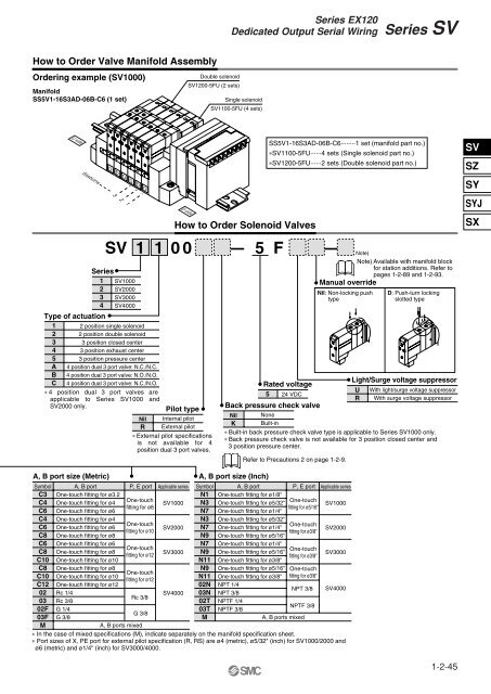
<strong>Series</strong> EX120Dedicated Output Serial Wiring<strong>Series</strong> <strong>SV</strong>How to Order Valve Manifold AssemblyOrdering example (<strong>SV</strong>1000)ManifoldSS5V1-16S3AD-06B-C6 (1 set)Double solenoid<strong>SV</strong>1200-5FU (2 sets)Single solenoid<strong>SV</strong>1100-5FU (4 sets)U sideStationsD D D D D D3 2 1<strong>SV</strong> 1 100<strong>Series</strong>1 <strong>SV</strong>10002 <strong>SV</strong>20003 <strong>SV</strong>30004 <strong>SV</strong>4000Type of actuation1 2 position single solenoid2 2 position double solenoid3 3 position closed center4 3 position exhaust center5 3 position pressure centerA 4 position dual 3 port valve: N.C./N.C.B 4 position dual 3 port valve: N.O./N.O.C 4 position dual 3 port valve: N.C./N.O.∗ 4 position dual 3 port valves areapplicable to <strong>Series</strong> <strong>SV</strong>1000 and<strong>SV</strong>2000 only.D sidePilot typeNil Internal pilotR External pilot∗ External pilot specificationsis not available for 4position dual 3 port valves.How to Order Solenoid Valves–5SS5V1-16S3AD-06B-C6········1 set (manifold part no.)∗<strong>SV</strong>1100-5FU······4 sets (Single solenoid part no.)∗<strong>SV</strong>1200-5FU······2 sets (Double solenoid part no.)FRated voltage5 24 VDCBack pressure check valve–Note) Available with manifold blockfor station additions. Refer topages 1-2-89 and 1-2-93.Manual overrideNil: Non-locking pushtypeD: Push-turn lockingslotted typeLight/Surge voltage suppressorURWith light/surge voltage suppressorWith surge voltage suppressorNil NoneK Built-in∗ Built-in back pressure check valve type is applicable to <strong>Series</strong> <strong>SV</strong>1000 only.∗ Back pressure check valve is not available for 3 position closed center and3 position pressure center.Refer to Precautions 2 on page 1-2-9.Note)<strong>SV</strong>SZSYSYJSXA, B port size (Metric)Symbol A, B portC3 One-touch fitting for ø3.2C4 One-touch fitting for ø4C6 One-touch fitting for ø6C4 One-touch fitting for ø4C6 One-touch fitting for ø6C8 One-touch fitting for ø8C6 One-touch fitting for ø6C8 One-touch fitting for ø8C10 One-touch fitting for ø10C8 One-touch fitting for ø8C10 One-touch fitting for ø10C12 One-touch fitting for ø1202 Rc 1/403 Rc 3/802F G 1/403F G 3/8P, E port Applicable seriesOne-touchfitting for ø8One-touchfitting for ø10One-touchfitting for ø12One-touchfitting for ø12Rc 3/8G 3/8<strong>SV</strong>1000<strong>SV</strong>2000<strong>SV</strong>3000<strong>SV</strong>4000A, B port size (Inch)SymbolN1N3N7N3N7N9N7N9N11N9N1102N03N02T03TMA, B portOne-touch fitting for ø1/8"One-touch fitting for ø5/32"One-touch fitting for ø1/4"One-touch fitting for ø5/32"One-touch fitting for ø1/4"One-touch fitting for ø5/16"One-touch fitting for ø1/4"One-touch fitting for ø5/16"One-touch fitting for ø3/8"One-touch fitting for ø5/16"One-touch fitting for ø3/8"NPT 1/4NPT 3/8NPTF 1/4NPTF 3/8P, E port Applicable seriesOne-touchfitting for ø5/16"One-touchfitting for ø3/8"One-touchfitting for ø3/8"One-touchfitting for ø3/8"NPT 3/8NPTF 3/8A, B ports mixed<strong>SV</strong>1000<strong>SV</strong>2000<strong>SV</strong>3000<strong>SV</strong>4000MA, B ports mixed∗ In the case of mixed specifications (M), indicate separately on the manifold specification sheet.∗ Port sizes of X, PE port for external pilot specification (R, RS) are ø4 (metric), ø5/32" (inch) for <strong>SV</strong>1000/2000 andø6 (metric) and ø1/4" (inch) for <strong>SV</strong>3000/4000.1-2-45
<strong>Series</strong> <strong>SV</strong> The serial transmission system reduces wiring work, while minimizing wiring and saving space. Maximum 16 stations (Specify a model with more than 9 stations by means of the manifold specification sheet.)Type A<strong>Series</strong> EX300Type B Mitsubishi Electric CorporationMELSECNET/MINI-S3Data Link SystemSTATION NO.U sideStationsD D D D D D3 2 1D side Stations are counted from D side as the 1st. A maximum of 16 solenoids is possible(16 stations with single solenoids).ItemSpecificationsExternal power supply 24 VDC + 10%/– 5%A, B, D, E, F1, G, J1,Current consumption 0.1 AJ2, K, R1, R2, H, U, V(Internal unit)0.3 A C, QName of terminal block, LEDNote24 V 0 V S1 S2 SG R1 R2 FGLEDTRDRUN/ERRRUNERR TRDADDRESS NO.DescriptionON during data receptionBlinks for normal data reception,ON for abnormal• Connection to T unit PLC manufacturer’s I/Ocard enables serial transmission.EX300-TMB1···· for Mitsubishi Electric CorporationEX300-TTA1···· for OMRON CorporationEX300-TFU1···· for Fuji Electric Co., Ltd.EX300-T001····· General purpose∗ Each T unit has 32 control points.• No. of output points, 16 pointsLEDPOWERRUNRDSDERRPOWERRUNSD RD ERRx 10 x 124 V 0 V SDA SDB SG RDA RDB FGDescriptionON for power supply inputON for normal data trafficwith master unitON during data receptionON during data transmissionON for data reception error,OFF when normal• MELSECNET/MINI-S3 Data Link SystemMaster unit : AJ71PT32-S3AJ71T32-S3A1SJ71PT32-S3• No. of output points, 16 points, No. of stations.occupied, 2 stationsSI manifold solenoid valveT unit OB unit SI unit SI unit Master unitRemote I/O unitRemote I/O unitCable wiringS1S2SG24 V0 VS1S2R1R2SGFG24 V0 V∗S1S2R1R2SGFG24 V0 V∗S1S2R1R2SGFG24 V0 VSDASDBRDARDBSGFG∗SDASDBRDARDBSGFGSDASDBRDARDBSGFG∗ Ground either the reception side or the transmissionside of the shielding wire shield.∗ Ground either the reception side or the transmissionside of the shielding wire shield.Type COMRON CorporationSYSBUS Wire SystemType DSHARP CorporationSatellite I/O Link SystemType EMatsushita Electric Works, Ltd.MEWNET-F SystemName of terminal block, LEDLEDRUNT/RERRRUNT/RERR14632DIP SW.24 V 0 V + - + - FGDescriptionON when transmission is normal andPLC is in operation modeBlinks when transmission is normal,ON when transmission is abnormal.LEDPOWERRUNERRR.SETHOLDPOWERRUN ERR R.SET HOLDADDRESS NO.TERM.24 V 0 V L1 L2 SG L1 L2 FG 24 V 0 V + - FG + - FGDescriptionON when power supply is ONON when power is ON andslave unit operates normallyON for abnormal slave unit switch setting,abnormal communication, master unitPLC stopped and defective slave unitON for master unit control inputLEDPOWERCOMM.ALARMPOWERCOMM. ALARMSTASTION NO.TERM.x 10 x 1 OFF ONDescriptionON when power supply is ONBlinks during datatransmission/receptionON for unit abnormality, blinks forstation no. setting errorNote• SYSBUS Wire SystemMaster unit : Type C500-RM201Type C200H-RM201• No. of output points, 16 points• Satellite I/O Link SystemJW-23LM, JW-23LMHMaster unit : ZW-31LMJW-31LM, JW-31LMH• No. of output points, 16 points• MEWNET-F SystemMaster unit : AFP3740, AFP3742AFP5740, AFP5742• No. of output points, 16 pointsMaster unit SI unit SI unita) 2-wire typeWiring does not include signal ground line (SG).ZW-31LM Master unit Slave unit 01 Slave unit 03 Slave unit 75L1L1L1L1Master unitSI unitSI unitCable wiring+–+–+–FG24 V0 VType 3 ground+–+–FG24 V0 VType 3groundL2L2SGSGSHIELDSHIELDFGTwisted pair wirewith shieldL2L2SGSGSHIELDSHIELDType 3 groundType 3 ground Type 3 ground Type 3 groundb) 3-wire typeWiring does not include signal ground line (SG).ZW-31LM Master unit Slave unit 01 Slave unit 03 Slave unit 75L1L1L1L1L2L2L2L2SGSGSGSGSHIELDSHIELDSHIELDSHIELDFGTwisted pair wirewith shieldType 3 groundType 3 ground Type 3 ground Type 3 ground+–FG+–+–FG+–FG+–FG+–FG24 V0 V24 V0 VType 3 groundType 3ground1-2-46