is after-res<strong>on</strong>ance in relati<strong>on</strong> to nature blade frequency. Thelast is c<strong>on</strong>sidered as solid body oscillati<strong>on</strong> <strong>on</strong> the hub relativeto point A (fig.2). It allows not <strong>on</strong>ly to remove a variablehydrodynamic load with torque but also makes it possible toexclude transverse forces arising in case <str<strong>on</strong>g>of</str<strong>on</strong>g> the PSBC operati<strong>on</strong>in oblique flow and, as a result, to decrease the hydrodynamictorque necessary to rotate the steering thruster beingused as a steering device during the ship’s moti<strong>on</strong>.The mechanism <str<strong>on</strong>g>of</str<strong>on</strong>g> transverse force arising <strong>on</strong> a traditi<strong>on</strong>alscrew propellers operating in oblique flow is well known.The transverse force arises due to tangential force providingthe torque relative <str<strong>on</strong>g>of</str<strong>on</strong>g> propeller axis. It is less when the bladeis moving with oblique flow then quantity <str<strong>on</strong>g>of</str<strong>on</strong>g> the same forcearising <strong>on</strong> the blade and moving opposite oblique flow. As aresult the summarized force named as transverse force doesnot turn into zero. Similar picture is being watched at themovable blades. However in this case due to oscillating atthe after res<strong>on</strong>ance mode an additi<strong>on</strong>al inertia force causedby mass <str<strong>on</strong>g>of</str<strong>on</strong>g> blade and additi<strong>on</strong>al water mass is observed. Thedirecti<strong>on</strong> <str<strong>on</strong>g>of</str<strong>on</strong>g> this force is opposite to variable hydrodynamicforce that is why the last may be compensated c<strong>on</strong>siderablyby the menti<strong>on</strong>ed before. As a result, the transverse forcemay not be present <strong>on</strong> the blade <str<strong>on</strong>g>of</str<strong>on</strong>g> PBSC, which in turn maycompletely exclude the c<strong>on</strong>tributi<strong>on</strong> <str<strong>on</strong>g>of</str<strong>on</strong>g> transverse force intothe hydrodynamic torque arising <strong>on</strong> the steering thruster.3. MODEL EXPERIMENT, DESIGN O SHITED BLADEAND EVALUATION O EICIENCYThe results <str<strong>on</strong>g>of</str<strong>on</strong>g> modal comparative tests in cavitati<strong>on</strong> tunnel<str<strong>on</strong>g>of</str<strong>on</strong>g> the Krylov Institute illustrate the general picture <str<strong>on</strong>g>of</str<strong>on</strong>g>hydrodynamics characteristics, see fig. 3, 4.Êå, 10*KQ0,60,50,40,30,20,100 0,2 0,4 0,6 0,8 1 1,2Jig. 3. Hydrodynamics characteristics, PP, (n) andPSBC (p)0 , 1 10 , 0 9Kq0 , 10 , 0 80 , 0 70 , 0 60 0 , 2 0 , 4 0 , 6 0 , 8 1 1 , 2Jig. 4. Changing <str<strong>on</strong>g>of</str<strong>on</strong>g> coefficient <str<strong>on</strong>g>of</str<strong>on</strong>g> transverse force,PP(n), PSBC(p)The hydrodynamic curves <str<strong>on</strong>g>of</str<strong>on</strong>g> PBSC look more flatten thenthose <str<strong>on</strong>g>of</str<strong>on</strong>g> the fixed blade propeller (PP), fig. 3. Geometry <str<strong>on</strong>g>of</str<strong>on</strong>g>blades <str<strong>on</strong>g>of</str<strong>on</strong>g> the propellers being compared is similar. The testedPSBC was designed for flow without oblique flow that iswhy the full compensati<strong>on</strong> <str<strong>on</strong>g>of</str<strong>on</strong>g> transverse force arising in obliqueflow by inertia load are not realized, fig. 4. At the sametime the results show that coefficient <str<strong>on</strong>g>of</str<strong>on</strong>g> transverse force relatedto “free” blades in wide range <str<strong>on</strong>g>of</str<strong>on</strong>g> mode operati<strong>on</strong> (inthe range <str<strong>on</strong>g>of</str<strong>on</strong>g> advance ratio J= 0.2÷0.85) is less then the samecoefficient related to PP.Let us find the c<strong>on</strong>diti<strong>on</strong> that will be met by the geometry<str<strong>on</strong>g>of</str<strong>on</strong>g> shifted blade and provided the complete compensati<strong>on</strong><str<strong>on</strong>g>of</str<strong>on</strong>g> transverse force by inertial load. The forces being the result<str<strong>on</strong>g>of</str<strong>on</strong>g> liquid effecting <strong>on</strong> the blade may be defined accordingto hydrodynamics characteristics obtained in forward flowdepending <strong>on</strong> the instant advance ratio according to formulaJ0sinδJ = J0cosδ/(1 − C sin β ) (1)π 0.67where J 0– design value <str<strong>on</strong>g>of</str<strong>on</strong>g> advanced ratio; δ – angle <str<strong>on</strong>g>of</str<strong>on</strong>g> obliqueflow; C – experimental coefficient, defined in depending<strong>on</strong> the propeller load and oblique flow and taking intoaccount the effect <str<strong>on</strong>g>of</str<strong>on</strong>g> n<strong>on</strong>-stati<strong>on</strong>ary; β = ωt – angle <str<strong>on</strong>g>of</str<strong>on</strong>g> rotati<strong>on</strong><str<strong>on</strong>g>of</str<strong>on</strong>g> blade, (ω = 2πn, t – time, n – frequency <str<strong>on</strong>g>of</str<strong>on</strong>g> rotati<strong>on</strong>propeller).Knowing the minimum and maximum values <str<strong>on</strong>g>of</str<strong>on</strong>g> instantadvance ratio from the formula (1) it is easy to define thetransverse force arising in oblique flow <strong>on</strong> PP. It will beequal to:Z QKmax− Q ∆minQZ = = k = kρ2 4, (2)n D r 0.670where ∆K Q– range <str<strong>on</strong>g>of</str<strong>on</strong>g> oscillati<strong>on</strong> <str<strong>on</strong>g>of</str<strong>on</strong>g> hydrodynamic momentcoefficient; Q max, Q min– minimum and maximum <str<strong>on</strong>g>of</str<strong>on</strong>g> valueshydrodynamic moment coefficients; r 0= 0.67D/2 (D – propellerdiameter); k – coefficient which takes into account thedeflecti<strong>on</strong> <str<strong>on</strong>g>of</str<strong>on</strong>g> transverse force from its maximum value whichis acting <strong>on</strong> it during <strong>on</strong>e turn <str<strong>on</strong>g>of</str<strong>on</strong>g> the propeller.In case <str<strong>on</strong>g>of</str<strong>on</strong>g> sinusoidal changing <str<strong>on</strong>g>of</str<strong>on</strong>g> the force menti<strong>on</strong>ed(which is close to oblique flow) coefficient k = 0.64. Thus itmay be c<strong>on</strong>cluded thatZ ≈ ∆K Q(3)In case <str<strong>on</strong>g>of</str<strong>on</strong>g> shifted blades in propeller disk the inertiamoment is acting in the opposite directi<strong>on</strong> relative to thehydrodynamic moment. The quantity <str<strong>on</strong>g>of</str<strong>on</strong>g> the last relative tothe axis <str<strong>on</strong>g>of</str<strong>on</strong>g> rotati<strong>on</strong> <strong>on</strong> the hub is defined by the formula''2QI= JAψ= −JAAωsin β , (4)where A – amplitude <str<strong>on</strong>g>of</str<strong>on</strong>g> angle blade shifting; J A– inertiamoment <str<strong>on</strong>g>of</str<strong>on</strong>g> blade together with additi<strong>on</strong>al moments relativeto axis <str<strong>on</strong>g>of</str<strong>on</strong>g> its rotati<strong>on</strong> <strong>on</strong> the hub.Then, transverse force c<strong>on</strong>nected with blade mass and additi<strong>on</strong>almass relative to axis <strong>on</strong> the hub and directed againstto transverse hydrodynamics force is defined with the formulaQIm − Q 2JAω2ax Im in AZI= =, (5)rIrIwhere r I– inertia reduce <str<strong>on</strong>g>of</str<strong>on</strong>g> blade together with additi<strong>on</strong>almoment <str<strong>on</strong>g>of</str<strong>on</strong>g> inertia relative to the axis <str<strong>on</strong>g>of</str<strong>on</strong>g> rotati<strong>on</strong> <strong>on</strong> the hub.In case <str<strong>on</strong>g>of</str<strong>on</strong>g> shifting blades in propeller disk the coefficient<str<strong>on</strong>g>of</str<strong>on</strong>g> transverse force may be defined as222JAAωπ ρbZΣ = Z − ZI= ∆KQ− = ∆KQ− JAA2 4, (6)rIρnD 2 ρwhere ρ and ρ b– water density and density <str<strong>on</strong>g>of</str<strong>on</strong>g> blade materialc<strong>on</strong>sequently.Let us suggest that geometry <str<strong>on</strong>g>of</str<strong>on</strong>g> PSBC is designed insuch a way that compensati<strong>on</strong> <str<strong>on</strong>g>of</str<strong>on</strong>g> transverse force is full. Suchevaluati<strong>on</strong> t in decreasing hydrodynamics moment which isneeded to steering thruster with PSBC when it is used as90 Ìîðñêîé âåñòíèê ¹ 3(15), 2005
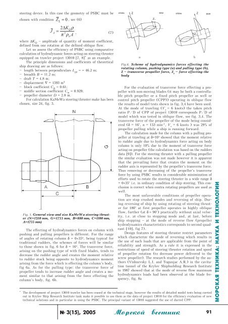
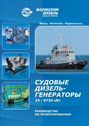
steering device. In this case the geometry <str<strong>on</strong>g>of</str<strong>on</strong>g> PSBC must bechosen with c<strong>on</strong>diti<strong>on</strong> Z 0 , see (6)JAΣ=2∆KQρ2π ρ A= , (7)where ∆K Q– amplitude <str<strong>on</strong>g>of</str<strong>on</strong>g> quantity <str<strong>on</strong>g>of</str<strong>on</strong>g> moment coefficient,defined from <strong>on</strong>e rotati<strong>on</strong> at the defined oblique flow.Let us assess the efficiency <str<strong>on</strong>g>of</str<strong>on</strong>g> PSBC using comparativecalculati<strong>on</strong> <str<strong>on</strong>g>of</str<strong>on</strong>g> hydrodynamic forces acting <strong>on</strong> steering thrusterequipped <strong>on</strong> trawler project 13010 [7, 8] * as an example.The principle dimensi<strong>on</strong>s and coefficients <str<strong>on</strong>g>of</str<strong>on</strong>g> theoreticalship drawing are as follows:–length between perpendiculars L pp= = 46.2 m;–breadth B = 11.2 m;–draft Ò = 4.8 m;–displacement ∇ = 1593 m 3–block coefficient Ñ Â= 0.61;–middle secti<strong>on</strong> coefficient Ñ ò= 0.929;–propeller diameter D = 2.8 m.or calculati<strong>on</strong> KaMeWa steering thruster make has beenchosen, size 24, fig. 5.ig. 5. General view and size KaMeWa steering thruster(N=1310 mm, G=1755 mm, B=880 mm, C=1100 mm,A=1755 mm)The effecting <str<strong>on</strong>g>of</str<strong>on</strong>g> hydrodynamics forces <strong>on</strong> column withpushing and pulling propellers is different. or the range<str<strong>on</strong>g>of</str<strong>on</strong>g> angles <str<strong>on</strong>g>of</str<strong>on</strong>g> rotating column δ = 0÷35 î , being typical fortraditi<strong>on</strong>al rudders, the schemes <str<strong>on</strong>g>of</str<strong>on</strong>g> forces will be similarto those shown in fig. 6 for δ = 16 î . The transverse force,arising <strong>on</strong> the pushing type <str<strong>on</strong>g>of</str<strong>on</strong>g> with fixed blades, tends todecrease the rudder angle and creates the moment relativeto rudder stock being opposite to hydrodynamics momentarising from the force which is effecting the column’s body,fig 6a. As for the pulling type: the transverse force <str<strong>on</strong>g>of</str<strong>on</strong>g>propeller tends to increase rudder angle and creates a momentsimilar to that arising from the force effecting thecolumn’s body, fig. 6b.bor the evaluati<strong>on</strong> <str<strong>on</strong>g>of</str<strong>on</strong>g> transverse force effecting a propellerwith n<strong>on</strong>-moving blades (it may be both a c<strong>on</strong>trollablepitch propeller or a fixed pitch propeller as well orc<strong>on</strong>trol pitch propeller (CPP)) operating in oblique flowthe results <str<strong>on</strong>g>of</str<strong>on</strong>g> model tests shown in fig. 3,4 have been used.At the mode <str<strong>on</strong>g>of</str<strong>on</strong>g> trawling (V s= 6 knots) the taken pitchratio P/D <str<strong>on</strong>g>of</str<strong>on</strong>g> CPP <str<strong>on</strong>g>of</str<strong>on</strong>g> project 13010 corresp<strong>on</strong>ds P/D <str<strong>on</strong>g>of</str<strong>on</strong>g>model which was tested in oblique flow, see fig. 3,4. Thetransverse force <str<strong>on</strong>g>of</str<strong>on</strong>g> the propeller <str<strong>on</strong>g>of</str<strong>on</strong>g> the mode being c<strong>on</strong>sidered(δ = 16°, n = 153 min -1 , V s= 6 knots ) was 29% <str<strong>on</strong>g>of</str<strong>on</strong>g>propeller pulling while a ship is running forward.The calculati<strong>on</strong> made for the column with a pulling propellerat trawling at δ=16 î showed that the moment relativeto rudder angle due to hydrodynamics force acting <strong>on</strong> bodycolumn is <strong>on</strong>ly 10% due to the moment <str<strong>on</strong>g>of</str<strong>on</strong>g> transverse forceacting <strong>on</strong> propeller (the calculati<strong>on</strong> was based <strong>on</strong> the ruddersdata [9]). or the steering thruster with a pulling propellerthe similar evaluati<strong>on</strong> was not made however it is apparentthat the prevailing force that creates the moment <strong>on</strong> therudder axis is represented by the propeller’s transverse force.Thus removing or decreasing <str<strong>on</strong>g>of</str<strong>on</strong>g> the propeller’s transverseforce by using PSBC results in c<strong>on</strong>siderable minimizati<strong>on</strong> <str<strong>on</strong>g>of</str<strong>on</strong>g>efforts used to rotate the steering thruster in a wide range δ= 0÷35° i.e. in ordinary c<strong>on</strong>diti<strong>on</strong> <str<strong>on</strong>g>of</str<strong>on</strong>g> ship steering. This c<strong>on</strong>clusi<strong>on</strong>is correct when c<strong>on</strong>tra rotating propellers are used aswell.The most unfavorable c<strong>on</strong>diti<strong>on</strong>s <str<strong>on</strong>g>of</str<strong>on</strong>g> propeller operati<strong>on</strong>are stop crushed modes and reversing <str<strong>on</strong>g>of</str<strong>on</strong>g> ship. Duringreversing <str<strong>on</strong>g>of</str<strong>on</strong>g> ship by using rotating <str<strong>on</strong>g>of</str<strong>on</strong>g> steering thrusterfor 180° at first propeller operates in highly obliqueflow, further (at δ ≈ 90°) practically without axial velocity,i.e. at close to stopping mode and, at last, beforeship stopping – at the mode <str<strong>on</strong>g>of</str<strong>on</strong>g> reverse flow (propellerhydrodynamics characteristics corresp<strong>on</strong>ds to sec<strong>on</strong>d quadrant[10], fig 7).Design features <str<strong>on</strong>g>of</str<strong>on</strong>g> steering thruster restrict parameterswhich characterize the mode <str<strong>on</strong>g>of</str<strong>on</strong>g> reversing which results inthe use <str<strong>on</strong>g>of</str<strong>on</strong>g> such loads that are applicable from the point <str<strong>on</strong>g>of</str<strong>on</strong>g>reliability and strength. As a rule it is expressed in therestricti<strong>on</strong>s <str<strong>on</strong>g>of</str<strong>on</strong>g> speed <str<strong>on</strong>g>of</str<strong>on</strong>g> steering thruster rotati<strong>on</strong> and speed<str<strong>on</strong>g>of</str<strong>on</strong>g> propeller rotati<strong>on</strong> (to decrease power delivered to thescrew propeller). The research studies performed by the authors(Vishnevsky L.I. and Togunjac A.R.) in the cavitati<strong>on</strong>tunnel <str<strong>on</strong>g>of</str<strong>on</strong>g> the Krylov Shipbuilding Research Institutein 1987 showed that at the mode <str<strong>on</strong>g>of</str<strong>on</strong>g> reverse flow maximumhydrodynamics loads had been observed at the blade frequency,fig. 8a* The development <str<strong>on</strong>g>of</str<strong>on</strong>g> project 13010 trawler has been ceased at the technical stage, however the results <str<strong>on</strong>g>of</str<strong>on</strong>g> detailed model tests being carriedout in Krylov Ship Research Institute tank make it possible to use them as the data <str<strong>on</strong>g>of</str<strong>on</strong>g> project 13010 for the efficiency evaluati<strong>on</strong> <str<strong>on</strong>g>of</str<strong>on</strong>g> newtechnical soluti<strong>on</strong>s and in particular in using the PSBC. The principal variant <str<strong>on</strong>g>of</str<strong>on</strong>g> 13010 suggested the use <str<strong>on</strong>g>of</str<strong>on</strong>g> ducted CPP.àig.6. Scheme <str<strong>on</strong>g>of</str<strong>on</strong>g> hydrodynamics forces effecting therotating column, pushing type (a) and pulling type (b),Z – transverse propeller force, Z p– force effecting thebodybìîðñêàÿ òåõíèêà: íàóêà è òåõíîëîãèè¹ 3(15), 2005 Ìîðñêîé âåñòíèê91