
Create successful ePaper yourself
Turn your PDF publications into a flip-book with our unique Google optimized e-Paper software.
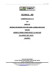
TENDER NO. 1/ FK/ 2010Addition & alteration workAtFluorspar project , Kadipani ,Tal: KawantDist: Vadodara<strong>TECHNICAL</strong> <strong>BID</strong><strong>PART</strong>- I IGUJARAT MINERAL DEVELOPMENT CORPORATION LIMITED(A Govt. of Gujarat Enterprise)Khanij Bhavan, Near University Ground, 132 feet Ring Road,Vastrapur, Ahmedabad-380 052Phone : (079) 27913200, 27913501 Fax No : (079) 27911454Website www.gmdcltd.comPage 1 of 157
CHAPTER- VI DETAIL CONDITIONS OF CONTRACTSr. No Particulars01 Definitions02 Contract Documents03 Type of Contract04 Schedule of Quantities05 Drawings06 Contract Sum07 Contract Bills08 Scope & Intent09 Engineers Instructions10 Facilities & Co-operation11 Setting Out12 Site13 Samples & Shop Drawings14 Progress Chart15 Access for Engineer to the Works16 Engineer’s status & decisions17 Performance Bond18 Clerk of Works19 Contractors field Organisation & Equipment20 Taxes21 Statutory obligations, notices, fees & charges22 Royalties & patent Rights23 Licenses & Permits for materials under Govt.control24 Water & Electric Power for construction25 Assignments or sub-letting26 Sub – Contractor27 Prime Cost28 Artists & tradesman29 Separate Contractors30 Variations, Provisional & Prime Cost Sums31 Certificates & payments32 Claim for Extra33 Deduction for uncorrected work34 Fluctuations35 Unfixed goods & materials36 Materials & Workmanship37 Defects38 Possession, Completion & Postponement39 Virtual Completion40 ExtensionPage 2 of 157
Sr. NoParticulars41 Damages for non-completion42 Virtual Completion & Defects Liability Period43 Loss & expense caused by disturbance ofregular progress of the works44 Payments withheld45 Indemnity for Injury to persons & property46 Insurance against injury to Persons & Property47 Insurance of the Works against fire etc.48 Determination by <strong>GMDC</strong>DI/249 Determination by the Contractor50 Co-ordination of Work51 Labour52 Protection of trees and shrubs53 Guarantee54 Antiquities55 Excepted matters56 Arbitration57 Protection and Cleaning58 Tolerance59 Bribery60 Declaration against Waiver61 Indemnity of <strong>GMDC</strong>’s Agents and Engineerand Engineer’s Agents62 Members of <strong>GMDC</strong>’s Staff, etc. Not liable63 Return of Surplus Materials64 Concurrent Delays65 Rate of Progress66 Advance payment67 Day workExamination of work before Covering upWorks or Execution to be Deferred TemporarilyFire PrecautionsSECTION - D: GENERAL CONDITIONS OF CONTRACTPage 3 of 157
1. Definitions1.(1) The Contract Document consists of the Agreement, the General Conditions of theContract, Special conditions of the contract, Specifications and Bills of Quantities includingall modifications thereof incorporated in the document before the execution and theContract Drawings prepared by the Architect and the Consultant from time to time. Theseform the contract.1. (2) Owner/Client/Employer: Gujarat Mineral DevelopmentCorporation limited. AhmedabadContractor:Successful TendererArchitectEngineer:The Clerk of Work: Same as EngineerEngineer In-charge: Engineer of ________ of <strong>GMDC</strong>Site In-charge:Contractor’s Senior EngineerAre those mentioned as such in the Agreement and shall include their legalrepresentatives, assigns or successors.1.(1) "The Site" shall mean the site of the Contract work including any building anderections thereon and any other land allotted by the Employer (Gujarat MineralDevelopment Corporation Limited., Ahmedabad) hereafter referred to as <strong>GMDC</strong>) forContractor's use.1.(2) The term "Sub-Contractor", as employed herein, includes those having a directcontract with the Contractor and it includes one who furnishes material worked to a specialdesign according to the plans or specifications of this work but does not include one whomerely furnishes material not so worked. Any one doing work on a piece rate basis shall bedeemed a Sub-Contractor.1.(3) Written notice shall be deemed to have been duly served if delivered in person to theindividual or to a member of the firm or to an office of the corporation for whom it isintended, or if delivered at or sent by registered mail to the last business address known tohim who gives the notice.1. (4) The term "Work", of the Contractor or Sub-Contractor includes labour or material orboth.1. (5) All time limits stated in the Contract Document are the essence of the contract.1. (6) The law of the place of work shall govern the construction under this contract.1.(7) The date of virtual completion of a project or specified area of a project is the datewhen construction is sufficiently completed, in accordance with the Contract Documents asmodified by any change or variation orders agreed to by the parties, so that <strong>GMDC</strong> canoccupy the project for the use it was intended.2. Contract Document2. The following documents shall constitute the Contract Document:Conditions of TenderingForm of TenderArticles of AgreementGeneral and Special Conditions of ContractSpecificationsScope of WorkBills of QuantitiesTender DrawingsDay work ScheduleSchedule of basic PricePage 4 of 157
The Contract Document is complementary. What is called for in any one shall be as bindingas if called for by all.The Contract Document shall remain in the custody of <strong>GMDC</strong> so as to be available at allreasonable times for the inspection of the Contractor. Immediately after the execution of theContract one copy of the Contract Document shall without charge be supplied by <strong>GMDC</strong> tothe ContractorAfter the award of the Contract the Contractor shall without charge be supplied with all suchfurther drawings and details as may be prepared by the Engineer and the Architect, fromtime to time as the work proceeds as are reasonably necessary either to explain or amplifythe Contract Drawings or to enable the Contractor to carry out and complete the work inaccordance with these Conditions.The Contractor shall keep one copy of the Specifications, Descriptive schedule or other likedocument referred to in this clause and one copy of the Contract Drawings and such otherdrawings and details supplied to him from time to time and referred to in this clause andwritten instructions referred to in clause and sub-clause 9, 16(1), 16(2) and 30 upon the siteso as to be available to the Engineer or the Architect or <strong>GMDC</strong> at reasonable times.None of the document herein before mentioned shall be used by the Contractor for anypurpose other than this Contract.Upon final payment under clause 31(6) of these Conditions, the Contractor shall forthwithreturn to the Engineer and the Architect all Drawings, Details, Specifications, DescriptiveSchedule and other Document of like nature which bears his name or that of the Engineerand/or the Architect.3. Type of ContractThe Contract shall be fixed item-rate contract. The Contractor shall be paid for the actualquantity of work done, as per drawing and measured at site, at the rates quoted by him inthe Contract Bills.Contractor’s rates shall remain unchanged although the actual quantities may be differentfrom those shown in the Bill of quantities. The quoted item rates shall be inclusive of all theliabilities / responsibilities relating to contract labour laws / Insurance / Provident Funds andany statutory liability etc. and no variation in prices will be effected for that purpose. Any risein the quoted item rates due to escalation in cost of materials, labour, increase in anyexisting taxes or imposition of any new taxes etc shall have to be borne by the Contractorand the rates shall not be subject to any change whatsoever.The basis of price is FIRM and free from any kind of escalation including statutory leviesthroughout the validity of the agreed rates. No escalation towards any variation in cost oflabour, plant & machinery, currency fluctuations, Petroleum products, Electricity will beconsidered during the validity of contract. The prices are inclusive supply of all material Theprices are inclusive of all applicable taxes, duties, levies, transportation, insurance andworkman’s compensation. The prices are inclusive of work contract tax if applicable.The unit rates will be valid for a period of as defined in the LOI/PO/Work order from the dateof work order.No extra claim/compensation will be entertained for idle time.Page 5 of 157
The rates agreed in schedule of rates shall cover for all charges and expenses. Quantitiesmentioned in the Bill of quantities are indicative ones, which have been estimated based onassumed details. The Contractor must verify & workout the actual requirements based onthe construction drawings which shall be issued to contractor before ordering of materialsand / or starting the job and the Owner / Consultant shall not be responsible for delay incompletion and any extra cost to the Contractor due to shortfall or excess purchases doneby the Contractor.4. Schedule of Quantities - Procurement of materials based on drawings and(not Bill of Materials)5. DrawingsThe schedule of Quantities given in the Contract Bill are provisional and are meant toindicate the intent of the work and to provide a uniform basis for tendering. <strong>GMDC</strong> reservesthe right to increase or decrease any of the quantities to any extent or to totally omit anyitem of work and the Contractor shall not claim any extras or damages on these grounds.Any error in description or in quantity or omission of items from the Contract Bill shall notvitiate this Contract but shall be treated as a variation.5.(1) Tender DrawingTender drawings describe the general nature of works. However, there may be substantialvariation in these and detailed execution drawings issued to the Contractor from time totime. Such variations will not vitiate the Contract.5.(2) Further Drawings and InstructionsThe Engineer, the Architect and <strong>GMDC</strong> shall have full power and authority to supply to theContractor from time to time, during the progress of the works, such further drawings andinstructions as shall be necessary for the purpose of the proper and adequate executionand maintenance of the Works. The Contractor shall carry out and be bound by the same.5.(3) Disruption of ProgressThe Contractor shall give written notice to <strong>GMDC</strong> or the Engineer or the Architect wheneverplanning or progress of the Works is likely to be delayed or disrupted unless any otherdrawing or order, including a direction, instruction or approval, is issued by the Engineer orthe Architect or <strong>GMDC</strong> within a reasonable time. The notice shall include details of thedrawings or order required and of why and by when it is requiredand of any delay or disruption likely to be suffered if it is late.5.(4) Contract Drawings.5.(4) A In general the Drawings shall indicate dimensions, position and type ofconstruction; the Specifications shall indicate the qualities and the methods; and the Bill ofQuantities shall indicate the quantum and the rate for each item of work. Any work indicatedon the Drawings and not mentioned in the specifications or vice versa shall be deemed asthough fully set forth in both. Work not specifically detailed, called for, marked or specifiedshall be the same as similar parts that are detailed, marked or specified.5.(4) B The Contractor's work shall not deviate from the Drawings and thePage 6 of 157
Specifications. The Engineer or <strong>GMDC</strong>'s interpretation of these documents shall be finaland without appeal.5.(4) C Errors or inconsistencies discovered in the Drawings and Specifications shall bepromptly brought to the attention of the Architect and/or the Engineer for interpretation orcorrection. Local conditions which may affect the work shall likewise be brought to theArchitect and/or Engineer's attention. If at any time, it is discovered that work is being donewhich is not in accordance with the Contract Drawings and Specifications, the Contractorshall correct the work immediately. Corrections of defective work shall not be a basis forany claim for extension of time and or money. The Contractor shall not carry on workexcept with the knowledge of the Clerk-of- works.5.(4) D Figured dimensions on the Scale Drawings and large size details shall govern. Largesize details shall take precedence over small scale drawings. Any work done beforereceipt of such details, if not in accordance with the same, shall be removed and replacedor adjusted by the Contractor, as directed without expense to <strong>GMDC</strong>. The generalconditions apply with equal force to all the work including authorized extraworks.5.(4) E All Drawings, Bills of Quantities and Specifications and copies thereof furnished bythe Engineer are his property. They shall not be used on any other work and shall bereturned to the Engineer at his request on completion or termination of the Contract.5.(4) F Reinforcing steel bar bending schedules shall if requested by the Engineer beFurnished to the Engineer at least fifteen days prior to the fabrication of the reinforcement.6. Contract Sum6. The Contract Sum shall not be adjusted or altered in any way whatsoever otherwisethan in accordance with the express provisions of these conditions, and subject to clause5(4) B of these Conditions. Any error whether of Arithmetic or not in the computation of theContract Sum shall be deemed to have been accepted by the parties hereto.7. Contract Bills7.(1) The quality and quantity of the work included in the Contract Sum shall be deemedtobe that which is set out in the Contract Bills. Nothing contained in the Contract Bill shalloverride, modify or affect in any way whatsoever the application or interpretation of thatwhich is contained in these conditions.7.(2) Any error in description or in quantity or omission of items from the Contract Billsshall not vitiate this Contract but shall be corrected and deemed to be a variation requiredby the Engineer.8. Scope and Intent8.(1) Scope : The general character and the scope of the work is illustrated and definedby the Specifications and the Bills of Quantities herewith attached and by the Drawings. Ifthe Contractor shall find any discrepancy in or divergence between the Contract Drawingand/or the Contract Bills he shall immediately give to the Engineer a written notice specifyingthe discrepancy or divergence and the Engineer shall issue instruction in regard thereto.8.(2) Extents : The Contractor shall carry out and complete the work in every respect inaccordance with this Contract and with the direction of and to the reasonable satisfaction ofPage 7 of 157
the Engineer. The Engineer may in his absolute discretion and from time to time issuefurther Drawings, details and/or written instructions, written directions and writtenexplanations all of which are collectively referred to as Engineer's instructions.8.(3) Intent : The intention of the Document is to include all labour and materials, taxesand Government duties, equipment and transportation necessary for the proper executionof the work.9. Engineers Instructions9.(1) The Contractor shall forthwith comply with and duly execute any works comprised insuch instructions issued to him by Engineer in regard to any matter in respect of which theEngineer is expressly empowered by these Conditions to issue instructions provided alwaysthat verbal instructions, directions and explanations given to the Contractor or his workrepresentative by the Engineer shall, if involving a variation, be confirmed in writing. If withinseven days after receipt of a written notice from the Engineer, requiring compliance with aninstruction the Contractor does not comply herewith, then <strong>GMDC</strong> may employ and payother persons to execute any work whatsoever which may be necessary to give effect tosuch instructions and all cost incurred with such employment shall be recoverable from theContractor by <strong>GMDC</strong> as debt or may be deducted by him from any monies due or tobecome due to the Contractor under this Contract.9.(2) Upon receipt of what propose to be an instruction issued to him by the Engineer, theContractor may request the Engineer to specify in writing the provision of these conditionswhich empowers the issue of the said instruction. The Engineer shall forthwith comply withany such request, and if the Contractor shall thereafter comply with the said instruction, thenthe issue of the instruction shall be deemed for all purposes of this Contract to have beenempowered by the provision of these Conditions specified by the Engineer in answer to theContractor's request.9.(3) All instructions issued by the Engineer shall be in writing. Any instruction issuedorally shall be of immediate effect, but shall be confirmed in writing by the Contractor to theEngineer within seven days, and if not dissented from in writing by the Engineer to theContractor within seven days from receipt of the Contractor's confirmation, shall take effectas from the expiration of the latter said seven days. Provided always :9.(3)A. That if the Engineer within seven days of giving such an oral instruction shall himselfconfirm the same in writing, then the Contractor shall not be obliged to confirm asaforesaid, and the said instruction shall take effect as from the date of the Engineer'sconfirmation and9.(3)B. That if neither the Contractor nor the Engineer shall confirm such an oral instructionin the manner and at the time aforesaid but the Contractor shall nevertheless comply withthe same, then the Engineer may confirm the same in writing at any time prior to the issueof the Final Certificate, and the said instruction shall thereupon be deemed to have takeneffect on the date on which it was issued.10. Facilities and Co-operation10. In the case of works indicated on the Drawings but not included in the Contract theContractor shall provide necessary facilities and co-operation for any Sub- contractor orsupplier who may be approved by <strong>GMDC</strong>. The Contractor shall do all cutting, filling orpatching of his work that may be required to make its several parts come togetherproperly and fit it to receive or be received by work of other Contractors shown upon orreasonably implied by the Drawings and Specifications for the completed structure, and heshall make good after them as the Engineer may direct. Any cost caused by the defectiveor ill-timed work shall be borne by the party responsible therefore.Page 8 of 157
The Contractor shall not endanger any work by cutting, excavating or otherwise altering thework and shall not cut or alter the work of any other Contractor save with the consent of theEngineer.11. Setting out12. Site11. The Engineer shall determine any lines levels which may be required for theexecution of the work and shall furnish to the Contractor by way of accurately dimensioneddrawings such information as shall enable the Contractor to set out the Work at groundlevel. The Contractor shall set out and level the work and shall be responsible for theaccuracy of the same. He shall provide all the instruments and attendance required by theEngineer for checking the work. He shall entirely at his own cost amend to the satisfactionof the Engineer any error found at any stage which may arise through inaccurate setting.12.( 1) Visit : Before tendering, the Contractor shall have visited and examined the siteand satisfied himself as to the nature of the existing roads or other means ofcommunication and the character of the soil and of the excavations, the correct dimensionsof the work and the facilities for obtaining any special articles called for in the ContractDocument andshall have obtained generally his own information on all matters affectingthe continuation and progress of the works.No extra charge made in consequence of any misunderstanding or incorrect information onany of these points, or on the grounds of insufficient description, will be allowed. Should theContractor after visiting the site, find any discrepancies, omissions, ambiguities or conflictsin or among the Contract Document, or to be in doubt as to their meaning, he shall bringthe questions to the Engineer's attention, not later than seven days before the last date forsubmission of the tender.12. (2) Possession : The Contractor shall be allowed admittance to the site on the 'Date ofCommencement' stated in the Appendix and he shall thereupon and forthwith begin thework and shall regularly proceed with and complete the same on or before the 'Date ofCompletion' stated in the Appendix subject nevertheless to the provision for extension oftime hereafter contained.12.(3) Treasures : Any Treasures, Coins or objects of Antiquity, which may be found at siteshall be the property of <strong>GMDC</strong> and handed over to <strong>GMDC</strong>.12.(4) Use of Site In particular the following provisions shall be deemed to apply to thepossession and use of the Site.12.(4)A The lands and other places outside the Site which are the property of or under thecontrol of <strong>GMDC</strong> shall be used strictly in accordance with the instructions of the Engineer orClerk of Works.12.(4)B The Contractor shall at any time move any vehicle, machine, vessel or any otherobstruction within his control that may be required by the Clerk of Works to be moved suchthings or such obstructions promptly on instructions being given and at his own cost unlessthe Clerk of Works decides otherwise.12.(4)C The Contractor shall maintain access for the inspection, operation and maintenanceof any of the plant or the Works belonging to <strong>GMDC</strong> which lie within the Site or elsewhere.Page 9 of 157
12.(4)D The Contractor shall not use any portion of the Site for any purpose not connectedwith the Works unless prior written permission of the Clerk of Works shall have beenobtained.13. Samples and Shop Drawings13.(1) After the award of the Contract, the Contractor shall furnish for the approval of theEngineer, with such promptness as to cause no delay in his work or in that of any otherSub-Contractor, samples and shop drawings required by the Engineer. Samples shall bedelivered as directed by the Engineer. The shop / fabrication drawings shall be prepared bythe contractor at his own cost and got approved by the Engineer.13.(2) A schedule giving dates for the submission of samples shall be included in theschedule described under clause 14. Unless specifically authorized all samples must besubmitted for approval within thirty days of signing the Contract and not less than sixty daysbefore the date of the particular work involved is scheduled to begin.13.(3) The Engineer shall check and approve such samples, with reasonable promptnessonly for conformity with the design concept of the project and for compliance with theinformation in the Contract Documents. The Work shall be in accordance with the approvedsamples.13.(4) All samples for testing of sand, aggregate, cement, reinforcing bars, concrete blocks,timber and other materials used in construction of the buildings and services shall besupplied by the Contractor at his own cost, if the material/product is to be supplied by him. If<strong>GMDC</strong> has supplied the material/product, the cost of samples shall be borne by him.13.(5) The Contractor shall submit to the Engineer samples of materials/products forapproval sufficiently in advance of incorporating the same in the Works.13.(6) The Contractor shall inform <strong>GMDC</strong>, requirement of all materials to be supplied by<strong>GMDC</strong> one month in advance before actual use of the materials for the works and shallcooperate with <strong>GMDC</strong> for procurement of the said materials.13.(7) The Contractor shall prepare test specimens for different types of plaster, paintingetc. at his own cost for approval by the Engineer.13.(8) The Contractor shall prepare bar-bending schedules for reinforcement at his owncost on the basis of construction drawings issued to him by the Engineer.14. Progress Chart14.(1) The Contractor shall prepare progress charts and submit the same for approval ofthe Engineer and for his record within twenty-one days of the Award of the Contract. Thecharts shall indicate the expected date of commencement and completion of each of theitems of the work and shall be in a form approved by the Engineer. The chart shall alsoindicate the scheduling of samples, Shop Drawings and approvals.The Contractor shall, whenever required by the Engineer, also provide in writing for hisinformation a general description of the arrangements and method which the Contractorproposes to adopt for execution of the Works.14.(2) If at any time it should appear to the Engineer that the actual progress of the Worksdoes not conform to the program to which consent has been given under sub- clause 14.1,the Contractor shall produce within a week's time at the request of the Engineer, a revisedprogram showing the modifications to such program necessary to ensure completion of theWork within the Time for Completion.Page 10 of 157
14.(3) The Contractor shall, if required any time by the Engineer, deliver to the Engineer areturn in detail, in such form and at such interval as the Engineer may prescribe showingthe status of work by the Contractor at site.14.(4) Records :The Contractor shall, at his own cost, keep all records concerning works and progress ofconstruction. He shall also record daily weather condition.15. Access for Engineer to the Works15. The Engineer and his representatives shall at all reasonable times have access to theWorks and to the workshops or other places of the Contractor where work is beingprepared for the Contract and when work to be so prepared in workshops or other placesof a Sub-Contractor (whether or not a nominated Sub-Contractor as defined in clause 26 ofthese conditions) the Contractor shall have a term in the Sub-Contract so as to secure asimilar right of access to those workshops or places for the Engineer and hisrepresentatives and shall do all things reasonably necessary to make such right effective.16. Engineer's Status and Decisions16.(1) The Engineer shall be <strong>GMDC</strong>'s representative during the currency of the Contract.The Engineer shall periodically visit the site to familiarize himself generally with the progressand the quality of the work and to determine in general if the work is proceeding inaccordance with the Contract Document. He shall not be required to make exhaustive orcontinuous on site inspections to check the quality or quantity of the work and he shall notbe responsible for the Contractor's failure to carry out the construction work in accordancewith the Contract Document, and he shall condemn work which fails to conform to theContract Document. He shall have authority to act on behalf of <strong>GMDC</strong> only to the extentexpressly provided in the Contract Document. He shall have authority to stop the workwhenever such stoppage may be necessary in his reasonable opinion to ensure the properexecution of the Contract.The Engineer shall be in the first instance the interpreter of the Conditions of this Contractand the judge of its performance. He shall side neither with <strong>GMDC</strong> nor with the Contractorbut shall use his powers under the Contract to enforce its faithful performance by both. Incase of the termination of the appointment of the Engineer <strong>GMDC</strong> shall appoint a capableand reputable Engineer against whom the Contractor shall make no reasonable objectionand whose status under the Contract shall be that of the former Engineer.16.(2) Decision :The Engineer shall within a reasonable time make decisions on all claims of <strong>GMDC</strong> or theContractor and all other matters relating to the execution and progress of the work or theinterpretation of the Contract Document.The Engineer may in his absolute discretion and from time to time issue further Drawings,Details and/or written instructions, written directions and written explanations in regard to:A. Variation or modifications of the design.B. The quality or quantity of works or the additions or omission or substitution of anywork.C. Any discrepancy in or divergence between the Drawings and / or specificationsD. The removal and/or re-execution of any works executed by the Contractor.E. The dismissal from the works of any persons employed thereon.F. The opening up for inspection of any work covered up.G. The amending and making good of any defects under Defects Liability Period.Page 11 of 157
H. The removal from the site of any materials brought thereon by the Contractor and thesubstitution of any other material therefore.J. Assignment and sub-letting.K. Delay and extension time.L. The postponement of any work to be executed under the provision of this Contract.16.(3) Dismissal :The Contractor shall on the request of the Engineer immediately dismiss from the works anyperson employed thereon by him who may in the opinion of the Engineer be incompetentor misconducts himself and such person shall not be again employed on the work withoutthe permission of the Engineer.17. Security Deposit (Performance Bond)17. Security Deposit (Performance bond) shall be submitted by the Contractor beforeexecution of agreement of this Contract, the Contractor shall deposit a bank guarantee with<strong>GMDC</strong> for due performance of this Contract as security deposit, for an amount which shallbe equal to that referred to in the Section G of this tender.The Security Deposit (Performance Bond) shall be in the form approved by <strong>GMDC</strong> and shallremain so deposited with <strong>GMDC</strong> till the end of the contract period referred to in the SectionG. The said Security Deposit (Performance Bond) shall indemnify <strong>GMDC</strong> against loss fromdefects arising from any clause under this Contract or due to the failure of theContractor to promptly carry out any matters arising under this Contract.SD will be released after satisfactory completion of defects liability [period of twelve monthon demand of contractor.18. Clerk of Works18. The term "Clerk of Works" shall mean the person approved by the Engineer andappointed and paid by <strong>GMDC</strong> and acting under the orders of the Engineer to inspect theworks in the absence of the Engineer; the Contractor shall afford the Clerk of Works everyfacility and assistance for inspecting the works and materials and for checking andmeasuring time and materials. Neither the Clerk of Works nor any representative of theEngineer shall have power to set out works or to revoke, alter, enlarge or relax anyrequirements of the Contract or to sanction any day work, additions, alternations, deviationsor omissions, or any extra work whatever except in so far as such authority may bespecially conferred by a written order of the Engineer. The Clerk of Works or anyrepresentative of the Engineer shall have power to give notice to the Contractor or to hisrepresentative of non-approval of any work or materials and such work shall be suspendedor the use of such materials shall be discontinued until the decision of the Engineer, isobtained. The works will from time to time be examined by the Engineer, the Clerk of Worksor the Engineer's representative but such examination shall not in any way exonerate theContractor from the obligation to remedy any defects which may be found to exist at anystage of the works or after the same is completed. Subject to the limitation of this clause theContractor shall take instructions only from the Engineer.19. Contractors Field Organisation and Equipment19.(1) Site-in-Charge:The Contractor shall constantly keep on his work during its progress one or morequalified and competent Site-in-Charge who will be responsible for carrying out of theworks to the true meaning of the Drawings. Specifications, Schedule of the Quantities,Engineer's instructions and directions to the satisfaction of the Engineer. Any directions orinstructions given to him by the Engineer shall be deemed to have been issued to thePage 12 of 157
Contractor. Attention is called to the importance of requesting instructions from the Engineerbefore undertaking any work where Engineer's directions or instructions are required. Anysuch work done in advance of such instructions will be liable to be removed.The Contractor shall submit the proposed organogram of qualified engineers proposed tobe deployed for work in addition to the administrative staff, two safety engineers and asafety manager. <strong>GMDC</strong> reserves the right to accept or reject the proposed personnel.19.(2) Equipment :The Contractor shall provide and install all necessary hoists, ladders, scaffolding, tools,tackles, plants, all transport for labour materials and plant necessary for the properexecution and completion of the work to the satisfaction of the Engineer.19.(3) Office Accommodation :The Contractor shall provide erect and maintain where directed, simple watertight officeaccommodation for the Clerk-of-Works. This accommodation shall be well lighted andventilated and provided with windows, doors with a lock and a Telephone. The Clerk ofWorks office shall be a minimum of 15 sq.mt and shall have a desk, chair and drawers forkeeping drawing and tack board for displaying drawings. The accommodation has to bedemolished when directed.19.(4) Watchman :The Contractor shall make his own security arrangements to guard the Site and premises atall times, at his own expense. The security arrangements shall be adequate to maintainstrict control on the movement of material and labour. The Contractor shall extend thesecurity arrangements to guard the material stored and/or fixed on the premises by theSub-Contractors.19.(5) Storage of Materials :The Contractor shall provide, erect and maintain proper sheds for the storage andprotection of the materials etc. and also for the execution of Work which may be preparedon the Site.19.(6) Sanitary Conveniences :The Contractor shall provide and erect all necessary sanitary convenience for the Site staffand the workmen, maintain in a clean orderly condition and clean and deodorize theground after removal.19.(7) Telephone :The Contractor shall provide a separate Telephone for the works and shall pay all chargesin connection with the same during the execution of the Work.19.(8) Scaffolding, Staging, Guardrails:The Contractor shall provide scaffolding, staging, guardrails, temporary stairs which shall berequired during construction. The support for the scaffolding, staging, guardrails andtemporary stairs shall be strong, adequate for the particular situation. The temporary accessto the various parts of the Building under construction shall be rigid and strong enough toavoid any chance of mishaps.Page 13 of 157
20. Taxes19.(9) The Contractor shall inform the Engineer about his management and staff structurefor the project including the name of the Site-in-Charge.20. It shall be assumed that the rates of the Contractor cover for all taxes and dutiesand no claim on this account will be entertained.21. Statutory obligations, notices, fees and charges21.(1) The Contractor shall comply with and give all notices required by any Governmentauthority, and instrument, rule or order made under any Act of Parliament or any regulationor Bye-law of any local authority relating to the work or with whose system the same is orwill be connected. The Contractor before making any variation from the Contract Drawingsor Contract Bills necessitated by such compliance shall give to the Engineer a written noticespecifying and giving reasons for such variations and the Engineer may issue instructions inregard thereto. If within ten days of having given a said written notice the Contractor doesnot receive any instructions in regard to the matters therein specified, he shall proceed withthe work conforming to the Act of Parliament, instrument, rule, order, regulations or Byelawin question and any variation thereby necessitated shall be deemed to be a variationrequired by the Engineer.21.(2) The Contractor shall pay and indemnify <strong>GMDC</strong> against liability in respect of any feesor charges (including any rates and taxes) legally demandable under any Act ofParliament, instrument, rule or order or any regulation or Bye-law or any local authority inrespect of the Work.22. Royalties and Patent Rights22. All royalties or other sums payable in respect of the supply and use in carrying outthe work as desired by or referred to in the Contract Bills of any patented articles, processor inventions shall be deemed to have been included in the Contract Sum, and theContractor shall indemnify <strong>GMDC</strong> from and against all claims, proceedings, damages,costs and expenses which may be brought or made against <strong>GMDC</strong> or to which he maybe put by reason of the Contractor infringing or being held to have infringed any patentrights in relation to any such articles, processes and inventions.23. Licenses and Permits for Materials under Government control23. Licenses and Permits for all materials under Government control shall be obtainedby the Contractor through the collaboration and help of <strong>GMDC</strong>. The Contractor shall includein his tender all transport charges and other expense likely to be incurred to bring thematerials to the Site.24. Water and Electric Power for constructionThe Contractor to make an arrangement for water and electric power supply at his ownCost, he shall furnish at his cost the water analysis to the Engineer for approval before usein the building work.25. Assignment or sub-lettingThe Contractor shall not without the written consent of the Engineer assign this Contract,and shall not without the written consent of the Engineer (which consent shall not beunreasonably withheld to the prejudice of the Contractor) sub-let any portion of the work.Page 14 of 157
26. Sub-ContractorAs soon as practicable and before awarding any Sub- Contract, the Contractor shall notifythe Engineer in writing the names of the Sub-Contractor including for plumbing andelectrical works proposed for the principal parts of the work and for such other parts as theEngineer may direct, and shall not employ any to whom the Engineer or <strong>GMDC</strong> may have areasonable objection. The Engineer, however, shall have power to obtain estimate andselect other agencies to carry out any of the work as described below.26.(1) All specialists, merchants, tradesmen, and others executing any works or supplyingand fixing any goods, who may be nominated or selected by the Engineer shall be deemedto be Sub-Contractors employed by the Contractor and are to be referred as nominatedSub-Contractors. No nominated Sub-Contractor shall be employed on or in connection withthe work against whom the Contractor shall make reasonable objection or (save where theEngineer and Contractor shall otherwise agree) who will not enter into a contract provided.26.(1)A That the nominated Sub-Contractor shall carry out and complete the sub-contractworks in every respect to the reasonable satisfaction of the Contractor and of the Engineerand in conformity with all the reasonabledirections and requirements of the Contractor.26.(1)B That the nominated Sub-Contractor shall observe, perform and comply withall the provisions of this Contract on the part of the Contractor to be observed, performedand complied with (other than clause 47 (A) of these conditions, if applicable) so far as theyrelate and apply to the Sub-Contract works or to any portion of the same.26.(1)C That the nominated Sub-Contractor shall indemnify the Contractor against thesame liabilities in respect of the Sub-Contract work as those for which the Contractor isliable to indemnify <strong>GMDC</strong> under this Contract.26.(1)D That the nominated Sub-Contractor shall indemnify the Contractor againstclaims in respect of any negligence, omission or default of such Sub-Contractor, hisservants or agents or any misuse by him or them of any scaffolding or other plant, and shallinsure himself against any such claims and produce the policy, or policies and premiumreceipts as and when required by the Contractor or Engineer.26.(1)E That payment in respect of any work, materials or goods comprised in the Sub-Contract shall be made within fourteen days after receipt by the Contractor of the Engineer'scertificate under clause 29 of these conditions which states as due an amount calculated byincluding the total value of such work, materials or goods, and shall when due be subject tothe retention by the Contractor of the sums mentioned insub-paragraph (J).26.(1)F That the Engineer and his representative shall have right of access to the workshopsand other places of the nominated Sub-Contractor as mentioned in clause 15 of theseconditions.26.(1)G That the Sub-Contract work shall be completed within the period or(where they are to be completed in sections) periods therein specified.26.(1)H That if the nominated Sub-Contractor shall fail to complete Sub-Contract work or(where the Sub-Contract works are to be completed in sections) any section thereof withinthe period therein specified or within any extended time granted by the Contractor with thewritten consent of the Engineer, and Engineer certifies in writing to the Contractor that thePage 15 of 157
same ought reasonably so to have been completed the nominated Sub-Contractor shallpay or allow to the Contractor either a sum calculated at the rate therein agreed asLiquidated and Ascertained Damages for the period during which the said work or anysection thereof, as the case may be, shall so remain or have remained incomplete or(where no such rate is therein agreed) a sum equivalent to any loss or damage suffered orincurred by the Contractor and caused by the failure of the nominated Sub-Contractor asaforesaid.26.(1)I That the Contractor shall retain from the sum directed by the Engineer having beenincluded in the calculation of the amount stated as due in any certificate issued underclause 31 of these conditions in respect of the total value of work, materials or goodsexecuted or supplied by the nominated Sub-Contractor the percentage of such valuenamed in the Appendix to these conditions as percentage of certified value retained up to atotal amount not exceeding a sum which bears the same ratio to the Sub- Contract price asthe unreduced sum named in the Appendix to these conditions as limit of Retention Fundbears to the Contract Sum; and that the Contractor's interest in any sums so retained (bywhosoever held) shall be fiduciary as trustee for the nominated Sub-Contractor (but withoutobligation to invest); and that the nominated Sub-Contractor's beneficial interest in suchsums shall be subject only to the right of the Contractor to have recourse thereto from timeto time for payment of any amount which he is entitled under the Sub-Contract to deductfrom any sum due or to become due to the nominated Sub-Contractor; and that if andwhen such sums or any part thereof are released to the nominated Sub-Contractor theyshall be paid in full if paid within fourteen days of the date fixed for their release in Sub-Contract.26.(2) Before issuing any certificate under clause 31 of these conditions the Engineer mayrequest the Contractor to furnish to him reasonable proof that all amounts included in thecalculation of the amount stated as due on previous certificates in respect of the total valueof work materials or goods executed or supplied by any nominated Sub-Contractor havebeen duly discharged and if the Contractor fails to comply with any such request theEngineer shall issue a certificate to that effect and thereupon <strong>GMDC</strong> may himself pay suchamounts to any nominated Sub-Contractor concerned and deduct the same from any sumdue or to become due to the Contractor.26.(3)A The Contractor shall not grant to any nominated Sub- Contractor anyextension of the period within which the Sub-Contract work or (where the Sub-Contractworks are to be completed in sections) any section thereof is to be completed without thewritten consent of the Engineer. Provided always that the Contractor shall inform theEngineer of any representation made by the nominated Sub- Contractor as to the cause ofany delay in the progress or completion of the Sub-Contract work or any section thereofand that the consent of the Engineer shall not be unreasonably with-held.26.(3)B If any nominated Sub-Contractor fails to complete the Sub-Contract work or (wherethe Sub-Contract works are to be completed in sections) any section thereof within theperiod specified in Sub-Contract or within the extended time granted by the Contractor withthe written consent of the Engineer then if the same ought reasonably so to have beencompleted the Engineer shall certify in writing accordingly. Any such certificates shall beissued to the Contractor and immediately upon issue the Engineer shall send a duplicatecopy thereof to the nominated Sub- Contractor.26.(4) If the Engineer desires to secure final payment to any nominated Sub-Contractorbefore final payment is due to the Contractor, and if such Sub-Contractor has satisfactorilyindemnified the Contractor against any latent defects then the Engineer may in an InterimCertificate include an amount to cover the said final payment and thereupon the Contractorshall pay such nominated Sub-Contractor the amount so certified. From such final paymentPage 16 of 157
the amount named in the Appendix to these conditions as limit of retention fund shall bereduced by the sum which bears the same ratio to the said amount as does such Sub-Contractor's Sub-Contract price to the Contract Sum, and save for latent defects theContractor shall be discharged from all liability for the work materials or goods executed orsupplied by such Sub-Contractor under the Sub-Contract to which the payment relates.26.(5) Neither the existence nor the exercise of the foregoing powers nor anything elsecontained in these conditions shall render <strong>GMDC</strong> in any way liable to any nominated Sub-Contractor.26.(6) Where the Contractor in the ordinary course of his business directly can carry outworks for which Prime Cost or Provisional Sums are included in the Contract Bills and theEngineer is prepared to receive tender from the Contractors for such items, then theContractor shall be permitted to tender for the same or any of them but without prejudice to<strong>GMDC</strong>'s right to reject the lowest or any tender. If the Contractor's tender is accepted heshall not sub-let the work without the consent in writing of the Engineer.26.(7) It shall be a condition of any tender accepted under this paragraph that clause 30 ofthese conditions shall apply in respect of the Item Work included in the tender as if for thereference therein to the Contract Drawings and the Contract Bills there were references tothe equivalent documents included in or referred to in the tender.26.(8) The Contractor shall allow for general attendance upon Sub-Contractors includingfree use of plant scaffolding and is to allow them the use of sanitary conveniences, storagefacilities for storing materials, other amenities and affording them all reasonable facilities forcarrying out their Contracts.27. Prime Cost27. The following provisions of these conditions shall apply where Prime Cost sums areincluded in the Contract Bills or arise as a result of Engineer's instructions given in regard tothe expenditure of provisional Sums in respect of any materials or goods to be fixed by theContractor.27.(1) Such sums shall be understood to mean the net cost to be defrayed as a PrimeCost after deducting any trade or other discount and shall include sales-tax (whereapplicable) and other taxes and duties and the cost of packing carriage and delivery.Provided that where in opinion of the Engineer the Contractor has incurred expense forspecial packing or special carriage such special expense shall be allowed as part of thesums actually paid by the Contractor.27.(2) Such sums shall be expended in favour of such persons as the Engineer shallinstruct, and all specialists, merchants, tradesman or others who are nominated by theEngineer to supply materials or goods are hereby declared to be the suppliers to theContractor and are referred to in these conditions as "Nominated Suppliers" provided thatthe Engineer shall not (save where the Engineer and Contractor shall otherwise agree)nominate as a supplier a person who will not enter into a Contract of sale which provides(inter alias):-27.(2)A That the materials or goods to be supplied shall be to the reasonable satisfaction ofthe Engineer.27.(2)B That the nominated supplier shall make good by replacement or otherwise anydefects in the materials or goods supplied which appear within such period as is thereinmentioned and shall bear any expenses reasonably incurred by the Contractor as a directconsequence of such defects, provided that :Page 17 of 157
(I) Where the materials or goods have been used or fixed such defects are not such thatexamination by the Contractor ought to have revealed them before using or fixing.(ii) Such defects are due solely to defective workmanship or material in the goods suppliedand shall not have been caused by improper storage by the Contractor or misuse or by anyact or neglect of either the Contractor, the Engineer or <strong>GMDC</strong> or by any person or personsfor whom they may be responsible.27.(2)C That delivery of the materials or goods supplied shall be commenced andcompleted at such times as the Contractor may reasonably direct.27.(3) All payments by the Contractor for materials or goods supplied by a NominatedSupplier shall be in full, and shall be paid within 30 days of the end of the month duringwhich delivery is made.28. Artists and tradesmen28. The Contractor shall permit the execution of work not forming part of this Contract byartists, tradesmen or others engaged by <strong>GMDC</strong>. Every such person shall for the purposesof clause 45 of these conditions be deemed to be a person for whom <strong>GMDC</strong> is responsibleand not be a Sub-Contractor.29. Separate Contracts29.(1) <strong>GMDC</strong> reserves the right to let other Contracts in connection with his work undersimilar general conditions. The Contractor shall afford other contractors reasonableopportunity for the introduction and storage of their materials and the execution of theirwork, and shall properly connect and co-ordinate his work with theirs. If any part ofContractor's or Sub-Contractor's work depends for proper execution or results upon thework of any other Contractor, or Sub-Contractor, the Contractor shall inspect and promptlyreport to the Engineer any defects in such work that render it unsuitable for such properexecution and results. Failure of the Contractor to so inspect and report shall constitute anacceptance of the other Contractor's work as fit and proper for the acceptance of his work,except as to defects which may develop in the other Contractor's or Sub-Contractor's workafter the execution of the work. To ensure the proper execution of his subsequent work theContractor shall measure work already in place and shall at once report to the Engineer anydiscrepancy between the executed work and the Drawings.29.(2) Co-ordination with Other Contractors.The Contractor shall submit the details of Civil Works Program to the Engineer who will coordinatewith the Erection Program separately submitted to him by the Erection Contractor.Such co-ordination of civil and erection works program shall be agreed between theEngineer, Erection and Civil Works Contractor and the agreed program shall then bemutually binding on Erection and Civil Works Contractors.30. Variations, Provisional and Prime Cost Sums30.(1) The Engineer may issue instruction requiring a variation and he may sanction inwriting any variation made by the Contractor otherwise than pursuant to an instruction of theEngineer. No variation required by the Engineer or subsequently sanctioned by him shallvitiate this contract.30.(2) The term "Variation" as used in these conditions means the alteration or modificationof the design, quality or quantity of the work as shown upon the Contract Drawings andPage 18 of 157
desired by or referred to in the Contract Bills, and includes the addition, omission orsubstitution of any work, the alteration of the kind of standard of any of the materials orgoods to be used in the work, and the removal from the site of any works, materials orgoods to be used in the work and the removal from the site of any works materials orgoods executed or brought thereon by the Contractor for the purposes of the work otherthan work, materials or goods which are not in accordance with this Contract.30.(3) The Engineer shall issue instruction in regard to the expenditure of Prime Cost andProvisional Sums included in the Contract Bills and of Prime Cost Sums which arise as aresult of instructions issued in regard to the expenditure of Provisional Sums.30.(4) All variations required by the Engineer or subsequently sanctioned by him in writingand all works executed by the Contractor for which Provisional Sums are included in theContract Bills (other than work for which a tender made under clause 26(7) of theseconditions has been accepted) shall be measured and valued by the Engineer who shallgive to the Contractor an opportunity of being present at the time of such measurement andof taking such notes and measurement as the Contractor may be required. The valuation ofvariations and of work executed by the Contractor for which a Provisional Sum is included inthe Contract Bills, (other than work for which a tender has been accepted as aforesaid)unless otherwise agreed shall be made in accordance with the following rules.30.(4)A The price in the Contract Bills shall determine the valuation of work of similarcharacter executed under similar conditions as work priced therein.30.(4)B The said prices, where work is not of a similar character or executed under similarconditions as aforesaid, shall be the basis of prices for the same so far as may bereasonable, failing which, after due consultation by the Engineer with <strong>GMDC</strong> and theContractor, suitable rates or prices shall be agreed upon between the Engineer and theContractor. In the event of this agreement the Engineer shall fix such rates or prices as are,in his opinion, appropriate and shall notify the Contractor accordingly, with a copy to <strong>GMDC</strong>.30.(4)C Where work cannot properly be measured and valued the Contractor shall beallowed day-work rates on the prices prevailing when such work is carried out (unlessotherwise provided in the Contract Bills) :(I) At the rates if any, inserted by the Contractor in the Contract Bills or in the form of Tenderor in day work schedule or(ii) When no such rates have been inserted, at the rates prevailing in the market for materialand labour and at the control rates for the controlled materials including in all cases the ratefor delivery of the material at the work.(iii) Contractor's profits and overheads at 15% shall be added to the rates arrived at herein.Provided that in any case voucher specifying the time daily spent upon the work (and ifrequired by the Engineer the workmen's names) and the materials employed shall bedelivered for verification to the Engineer or his authorised representative not later than theend of the week following that in which the work has been executed.30.(4)D The prices in the Contract Bills shall determine the valuation of items omitted,provided that if omissions substantially vary the conditions under which any remaining itemsof work are carried out the prices for such remaining items shall be valued under rule (B) ofthis sub-clause.30.(5) Effect shall be given to the measurement and valuation of variations under Sub-Clause(4) of this condition in Interim Certificates and by adjustment of the Contract Sum; and effectshall be given to the measurement and valuation of work for which a Provisional Sum isPage 19 of 157
included in the Contract Bills under the said Sub-Clause in Interim Certificate and byadjustment of the Contract Sum in accordance with Clause 31(5) of these conditions.30.(6) If upon written application being made to him by the Contractor, the Engineer is of theopinion that a variation or the execution by the Contractor of work for which a ProvisionalSum is included in the Contract Bills (other than work for which a tender made under clause26(6) of these conditions has been accepted) has involved the Contractor in direct lossand/or expense for which he would not be reimbursed by payment in respect of a valuationmade in accordance with the rules contained in Sub-Clause (4) of the Conditions and if thesaid application is made within a reasonable time of the loss or expense having beenincurred then the Engineer shall ascertain the amount of such loss or expense. Any amountfrom time to time so ascertained shall be added to the Contract Sum, and if an InterimCertificate is issued after the date of ascertainment any such amount shall be added to theamount which would otherwise be stated as due in such certificate.31. Certificates and Payments31.(1) The Contractor shall submit to the Engineer at the period named in the Appendix tothese Conditions (Section G) six copies each signed by the Contractor's authorizedrepresentative, of a statement, in such form as the Engineer may from time to timeprescribe, showing the amounts to which the Contractor considers himself to be entitledunder the Contract. The Contractor shall ensure that such statement submitted by him shallhave the same nomenclature as used in Tender/Order documents. At the period of InterimCertificate named in the Appendix (Section G) to these conditions the Engineer shall issue acertificate stating the amount due to the Contractor from <strong>GMDC</strong>, and the Contractor shall beentitled to payment to these conditions. Interim valuations shall be made whenever theEngineer considers them to be necessary for the purpose of ascertaining the amount to bestated as due in an Interim Certificate.31.(2)A The amount stated as due in an Interim Certificate shall be the total value of thework properly executed less any amount which may be retained by <strong>GMDC</strong> (as provided insub-clause (3) of this condition) and less any installments previously paid under thisCondition.31.(2)B Value of certain materials and goods as and from such time to time as they arereasonably and properly placed at site and then only if adequately protected againstweather or other casualties, may be included in the certificate as mentioned in the SpecialConditions of Contract.Notwithstanding to terms of this clause or any other clause of the Contract no amount willbe certified by the Engineer for payment until fulfillment of provisions under this Contract bythe Contractor.31.(3) <strong>GMDC</strong> may retain the percentage of the total value of the work, materials and goodsreferred to in Sub- Clause (2) of this condition which is named in the Appendix (Section G)to these Conditions as retention percentage. Provided always that when the sum of theamount so retained equals the amount named in the said Appendix as limit of retentionfund or that amount as reduced in pursuance of clause 26(4) of these Conditions, as thecase may be, no further amount shall be retained by virtue of this Sub-Clause.31.(4) The amounts retained by virtue of Sub-Clause (3) of this Condition shall be subject tothe following rules:-31.(4) A <strong>GMDC</strong>'s interest in any amount so retained shall be fiduciary as trustee for theContractor (but without obligation to invest), and the Contractor's beneficial interest thereinshall be subject only to the right of <strong>GMDC</strong> to have recourse thereto from time to time forPage 20 of 157
payment of any amount which he is entitled under the provisions of this Contract to deductfrom any sum due or to become due to the Contractor.31.(4)B On the issue of the certificate of virtual completion the Engineer shall issue acertificate for one moiety, of the 50 per cent of amounts then so retained and the Contractorshall be entitled to payment of the said moiety within the period for honouring certificatenamed in the Appendix to these Conditions (Section G) and on expiry of maintenanceperiod the Engineer shall issue a certificate for one moiety, of the balance 50 per cent oftotal amounts retained and the Contractor shall be entitled to payment of the said moietywithin the period for honouring certificates names in the Appendix to the Conditions (SectionG).31.(5)A The measurement and valuation of the work shall be completed within the period offinal measurement and valuation stated in the appendix to these Conditions, and theContractor shall be supplied with a copy of the priced bills of variation not later than the endof the said period and before the issue of the Final Certificate under Sub-Clause (6) of thisCondition.31.(5)B Either before or within a reasonable time after Virtual Completion of the work theContractor shall send to the Engineer all documents necessary for the purposes of thecomputation required by these Conditions including all documents relating to the accountsof nominated Sub- Contractors and Nominated Suppliers.31.(5)C In the settlement of accounts the amounts paid or payable under the appropriatecontract by the Contractor to nominated Sub-Contractor or nominated supplier the amountpaid shall be taken into account.31.(6) So soon as is practicable but before the expiration of the period the length of which isstated in the Appendix (Section G) to these Conditions from the end of the Defects LiabilityPeriod also stated in the said Appendix or from completion of making good defects underclause 40 of these conditions or from receipt by the Engineer of the Documents referred toin paragraph (b) of Sub-Clause (5) of this Condition, whichever is the latest, the Engineershall issue the Final Certificate. The Final Certificate shall state:31.(6)A The sum of the amount paid to the Contractor under Interim Certificate and theamount named in the said Appendix as limit of Retention Fund, and,31.(6)B The Contract Sum adjusted as necessary in accordance with the terms of theseConditions, and the difference (if any) between the two sums shall be expressed in the saidCertificate as a balance due to the Contractor from <strong>GMDC</strong> or to <strong>GMDC</strong> from the Contractoras the case may be, and subject to any deductions authorised by these Conditions, the saidbalance shall be a debt payable as the case may be by <strong>GMDC</strong> to the Contractor or by theContractor to <strong>GMDC</strong>, upon expiry of one month from the date of issue of the saidCertificate.32. Claim for Extra32. When any instruction or decision given at site involves an extra or whereby theContractor may plan to claim an extra, it shall be the responsibility of the Contractor toinform the Engineer of the extra amount and get written authorisation from the Engineerbefore proceeding with the work involved. Any modification carried out for expediting orsimplifying work at the request of the Contractor or his representatives shall not be taken asthe basis for claiming an extra. However, if such modification shall also involve an extra, therate for such modification shall be settled in advance and written authorisation obtained bythe Contractor from the Engineer before proceeding with the work involved. If no suchPage 21 of 157
information is given by the Contractor in writing to the Engineer such modification shall notbe accepted as the basis for extra charge. The extra items would be paid on the basis ofcost of material input plus cost of direct labour used “An additional 15% will be consideredtowards overhead and profits, (extra items rate thus derived will be inclusive of alloverheads). Cost of indirect labour mobilization, equipment and supervision etc. would bepart of these overheads. The rate analysis for such extra items need to be submitted inadvance before commencing the job. The extra work shall be subject to prior approval.Rates for any extra items not covered in the Bill of quantities shall be derived on proratebasis from the known rates available from the Contract. Rates for any extra items notcovered in the Bill of quantities, shall be worked out on the basis of unit rates of labour andmaterials & contractors overhead and profit.33. Deduction for uncorrected work33. If the Engineer deems it inexpedient to correct work damaged or not done inaccordance with the Contract, an equitable deduction from the Contract price shall bemade therefore.34. Fluctuations34. The Contractor shall not claim any extra for fluctuation of price, exchange rates, labourconditions, etc. and the Contract Price shall not be subject to any rise or fall of prices.35. Unfixed goods and materials35. Unfixed materials and goods intended for, delivered to and placed on or adjacent to thework shall not be removed except for use upon the work unless the Engineer hasconsented in writing to such removal which consent shall not be unreasonably withheld.Where the value of such materials or goods has in accordance with clause 31(2) of theseconditions been included in any Interim Certificate under the Contract for which theContractor has received payment, such materials and goods shall become the property of<strong>GMDC</strong>, but subject to clause 47(b) or to clause 47(c) of these conditions (if applicable) theContractor shall remain responsible for loss or damage to the same.36. Material and Workmanship Specifications36.(1) All materials and workmanship shall be as per the latest relevant Standards/Specifications of the Indian Standards Institution, unless specifically provided in theseSpecifications of this Contract and/or of approved type and the Contractor shall immediatelyremove from the works any materials and/or workmanship which in the opinion of theEngineer are defective or unsuitable and shall substitute proper materials and/orworkmanship at his own cost. The term approval used in connection with this contract shallmean the approval of the Engineer.36.(2) The Contractor shall if required submit satisfactory evidence as to the kind and qualityof material.36.(3) Where special makes or brands are called for they are mentioned as a standard.Others of equal quality may be used provided approval is first obtained in writing from theEngineer. Unless substitutions are requested no deviation from the Specification will bepermitted. Failure to propose the substitution of any articles within 30 days after signing ofthe Contract will be deemed sufficient cause for denial of the request for substitution.36.(4) The Contractor shall indicate and submit evidence in writing of those materials orarticles called for in the Specifications that are not obtainable for installation in the workPage 22 of 157
InspectionTesting37. Defectswithin the Time Limits of the Contract. Failure to indicate the above, within 30 days after thesigning of the Contract, will be deemed sufficient cause for the denial of request for theextension of the Contract time.36.(5) All material shall be delivered so as to insure a speedy and uninterrupted progress ofthe work. Such material shall be stored so as to cause no obstruction and so as to preventoverloading of any portion of the structure, and the Contractor shall be entirely responsiblefor damage or loss by weather or other cause.36.(6) Within 30 days after signing the Contract, the Contractor shall submit for approval ofthe Engineer a complete list of all material he and his Sub-Contractors propose to use in thework, of definite brand or make which differ in any respect from those specified; also theparticular brand of any articles where more than one is specified as a standard. He shallalso list items not specifically mentioned in the Specifications but which are reasonablyinferred and necessary for the completion of the work.36.(7) For such items of work which may arise and which are not covered by the ContractDocuments or by relevant Indian Standard Specifications, the decision of the <strong>GMDC</strong> /Consultant regarding specification of such work shall be final and binding to the Contractor.36.(7) All materials and workmanship shall be subject to inspection, examination and testby the Engineer at any and all times during manufacture and/or construction. The Engineershall have right to reject defective material and workmanship or require its correction.Rejected workmanship shall be satisfactorily replaced with proper material withoutadditional charge therefore and the Contractor shall promptly segregate and remove therejected materials from the works. If the Contractor fails to proceed at once with thereplacement of rejected materials and/or the corrections of defective workmanship, theEngineer may by contract or otherwise replaced such materials and/or correct suchworkmanship and charge the cost thereof to the Contractor, or may terminate the right ofthe Contract to proceed further with the work. The Contractor shall furnish promptly withoutadditional charge all reasonable facilities, labour and materials necessary for the safe andconvenient inspection and test thatmay be required by the Engineer.36.(8) The Contractor shall provide for costs of routine testing of materials.37.(1) The Contractor shall make good at his own cost and to the satisfaction of theEngineer, all defects, shrinkages or faults, arising in the opinion of the Engineer from workor materials not being in accordance with the Drawings or Specifications or Schedule ofQuantities or the Instructions of the Engineer, which may appear within "Defects LiabilityPeriod” referred to in the Appendix.37.(2) Such defects, shrinkages, faults, shall upon directions in writing of the Engineer, andwithin such reasonable time as shall be specified therein be amended and made good bythe Contractor, at his own cost unless the Engineer shall decide that he ought to be paid forsuch amending and making good and in case of default <strong>GMDC</strong> may employ and pay otherContractor to amend and make good such defects, shrinkage, settlements or other faultsand all damages loss and expense consequent thereon or incidental thereto shall be madegood and borne by the Contractor and such damage, loss or expense shall be recoverablePage 23 of 157
from him by <strong>GMDC</strong> or may be deducted by <strong>GMDC</strong> upon the Engineer's Certificate in writingfrom any amount due or may become due to the Contractor or <strong>GMDC</strong> may, in lieu of suchamending and making good by the Contractor deduct from any moneys due to theContractor a sum to be determine by the Engineer as equivalent to the cost of amendingsuch work and in the event of the Retention Amount being insufficient recover the balancefrom the Contractor, together with any expenses <strong>GMDC</strong> may have incurred in connectiontherewith.38. Possession, Completion and Postponement38.(1) On the date of commencement stated in Appendix to these Conditions (Section G),permission to enter & work on the site shall be given to the Contractor who shall thereuponbegin the works and regularly and, diligently proceed with the same and who shallcomplete the same on or before the date for Completion stated in the said Appendix(Section G) subject nevertheless to the provision for extension of time contained in clause 40of these Conditions.38.(2) The Engineer may issue instructions in regard to the postponement of any work to beexecuted under the provision of this Contract.39. Virtual CompletionIf at any time or times before Virtual Completion of the Work <strong>GMDC</strong> shall take possession ofany part or parts of the same for handing over to the Finishing Contractor or other agency,then not withstanding anything expressed or implied elsewhere in this Contract.39.(1) Such part or parts shall not be deemed to be Virtually Complete.39.(2) Virtual Completion of such part or parts would occur on the completion of the last partof the structure under this Contract.39.(3) The Contractor shall not claim that such part or parts are complete and requestrefund of payment in lieu thereof.40. Extension40. Upon it becoming reasonably apparent that the progress of the Works is delayed, theContractor shall forthwith give written notice of the cause of the delay to the Engineer, and ifin the opinion of the Engineer, the completion of the Works is likely to be or has beendelayed beyond the date of completion stated in the Appendix to these Conditions orbeyond any extended time previously fixed under this clause.40.(1) By Force Majeure.Force majeure shall mean war, hostilities (whether war be declared or not), invasion, act offoreign enemies, rebellion, revolution, insurrection or military or usurped power, civil war, orradiations or contamination by radio activity from any nuclear fuel or from any nuclear wastefrom the combustion of nuclear fuel, radio- active toxic explosive, or other hazardousproperties of any explosive, nuclear assembly or nuclear component thereof, pressurewaves caused by aircraft or other aerial devices traveling at sonic or supersonic speeds, orany such operation of the forces of nature as an experienced contractor could not foresee,or reasonably make provision for or insure against all of which are herein collectivelyreferred to as "Force Majeure".Page 24 of 157
40.(2) By reason of any exceptionally inclement weather requiring total stoppage in work. Or40.(3) By reason of loss or damage occasioned by any one or more of the contingenciesreferred to in clause 47(a), (b), and (c) of these conditions. Or40.(4) By reason of civil commotion, local combination of workmen strike or lockoutaffecting any of the trades employed upon the works or any of the trades engaged in thepreparation, manufacture or transportation of any of the goods or materials required for thework. Or40.(5) By reason of Engineer's instructions issued under clauses 9, 30(1) or 38 (2) of theseConditions. Or40.(6) By reason of the Contractor not having received in due time necessary instructions,drawings, details or levels from the Engineer for which he specifically applied in writing on adate which having regard to the date for completion stated in the Appendix to theseConditions or to any extension of time then fixed under this clause was neitherunreasonably distant from nor unreasonably close to the date on which it was necessary forhim to receive the same. Or40.(7) By delay on the part of nominated Sub-Contractors or Nominated Suppliers which theContractor has taken all practicable steps to avoid or reduce. Or40.(8) By delay on the part of artists, tradesmen or others engaged by <strong>GMDC</strong> in executingwork not forming part of this Contract. Or40.(9) By reason of the opening up for inspection of any work covered up or of the testing ofany of the work, in accordance with clause 36 (7) of these conditions (including makinggood in consequence of such opening up or testing) unless the inspection of test showedthat the work is not in accordance with this Contract. Or Then the Engineer shall so soon ashe is able to estimate the length of the delay beyond the date or time aforesaid make inwriting a fair and reasonable Extension of Time for completion of the works, providedalways that the Contractor shall use constantly his best endeavors to prevent delay andshall do all that may reasonably be required to the satisfaction of the Engineer to proceedwith the work.41. Damages for Non-completion41. If the Contractor fails to complete the work by the date specified in these Conditions orwithin any extended time fixed under clause 38 of these Conditions and the Engineercertifies in writing that in his opinion the same ought reasonably so to have beencompleted, the Contractor shall pay or allow to <strong>GMDC</strong> a sum calculated at the rate stated inthe Appendix (Section G) as agreed Liquidated Damages for the period during which thesaid work shall so remain or have remained incomplete, <strong>GMDC</strong> may deduct suchdamages from any monies otherwise payable to the Contractor under this Contract.42. Virtual Completion and Defects Liability Period42.(1) When in the opinion of the Engineer the works are practically completed, he shallforthwith issue a certificate to that effect and Virtual Completion of the Work shall bedeemed for all the purpose of this Contract to have taken place on the day named in suchcertificate.42.(2) The Engineer may whenever he considers it necessary to do so, issue instructionsrequiring any defect, shrinkages or other fault which shall appear within the Defects LiabilityPeriod named in the Appendix (Section G) to these Conditions to be made good and thePage 25 of 157
Contractor shall within 30 days after receipt of such instruction comply with the same (andunless the Engineer shall otherwise instruct in which case the Contract Sum shall beadjusted accordingly) entirely at his own cost.42.(3) When in opinion of the Engineer any Defects, shrinkages and other defaults which hemay have required to be made good under sub- clause (2) and (3) of this Condition shallhave been made good he shall issue a certificate to that effect, and completion of makinggood defects shall be deemed for all purposes of this Contract to have taken place on theday named in such certificates.43. Loss and expense caused by disturbance of regular progress of the works43.(1) If upon written application being made to him by the Contractor the Engineer is of theopinion that the Contractor has been involved in direct loss and/or expense for which hewould not be reimbursed by a payment made under any other provision in this Contract byreason of the regular progress of the works or of any part thereof having been materiallyaffected by :43.(1)A The Contractor not having received in due time necessary instructions, drawings,details or levels from the Engineer for which is specifically applied in writing on a date whichhaving regard to the date for completion stated in the Appendix to these Conditions wasneither unreasonably distant from nor unreasonably close to the date on which it wasnecessary for him to receive the same, or43.(1)B The opening up for inspection of any work covered up or the testing of any workmaterial or goods in accordance with the clause 36 (7) of these conditions (includingmaking good in consequence of such opening up or testing), unless the inspection or testshowed that the work materials or goods were not in accordance with this Contract, or43.(1)C Delay on the part of the Artists, Tradesmen or others engaged by <strong>GMDC</strong> inexecuting work not forming part of this Contract, or43.(1)D Engineer's instructions issued in regard to the postponement of any work to beexecuted under the provisions of this Contract; and if the written application is made withina reasonable time of it becoming apparent that the progress of the work or of any partthereof has been affected as aforesaid :Then the Engineer shall ascertain the amount of such loss and/or expense. Any amountfrom time to time so ascertained shall be added to the amount, which would otherwise bestated as due in such certificate.43.(2) The provisions of this Condition are without prejudice to any other rights andremedies which the Contractor may possess.44. Payments withheldThe Engineer may withhold or on account of subsequently discovered evidence nullify thewhole or a part of any certificate to such extent as may be necessary in his reasonableopinion to protect <strong>GMDC</strong> from loss on account of:44.(1) Defective work not remedied.44.(2) Failure of the Contractor to make payments properly to Sub-Contractor or formaterials or labour.44.(3) Damage to another Contractor or Sub-Contractor.Page 26 of 157
44.(4) Claims filed or reasonable evidence indicating probable filling of claims. When theabove grounds are removed payment shall be made for amounts withheld because ofthem.45. Indemnity for Injury to Persons and Property45.(1) Persons: The Contractor shall be liable for and shall indemnify <strong>GMDC</strong> including all ofits officers, servants and agents from and against any liability, loss, claim or proceedingswhatsoever arising under any statute or at common law in respect of personal injury to orthe death of any person whomsoever arising out of or in the course of or caused by thecarrying out of the works, unless due to any act or neglect of <strong>GMDC</strong> or of any person forwhom <strong>GMDC</strong> is responsible.45.(2) Property: Except for such loss or damages as is at the risk of <strong>GMDC</strong> under clause 47(b) or clause 47 (c) of these Conditions (if applicable) the Contractor shall be liable for andshall indemnify <strong>GMDC</strong> against any expense, liability, loss, claim or proceedings in respectof any injury or damage whatsoever to any property real or personal in so far as such injuryor damage arises out of or in the course of or by reason of the carrying out of the works,unless due to any act or neglect of <strong>GMDC</strong> or any person for whom <strong>GMDC</strong> is responsible.46. Insurance against Injury to Persons and Property46.(1) The Contractor shall at his own cost and initiative at all times up to the successfulconclusion of the defect liability period, take out and maintain insurance policies in respectof all insurable liabilities under the Clause 45 but not limited to third part insurance andliabilities under the Motor Vehicles Act, Workmen’s Compensation Act, Fatal Accidents Act,Personal Injuries Insurance Act, Emergency Risk Insurance Act and or other industriallegislation from time to time in force in India with insurance company (ies) approved by<strong>GMDC</strong> and such policy (ies) shall be of no lesser limit than the limits hereunder specifiedwith reference to the matters specified namely:(a) Workmen’s Compensation Insurance to the limit to which compensation may bepayable under the laws of the Republic of India.(b) Third Party Insurance – body injury and property damage to the limit of not less thanRs.5,00,000/- (Rupees Five Lacs Only) in each accident at job site and to a limit of not lessthan Rs.25,00,000/- (Rupees Twenty Five Lacs Only) for all accidents at all job sites.46.(2) Provided that the limit specified above shall operate only as a specification ofminimum limits for Insurance purpose, but shall not anywise limit the Contractor’s liability interms of this clause to the limit(s) specified. Should the Contractor fail to take out and/orkeep Insurance as provided for in the foregoing sub-clause, <strong>GMDC</strong> shall be entitled (butwithout the obligation to do so) to take out and/or keep afoot such Insurance at the cost andexpense of the Contractor and without prejudice to any other rights or remedies of <strong>GMDC</strong> inthis behalf to deduct the sum(s) incurred hereof from the dues of the Contractor.46.(3) Without prejudice to his liability to indemnify <strong>GMDC</strong> under clause 45 of theseConditions, the Contractor shall maintain and shall cause any Sub- Contractor to maintain :46.(3)A Such insurances as are necessary to cover the liability of the Contractor or as thecase may be of such Sub- Contractor, in respect of personal injuries or deaths arising out ofor in the course of or caused by the carrying out of the work; and46.(3)B Such insurances as may be specifically required by the Contract Bills in respect ofinjury or damage to property real or personal arising out of or in the course of or by reasonPage 27 of 157
of the carrying out the work, and caused by any negligence, omission or default of theContractor, his servants or agents or, as the case may be of such Sub- Contractor, hisservants or agents.The Contractor shall produce or cause any Sub-Contractor to produce for inspection therelevant policy or policies of insurance together with the receipts in respect of premiumspaid under such policy or policies as and when required so to do by the Engineer providedalways that as and when may be reasonably required by the Engineer the production byeither the Contractor or any Sub-Contractor of a current certificate of insurance from thecompany or firm which shall have issued the policy or policies aforesaid shall be a gooddischarge of the Contractor's obligation to produce or to cause the production of the policyor policies and the receipts in respect of premium paid.47. Insurance of the works against fire etc.47. A The Contractor shall in the joint names of <strong>GMDC</strong> and Contractor obtain and maintaina comprehensive Contractor's all risk policy which should also cover insurance against lossor damage by fire, storm, tempest, lightning, flood, earthquake, aircraft or anything droppedthere from, aerial objects, riot and civil commotion for the full value thereof all workexecuted and all unfixed materials and goods intended for, delivered to and placed on oradjacent to the work, but excluding temporary building plant, tools and equipment ownedor hired by the Contractor or any Sub-Contractor and shall keep such work materials andgoods so insured until Virtual Completion of the work. Such insurances shall be withinsurers approved by the Engineer and the Contractor shall deposit with the Engineer thepolicy or policies and the receipts in respect of premiums paid: and should the Contractormake default in insuring or continuing to insure as aforesaid <strong>GMDC</strong> may himself insureagainst any risk with respect of which the default shall have occurred and deduct a sumequivalent to the amount paid by him in respect of premium from any monies due to or tobecome due to the Contractor. Provided always that if the Contractor shall independently ofhis obligations under this Contract maintain a policy of insurance which covers (inter alias)the said work, materials and goods against the aforesaid contingencies to the full valuethereof then the maintenance by the Contractor of such policy shall if <strong>GMDC</strong>s interest isendorsed thereon, be a discharge of the Contractor's obligation to insure in the joint namesof <strong>GMDC</strong> and Contractor and the production by the Contractor as and when mayreasonably be required by the Engineer of a current certificate of insurance from thecompany or firm which shall have issued the said policy shall be a discharge of theContractor's obligation to deposit with the Engineer a policy or policies and the receipts inrespect of premiums paid.47. B Upon settlement of any claim under the insurances aforesaid the Contractor with duediligence shall restore work damaged, replace or repair unfixed materials or goods whichhave been destroyed or injured, remove or dispose of any debris and proceed with thecarrying out and completion of the work. All monies received from such insurances shall bepaid to the Contractor by installments under certificates of the Engineer issued at the periodof interim certificates named in the Appendix to these Conditions. The Contractor shall notbe entitled to payment in respect of the restoration of work damaged, the replacement andrepair of any unfixed materials or goods and the removal and disposal of debris other thanthe monies received under the said insurances.48. Determination by <strong>GMDC</strong>48.(1) Default :If the Contractor shall make default in any one or more of the following respects, that is tosayPage 28 of 157
48.(1)A If he without reasonable cause wholly suspends the carrying out of the works beforecompletion thereof, or48.(1)B If he fails to proceed regularly and diligently with the works, or48.(1)C If he refuses or persistently neglects to comply with a written notice from theEngineer requiring him to remove defective work or improper materials or goods, or48.(1)D If he fails to comply with the provision of clause 25.Then the Engineer may give him the notice by registered post or recorded deliveryspecifying the default, and if the Contractor either shall continue such a default for 14 daysafter receipt of such a notice and shall at any time thereafter repeat such a default (whetherpreviously repeated or not). Then <strong>GMDC</strong> without prejudice to any other rights or remediesmay within 14 days after such continuance or repetition by notice by registered post orrecorded delivery forthwith determine the employment of the Contractor under this Contract,provided that such notice shall not be given unreasonably or vexatious.48.(2) Bankruptcy of Contractor :In the event of the Contractor becoming bankrupt or making a composition or arrangementwith his creditors or being a company having a winding up order made or (except forpurposes of reconstruction) a resolution for voluntary winding up passed or a receiver ormanager of his business or undertaking duly appointed or possession taken by or on behalfof the holders of any debentures secured by a floating charge, of any property comprised inor subject to the floating charge, the employment of the Contractor under this Contract shallbe forthwith automatically determined but the said employment may be reinstated andcontinued if <strong>GMDC</strong> and the Contractor, his trustee in bankruptcy, liquidator, receiver ormanager as the case may be shall so agree.48.(3) <strong>GMDC</strong> shall be entitled to determine the employment of the Contractor under thisContract. If the Contractor shall have offered or given or agreed to give to any person anygift or consideration of any kind as an inducement or reward for doing or forbearing to do orfor having done or forborne to do any action in relation to the obtaining or execution of thisContract with <strong>GMDC</strong>, or for showing or forbearing to show favor or disfavor to any person inrelation to this Contract or any other Contract with <strong>GMDC</strong>, or if the like acts shall have beendone by any person employed by the Contractor or acting on his behalf (whether with orwithout the knowledge of the Contractor), or if in relation to this Contract or any otherContract with <strong>GMDC</strong> the Contractor or any person employed by him or acting on his behalfor shall have given any fee or reward the receipt of which is an offence under the laws ofthe land.48.(4) In the event of the employment of the Contractor being determined as aforesaid andso long it has not been reinstated and continued, the following shall be the respective rightsand duties of <strong>GMDC</strong> and Contractor.48.(4)A <strong>GMDC</strong> may employ and pay other persons to carry out and complete the worksand he or they may enter upon the works and use all temporary buildings, plant,machinery, appliances, goods and materials intended for, delivered to and placed on oradjacent to the works and may purchase all materials and goods necessary for the carryingout and completion of the Works.48.(4)B The Contractor shall if so required by <strong>GMDC</strong> or Engineer within 14 days of the dateof determination assign to <strong>GMDC</strong> without payment the benefit of any Agreement for thesupply of materials or goods and/or for the execution of any Works for the purposes of thisPage 29 of 157
Contract but on the terms that a supplier or Sub- Contractor shall be entitled to make anyreasonable objection to any further assignment thereof by <strong>GMDC</strong>. In any case <strong>GMDC</strong> maypay any supplier or Sub-Contractor for any materials or goods delivered or Works executedfor the purpose of the Contract (whether before or after the date of determination), in so faras the price thereof has not already been paid by the Contractor. <strong>GMDC</strong>'s rights under thisparagraph are in addition to his rights to pay nominated Sub- Contractors as provided inclause 26(2) and payments made under this paragraph may be deducted from any sumdue or to become due to the Contractor.48.(4)C The Contractor shall as and when required in writing by the Engineer so to do (butnot before) remove from the Works any temporary buildings, plant, tool, equipments, goodsand materials belonging to or hired by him. If within a reasonable time after any suchrequirements has been made the Contractor, has not complied therewith then <strong>GMDC</strong> may(but without being responsible for any loss or damage) remove and sell any such propertyof the Contractor, holding the proceeds less all costs incurred to the credit of the Contractor.48.(4)D The Contractor shall allow or pay to <strong>GMDC</strong> in the matter hereinafter appearing theamount of any direct loss and/or damage caused to <strong>GMDC</strong> by the determination. Until aftercompletion of the Works under paragraph (a) of this Sub- clause <strong>GMDC</strong> shall not be boundby any provisions of this Contract to make any further payment to the Contractor, but uponsuch completion and verification within a reasonable time of the accounts therefore theEngineer shall certify the amount of expense properly incurred by <strong>GMDC</strong> and the amount ofany direct loss and/or damage caused to <strong>GMDC</strong> by the determination and if such amountwhen added to the monies paid to the Contractor before the date of determination exceeda total amount which would have been payable on due completion in accordance with thisContract, the difference shall be a debt payable to <strong>GMDC</strong> by the Contractor : and if the saidamounts, when added to the said monies be less than the said total amount, the differenceshall be a debt payable by <strong>GMDC</strong> to the Contractor.48.(5) Right of <strong>GMDC</strong> to terminate Contract in the event of death of Contractor, if individual.Without prejudice to any of the rights or remedies under this contract, if the Contractor,being an individual, dies, <strong>GMDC</strong> shall have the option of terminating the Contract withoutincurring any liability for such termination.49. Determination by the Contractor49.(1) Without prejudice to any other rights and remedies which the Contractor maypossess, if49.(1)A <strong>GMDC</strong> does not pay to the Contractor the amount due on any certificate within theperiod for honouring certificates named in the Appendix to these Conditions and continuessuch default for fourteen days after receipt by registered post or recorded delivery of anotice from the Contractor stating that notice of determination under this condition will beserved if payment is not made within fourteen days from receipt thereof, Or49.(1)B <strong>GMDC</strong> interferes with or obstructs the issue of any certificate due under thisContract : Or49.(1)C The carrying out of the whole or substantially the whole of the uncompleted works(other than the execution of work required under clause 42 of these conditions) issuspended for a continuous period of 90 days by reason of:(I) Force majeure, Or(ii) Loss or damage occasioned by any one or more of the contingencies referred to inclause 47 (a) or clause 47 (b) of these Conditions (if applicable). Or(iii) Civil commotion, Or(iv) Engineer’s instructions issued under clauses 5(3), 30(1) or 38(2) of these Conditions, OrPage 30 of 157
(V) The Contractor not having received in due time necessary instructions drawings detailsor levels from the Engineer for which he specifically applied in writing on a date whichhaving regard to the date of completion stated in the Appendix to these Conditions Or toany extension of time then fixed under clause 40 of these Conditions was neitherunreasonably distant from nor unreasonably close the date on which it was necessary forhim to receive the same, Or(vi) Delay on the part of Artists, Tradesmen or others engaged by <strong>GMDC</strong> in executing worknot forming part of this Contract. Then the Contractor by notice by registered post orrecorded delivery to <strong>GMDC</strong> with a copy to the Engineer inform of his intention to serve anotice to determine the Contract forthwith unless the default is remedied within 90 days asthe case may be.49.(2) Upon such determination, then without prejudice to the accrued rights or remedies ofeither party or to any liability of the classes mentioned in clause 43 of these Conditionswhich may accrue either before the Contractor or any Sub-Contractors shall have removedhis or their temporary buildings, plant, machinery, appliances, goods or materials or byreason of his or their so removing the same, the respective rights and liabilities of theContractor and <strong>GMDC</strong> shall be as follows that is to say :49.(2)A The Contractor shall with all reasonable dispatch and in such manner and with suchprecautions as will prevent injury, death or damage of the property in respect for whichbefore the date of determination he was liable to indemnify <strong>GMDC</strong> under clause 42 of theseConditions remove from site all his temporary buildings, plant, machinery, appliances,goods and materials and shall give facilities for his Sub-Contractors to do the same butsubject always to the provisions of Sub- paragraph (iii) of paragraph(b) of this Sub-clause.49.(2)B After taking into account amounts previously paid under this Contract theContractor shall be paid by <strong>GMDC</strong>:(I) The total value of the Works completed at the date of determination.(ii) The total value of Work begun and executed but not completed at the date ofdetermination the value being ascertained mutatis in accordance with clause 30(4) of theseConditions.(iii) The cost of materials or goods properly ordered for the Works for which the Contractorshall have paid or of which the Contractor is legally bound to pay, and on such payment by<strong>GMDC</strong> materials or goods so paid for shall become the property of <strong>GMDC</strong>.(iv) The reasonable cost of the removal under paragraph (a) of this Sub-Clause.(v) Any direct loss and/or damage caused to the Contractor by thedetermination. Provided that in addition to all other remedies the Contractor upon suchdetermination may take possession of and shall have a lien upon all unfixed materialswhich may have become the property of <strong>GMDC</strong> under clause 35 until payment of allmonies due to the Contractor from <strong>GMDC</strong>.50. Co-ordination of Work50. At the commencement of work, and from time to time, the Contractor shall confer withthe Sub-Contractors, persons, engaged on separate contracts in connection with the work,and with the Engineer for the purpose of the co-ordination and execution of the variousphases of the work. The Contractor shall ascertain the Sub-Contractors, persons engagedon separate Contracts in connection with the Works, the extent of all chasings, cuttings andforming of all openings, holes, grooves, etc. as may be required to accommodate thevarious services, the Contractor shall ascertain the routes of all services and the positions ofall floor outlets, traps, etc. in connection with the installation of plant and services andarrange for the Construction of Work accordingly. The breaking and cutting of completedwork must be avoided.Page 31 of 157
51. Labour51.(1) The Contractor shall obtain necessary license from the Licensing Authority under theContract Labour (Regulation & Abolition) Act, 1970 and the Central & State Rules framedthere under and produce the same to <strong>GMDC</strong> before start of the work51.(2) The Contractor shall not undertake or execute or permit any other agency orsubcontractor to undertake or execute any work on the Contractor’s behalf through contractlabour except under and in accordance with the license issued in that behalf by thelicensing officer or other authority prescribed under the Factories Act or the contract labour(Regulation & Abolition) Act, 1970 or their applicable law, rule or regulation, if applicable.51.(3) The provision of EPF & MP Act, 1952 and the Rules / Scheme there under shall beapplicable to the Contractor and the employees engaged by him for the work. TheContractor shall furnish the code number allotted by the RPFC Authority, to the Engineer Incharge before commencing the work51.(4) The Contractor shall enforce the provisions of ESI Act and Scheme framed thereunder with regard to all his employees involved in the performance of the Contract, andshall deduct employee’s contribution from the wages of each of the employee and shalldeposit the same together with <strong>GMDC</strong>’s contribution of such total wages payable to theemployees in the appropriate account.51.(5) The Contractor shall not employ any child labour for the Work. The Contractor shallalso discourage the practice of adult labour bringing their children to the Site. However, forexceptional cases, the Contractor shall provide all necessary facilities to create safe andhygienic environment for the children brought to the Site by adult labour. Contractor shallcreate and maintain a separate area at Site, away from the places of operations, for thispurpose through out the period of Contract. Contractor shall barricade it to avoid thechances of accidents. Creche facility together with a separate attendant, drinking water,toilet facilities and proper roof cover shall be provided at this area.51.(6) No labourer shall be allowed to reside within the Site. The Contractor shall not beallowed to have any labour Colony within the Site. Arrangements outside the Site for thispurpose shall be made by the Contractor on his own at his own expense. The Contractorshall be responsible for facilities like water supply, sanitation, etc. at the site of his labourcolony.52. Protection of trees and shrubs52. Trees and shrubs designated by the Engineer shall be protected from damage duringthe course of the work and the earth level shall not be charged within three feet of suchtrees. Where necessary such trees and shrubs shall be protected by means of temporaryfencing.53. Guarantee53. All required guarantees shall be submitted to the Engineer by the Contractor at the timeof signing of this Contract.54. AntiquitiesPage 32 of 157
54.(1) All fossils and other objects of interest or value which may be found on the site or inexcavating the same during the progress of the work shall become the property of <strong>GMDC</strong>.The Contractor shall carefully take out and preserve all such objects and shall immediatelyor as soon as convenient after the discovery of such articles deliver the same into thepossession of the Engineer or of the Clerk-of-Works uncleaned and as excavated.54.(2) If in the opinion of the Engineer compliance with the provisions of the preceding Sub-Clause has involved the Contractor in direct loss and/or expense for which he would not bereimbursed by a payment made under any other provision in this Contract then theEngineer shall ascertain the amount of such loss and/or expense, any amount from time totime so ascertained shall be added to the Contract Sum, and if an Interim Certificate isissued after the date of ascertainment any such amount shall be added to the amountwhich would otherwise be stated as due in such certificates.55. Excepted matters55. The decision, opinion, direction, certificate (except for payment) with respect to all or anyof the matters under clauses 5, 9, 19, 25, 26, 36, 40 (1,2,4,7 and 8) and 48 hereof (whichmatters are herein referred to as the excepted matters) by the Engineer shall be final andconclusive and binding on the parties hereto and shall be without appeal. Any otherdecision, opinion, direction, certificate or valuation of the Engineer or any refusal of theEngineer to give any of the same shall be subject to any right of Arbitration and review in thesame way in all respect (including the provision as to opening the reference) as if it were adecision of the Engineer under the following clause.56. Arbitration56.(1) All dispute and differences of any kind whatever arising out of or in connection withthe Contract or the carrying out of the works (whether during the progress of the Works orafter their completion and whether before or after the determination, abandonment orbreach of the Contract) shall be referred to Juridical court only at AHMEDABAD . NoArbitration or Arbitrator will be entertained for the contract.The Contractor shall continue and be bound to continue and perform the works tocompletion in all respects to the Contract (unless the Contract or works be determined by<strong>GMDC</strong>), and the Contractor shall remain liable and bound in all respects under theContract.In case of any dispute, difference or disagreement between the <strong>GMDC</strong> and Contractor orany other person or agency working under Contractor the matter shall be referred toJurisdiction of Court at Ahmedabad Court, Gujarat.57. Protection and Cleaning57.(1) The Contractor shall protect and preserve the work from all damage or accidentproviding any temporary roof, window and door coverings, boxing or other construction asrequired by the Engineer. This protection shall be provided for all property adjacent to thesite as well as on the site.57.(2) The Contractor shall properly clean the work as it progresses and shall remove allrubbish and debris from the site from time to time as is necessary and as directed. Oncompletion the Contractor shall ensure that the premises and/or site are cleaned, surplusmaterials debris, sheds etc. removed, areas under floors cleared of rubbish, gutters anddrains cleared, doors and sashes eased, locks and fastenings oiled, keys clearly labeledand handed to the Clerk-of-Works so that the whole is left fit for immediate occupation oruse and to the satisfaction of the Engineer.Page 33 of 157
58. Tolerance59. Bribery58. The Contractor shall exercise every care to ensure that all structural members aresufficiently plumb and true to dimensions called for on the drawings to receive prefabricatedfinishing elements such as doors, windows, cabinet work, ceramic work, concrete, tiles etc.Any variation may require rectification in the structural members or may involve remaking orreplacing the finishing elements, fabricated to fit into the openings or spaces, as called foron the Drawings.In case of separate Contract, the Contractor whose work does not conform to dimensionscalled for, shall be liable for all the expenses which may have to be incurred for rectificationor replacement as may be required by the Engineer for the proper installation of thefinishing elements. The Engineer's decision in this respect shall be final and binding on theparties concerned.Any commission, advantage, gift, gratuity, regard or bribe given, promised or offered by oron behalf of the Contractor or his agent or servant, or any other person on his or their behalfto any officer, servant, representative or agent of <strong>GMDC</strong> or of the Engineer or Engineer'sRepresentative or to any person on their behalf or on behalf of any of them in relation to theobtaining or to the execution of this or of any other Contract with <strong>GMDC</strong>, may, in addition toany criminal liability which may be thereby incurred, subject the Contractor to thecancellation of this and all the other Contracts which he may have entered into with <strong>GMDC</strong>and also to the payment of any loss or damage resulting from such cancellation. <strong>GMDC</strong>shall be entitled upon a certificate in writing of the Engineer to deduct the amount socertified from any monies otherwise due to the Contractor under this or any other Contractor to recover the said amount as a debt due or partly the one and partly the other as <strong>GMDC</strong>shall deem advisable.60. Declaration against WaiverThe condonation by <strong>GMDC</strong> or Engineer of any breach or breaches by the Contractor or anominated sub- contractor of any of the stipulations and conditions contained in theContract shall in no way prejudice or affect or be construed as a waiver of <strong>GMDC</strong>'s rights,powers and remedies under the contract in respect of any breach or breaches asaforesaid.61. Indemnity to <strong>GMDC</strong>'s Agents and Engineer and Engineer's Agents.(1) The Contractor shall indemnify <strong>GMDC</strong> and every member, Officer, and Employeethereof and the Engineer and the Engineer's Agents and Representative and every memberof his staff from any claim or demand from accident, injury, damage, loss and/orcompensation of any kind whatsoever arising out of or in connection with all claims anddemands which may be made against <strong>GMDC</strong> or the Engineer for or in respect of or arisingout of failure by the Contractor in the performance of his obligation under any of theprovisions of the Contract.(2) If <strong>GMDC</strong> has to pay or elects to pay any money in respect of any such claims ordemands as aforesaid, the amount so paid and the cost incurred by <strong>GMDC</strong> shall becharged to and paid by the Contractor provided always that <strong>GMDC</strong> shall, if circumstancespermit, give to the Contractor reasonable opportunity of examining such claims or demandsbefore payment.Page 34 of 157
In the event of the Contractor disputing the amount of any payment (except paymentsmade in accordance with the legal obligations or after approval by the Contractor) then theContractor shall have the right to dispute the matter, and refer the matter to arbitration inaccordance with the provisions of the Conditions of Contract.62. Member of <strong>GMDC</strong>'s Staff, Etc. Not LiableNeither any member of <strong>GMDC</strong>'s staff, nor the Engineer, nor any of his staff, nor theEngineer's Representative shall be in any way personally liable for the acts of obligationsunder the Contract, or answerable for any default or omission on the part of <strong>GMDC</strong> in theobservance or performance of any of the acts, matters or things which are hereincontained.63. Return of Surplus MaterialsNotwithstanding anything to the contrary contained in any or all the clauses of this contract,where any material for the execution of the Contract is procured with the assistance of<strong>GMDC</strong> by purchases made under orders or permits or licenses issued by Government theContractor shall hold the said materials economically and solely for the purpose of theContract and not dispose of them without the prior written permission of <strong>GMDC</strong> and return itto <strong>GMDC</strong>, if required by <strong>GMDC</strong>, at the price to be determined by the Engineer having dueregard to the condition of the materials, the price to be determined not to exceed thepurchase price thereof inclusive of sales tax, octroi and other such levies paid by theContractor in respect thereof. In the event of breach of the aforesaid condition, theContractor shall, in addition to being liable to action for contravention of the terms oflicenses or permit and/or criminal breach of trust, be liable to <strong>GMDC</strong> for all moneys,advantages or profits resulting or which in the usual course would have resulted to him hadthe breach not taken place.64. Concurrent DelaysIn the event of delay in the work of the Contractor due to causes attributable to <strong>GMDC</strong> andalso due to causes attributable to the Contractor, the Contractor shall not be entitled tomake any claim on that account. Further, such delay will not be a valid reason to claimextension of time limit.65. Rate of ProgressIf for any reason, which does not entitle the Contractor to an extension of time, the rate ofprogress of the works or any section is at any time, in the opinion of the Engineer, too slowto comply with the Time of Completion, the Engineer shall so notify the Contractor who shallthereupon take, within a week, such steps as are necessary, subject to the consent of theEngineer, to expedite progress so as to comply with the Time of Completion. TheContractor shall not be entitled to any additional payment for taking such steps.66. Advance PaymentAn advance payment of the amount stated in the Appendix (Section G) to Conditions ofContract shall following the presentation by the Contractor to <strong>GMDC</strong> of an approved BankGuarantee for the full value of advance payment, be certified by the Engineer for payment tothe Contractor.The advance payment shall be repaid by way of reduction in Interim Certificates as stated inAppendix to Conditions (Section G). Such reduction shall be made in each InterimPage 35 of 157
67. Day workCertificate until the advance payment has been repaid in full. Provided that upon the issueof the Certificate of virtual completion of the whole of the works or upon termination underprovisions of this Contract, the whole of the balance then outstanding shall immediatelybecome due and payable by the Contractor to <strong>GMDC</strong>.In case the payable amount of the payment certificate is less than the installment amount ofthe recovery of such advance as mentioned in Section G, the entire payable amount for thatparticular certificate shall be recovered and the rest of the amount shall be recovered fromthe subsequent payment certificate(s) (R.A. Bills).The Engineer may, if in his opinion it is necessary or desirable, issue an instruction that anyvaried work shall be executed on a Day work basis, the Contractors shall then be paid forsuch varied work under the Terms set out in the day work schedule included in the Contractand at the rates and prices affixed thereto by him in the Tender.The Contractor shall furnish to the Engineer such receipts or other vouchers as may benecessary to prove the amounts paid and, before ordering materials, shall submit to theEngineer quotations for the same for his approval.In respect of such of the works executed on a day work basis, a Contractor shall during thecontinuance of such work, deliver each day to the Engineer an exact list in duplicate of thenames, occupation and time of all workmen employed on such work and a statement, alsoin duplicate, showing the description and quantity of all materials and Contractor'sEquipment used thereon or therefore other than Contractor's Equipment which is included inthe percentage addition in accordance with such day work schedule one copy of each listand statement will, if correct, or when agreed, be signed by the Engineer and returned tothe Contractor.At the time of every running bill the Contractor shall deliver to the Engineer a pricedstatement of the labour, materials and Contractor's Equipment, except as aforesaid, usedand the Contractor shall not be entitled to any payment unless such lists and statementshave been fully and punctually rendered. Provided always that if the Engineers considersthat for any reason the sending of such lists or statements by the Contractor, in accordancewith the foregoing provision, was impracticable he shall nevertheless be entitled to authorisepayment for such work, either as day work on being satisfied as to the time employed andthe labour, materials and Contractor's Equipment used on such work, or at such valuetherefore as shall, in his opinion be fair and reasonable.68. Examination of Work before Covering Up.68.(1) No work shall be covered up or put out of view without the approval of the Engineerand the Contractor shall afford full opportunity for the Engineer to examine and measureany work which is about to be covered up or put out of view and to examine foundationsbefore permanent work is placed thereon. The Contractor shall give due notice to theEngineer whenever any such work or foundations is or are ready or about to be ready forexamination and the Engineer shall, without unreasonable delay, unless he considers itunnecessary and advises the Contractor accordingly, attend for the purpose of examiningand measuring such works or of examining such foundations.68.(2) Uncovering and Making OpeningsThe Contractor shall uncover any part or parts of the works or make openings in or throughthe same as the Engineer may from time to time direct and shall reinstate and make goodsuch part or parts to the satisfaction of the Engineer. If any such part or parts have beencovered up or put out of view after compliance with the requirement of sub-clause (1) of thisPage 36 of 157
clause and are found to be executed in accordance with the Contract, the expenses ofuncovering, making openings in or through, reinstating and making good the same shall beborne by <strong>GMDC</strong>, but in any other case all cost shall be borne by the Contractor.69. Works or Execution to be Deferred TemporarilyIt will be appreciated that co-ordination of work with various agencies in a complex Projectis of utmost importance for smooth working and timely completion. The requirements of themachinery and equipment erection will have to be taken into account in planning theexecution of the civil works. The normal sequence of the work may have to be altered tosuit erection requirements. Also it may be necessary to defer certain works such as wallingin certain bays, floor finishes and concrete in ground floor slabs until after machineryerection.Such temporary deferring of works or execution of specific items shall not entitle thecontractor to any extension of time or any extra cost.70. Fire PrecautionsThe Contractor shall conform to the regulations of controlling authority with respect to theprecautions to be taken against fire hazards.Page 37 of 157
1.00 Trade or Brand NamesSECTION - F : SPECIAL CONDITIONS OF CONTRACT(1) Where in the Contract any item of work is described by reference to:(a) Any trade or brand name or catalogue number,(b) Any proprietary or patent material, fitting, installation, equipment or article to be obtainedfrom a specified or approved manufacturer or supplier, that description is intended toindicate the type, quality, appearance and method of construction required and item of astandard similar and equal thereto may, subject to the specific approval of the Engineer besubmitted for the item so described.2.00 Use of SiteIn particular the following provisions shall be deemed to apply to the possession and use ofthe Site.(1) The lands and other places outside the Site which are the property of or under thecontrol of the Employer shall be used strictly in accordance with the instructions of theEngineer or Clerk of Works.(2) The Contractor shall at any time move any vehicle, machine, vessel or any otherobstruction within his control that may be required by the Clerk of Works to be moved suchthings or such obstructions promptly on instructions being given and at his own cost unlessthe Clerk of Works decides otherwise.(3) The Contractor shall maintain access for the inspection, operation and maintenance ofany of the plant or the Works belonging to the Employer which lie within the Site orelsewhere.(4) The Contractor shall not use any portion of the Site for any purpose not connected withthe Works unless prior written permission of the Clerk of Works shall have been obtained.3.00 The Contractor to Allow for(1) Water and Electric Power SupplyThe Contractor shall make his own arrangement at his own cost for Water Supply.Contractor to manage all liaison required with concerned authority for the above and shallbear all the cost of water supply throughout the duration of project.The Contractor shall make his own temporary arrangement for Electric Power during workat site and routine electric charges would be his own reasonability during this period. AllFurther arrangements for stepping down and local distribution shall be Contractor’sresponsibilities. Installation and maintenance of electrical meter shall be the Contractor’sresponsibility.(2) TestingThe Contractor shall allow for sampling, preparation, transportation, testing fees etc. formaterial testing required for the Works.(3) Final Cleaning on CompletionPage 38 of 157
The Contractor shall remove from site of works all rubbish, clean all buildings, floors, walls,glazing, soffits of stairs, marks of mortar and cement and other marks left by him or subcontractors.He shall flush out drains, plumbing installations and leave all parts of the Worksclean and free from waste material and rubbish on completion. The Contractor shallregularly clean and cart away rubbish and waste material from the site of works.4.00 Drawings4.01 Tender DrawingsThe drawings, which describe the general nature of works are listed in Section M. Theseare Tender Drawings. However, there may be substantial variation in these and detailedexecution drawings issued to the Contractor from time to time. Such variations will notvitiate the Contract.4.02 Further Drawings and InstructionsThe Engineer shall have full power and authority to supply to the Contractor from time totime, during the progress of the works, such further drawings and instructions as shall benecessary for the purpose of the proper and adequate execution and maintenance of theWorks. The Contractor shall carry out and be bound by the same.4.03 Custody of DrawingsThe drawings shall remain in the sole custody of the Engineer, but two copies thereof shallbe furnished to the Contractor free of charge. The Contractor shall provide and make at hisown expenses any further copies required by him. At the completion of the Contract theContractor shall return to the Engineer all drawings provided under the Contract.4.04 One copy of Drawings to be kept on Site.One copy of the Drawings, furnished to the Contractor as aforesaid, shall be kept by theContractor on the Site and the same shall at all responsible times be available for inspectionand use by the Engineer and by any other person authorized by the Engineer in writing.4.05 Disruption of ProgressThe Contractor shall give written notice to the Engineer whenever planning or progress ofthe Works is likely to be delayed or disrupted unless any other drawing or order, includingdirection, instruction or approval, is issued by the Engineer within a reasonable time. Thenotice shall include details of the drawings or order required and of why and by when it isrequired and of any delay or disruption likely to be suffered if it is late.5.00 Fire PrecautionsThe Contractor shall conform to the regulations of the Employer and any other controllingauthority in force at the Site of the Works with respect to the precautions to be taken againstfire hazards.6.00No change, deviation or modification in Contract Document is permissible without theEngineer's written permission.7.00 Cost of samples / testingPage 39 of 157
All samples for testing of sand, aggregate, cement, reinforcing bars, concrete timber andother materials used in construction of the works and services shall be supplied by theContractor free of cost. All necessary arrangement for making samples, test specimen,transportation to the testing laboratory etc. shall be made by the Contractor at his own cost.The Contractor shall prepare test specimens for different types of plaster, painting etc. at hisown cost for approval by the Engineer.8.00 Priority of Contract DocumentsIn case of any discrepancy between General Specifications, Section H, Section KA & KB,the Item Specifications will prevail. In case of discrepancy between Item Specifications andSpecifications on the Drawings, the latter will prevail. If no specifications are given for anitem, the specifications of Indian Standard Institution will be followed.9.00 Approval of the Engineer for specialized agenciesThe Contractor shall take prior approval of the Engineer while selecting plumbingand electrical agencies if the work related to these agencies is in his Scope of Work,and for which no nominated Sub-contractors have been appointed.10.00 Necessary permission with regard to drainage and electrical connections shall be arrangedby the Contractor, if plumbing and electrical work are within his scope or that of hisnominated sub contractor.11.00 The Contractor shall inform the Engineer about his management and staff structurefor the project including the name of the Project-in-Charge.12.00 The Contractor shall submit to the Engineer daily and fortnightly reports in the formatapproved by the Engineer. These reports will show the work plan for the futureperiod and the progress achieved.13.00 The Contractor shall submit to the Engineer samples of materials/products for approvalsufficiently in advance of incorporating the same in the works.14.00 The Contractor shall not be entitled to any compensation for any loss suffered by him onaccount of delays in commencing or executing the work, whatever the cause ofdelay, and the Employer shall not be liable for any claim in respect thereof.15.00 Time allowed for carrying out the Works as stated in Section G, Appendix to Conditions ofContract shall be strictly observed by the Contractor. The work through out theContract Period shall be provided with all due diligence and if the Contractor fails tocomplete the Works within the Contract Period he shall be liable to pay liquidated asgiven in Section D, clause 41.16.00 Co-ordination with Other Contractors.The Contractor shall submit the details of Civil Works Program to the Engineer whowill co-ordinate with the Erection Program separately submitted to him by theErection Contractor. Such co-ordination of civil and erection works program shall beagreed between the Engineer, Erection and Civil Works Contractor and the agreedprogram shall then be mutually binding on Erection and Civil Works Contractors.17.00 Working ConditionsPage 40 of 157
17.01 The Contractor shall commence the Work promptly upon receiving written notificationfrom Engineer and thereafter shall maintain sufficient work force on the job to complete theworks within the time specified by Engineer.17.02 Engineer reserves the right to modify the portions of works at any time, in order to coordinateall construction work to best advantage. Such modifications shall be given to theContractor's field supervisor, in writing. The Contractor's field supervisor shall notify Engineerin writing, if he finds that installation will delay beyond the date of schedule. The Contractorshall time his work so as to co-operate regarding working space and not to interfere withother working.18.00 Works or Execution to be Deferred TemporarilyIt will be appreciated that co-ordination of work with various agencies in a complexIndustrial Project (particularly an existing running Plant) such as this is of utmost importancefor smooth working and timely completion. The requirements of the machinery andequipment erection will have to be taken into account in planning the execution of the civilworks. The normal sequence of the work may have to be altered to suit erectionrequirements. Also it may be necessary to defer certain works such as walling in certainbays, floor finishes and concrete in ground floor slabs until after machinery erection.Considerable quantity of grouting under structural steel columns, machinery and equipmentfoundation will be required as soon as the machinery is erected. The grouting will have tobe continuous operation, to be carried out as soon as a particular equipment or machineryis erected and leveled. Grouting to be carried only on written instruction from the Engineer.Such temporary deferring of works or execution of specific items shall not entitle thecontractor to any extension of time or any extra cost.19.00 Examination of Work before Covering Up.19.01 No work shall be covered up or put out of view without the approval of the Engineerand the Contractor shall afford full opportunity for the Engineer to examine and measureany work which is about to be covered up or put out of view and to examine foundationsbefore permanent work is placed thereon. The Contractor shall give due notice to theEngineer whenever any such work or foundations is or are ready or about to be ready forexamination and the Engineer shall, without unreasonable delay, unless he considers itunnecessary and advises the Contractor accordingly, attend for the purpose of examiningand measuring such works or of examining such foundations.19.02 Uncovering and Making Openings The Contractor shall uncover any part or parts ofthe works or make openings in or through the same as the Engineer may from time to timedirect and shall reinstate and make good such part or parts to the satisfaction of theEngineer. If any such part or parts have been covered up or put out of view aftercompliance with the requirement of sub-clause (1) of this clause and are found to beexecuted in accordance with the Contract, the expenses of uncovering, making openings inor through, reinstating and making good the same shall be borne by the Employer, but inany other case all cost shall be borne by the Contractor.20.00 RecordsThe Contractor shall, at his own cost, keep all records concerning works and progress ofconstruction. He shall also record daily weather condition.Page 41 of 157
21.00 Temporary Works21.01 Site AreaThe Contractor shall provide constantly available labour, transport, and materials tomaintain as directed by the Engineer the cleanliness and tidiness of the site and to attend tothe protection and temporary covering and barricading of open excavations, trenches, pitsand other hazards to safety.21.02 Contractor's Site OfficeThe Contractor shall provide and maintain, clean and tidy, an office on the Site foraccommodation of his Agent and Site Staff and such office shall be open at all reasonablehours to receive instructions, notices or other communications. This office is to be providedwith a telephone.21.03 Notice BoardThe Contractor shall provide and maintain one notice board for the Site consisting of atimber framed black- board panel size about 2.50 m x 2.50 m all painted with two coatswhite oil paint back and front and supported 1.20 m above the ground and fixed in concretefoundations.The board shall be lettered by a skilled sign writer to include:-I) The Project Nameii) The Employer's Nameiii) The Engineer's Name and Addressiv) The Contractor's Name and AddressA large scale layout is to be submitted for approval before manufacture. No advertisingmaterial other than the above shall be permitted.The sitting and layout of sub-contractors' and/or manufacturers' boards are subject to theapproval of the Engineer.21.04 Other Facilities for Engineer(1) Concrete Testing EquipmentThe Contractor shall provide equipment for on site testing of soil, aggregates and concreteas required by the Engineer.(2) Labour and MaterialsThe Contractor shall allow for providing such labour, materials, and transport as theEngineer may require to assist him in carrying out tests and checks of materials andworkmanship and setting out and measurement of the Works.(3) Progress PhotographsThe Contractor shall provide to the Engineer each month a minimum of twelve colourphotographs showing work in progress. The times and positions from which thephotographs are to be taken shall be as directed by the Engineer.Four copies of each photograph (post card size) shall be provided with the description ofthe view point and the date of photographs typed on the back.22.00 Price ScheduleThe Tenderer shall complete the Price Schedule (Section KC), sign and attach the same tothis Tender. The cost of all temporary work should be included in the cost of permanentworks. No separate price is payable for the temporary works.23.00 Engineer's Power to Waive Contractor's Obligation.Page 42 of 157
Neither the Engineer, nor any of his assistance or agents shall have any power to waive anyof the obligations of the Contract for the finished good and suitable material by theContractor and for his performing good work as herein described. Irrespective of anythingcontained anywhere the Employer shall have overriding power over the Engineer in allrespect and in all manners. The Engineer may seek rectification alteration change,reconstruction etc. of the proposed construction in accordance with his requirements.24.00 SAFETY CODE24.01 In general, the Contractor shall adhere to safe construction practice and guardagainst hazardous and unsafe working conditions and shall comply with <strong>GMDC</strong>’s safetyrules as set forth here in. Contractor shall maintain first aid facilities for its employees andthose of its sub contractors. Contractor shall also make arrangement for ambulance serviceand for the treatment of industrial injuries. Name of those providing these services shall befurnished to Engineer In charge prior to start of construction and their telephone numbershall be prominently posted in Contractor’s office.All critical injuries shall be reported promptly to Engineer In charge and a copy of theContractor’s report covering each personal injury requiring the attention of a physician shallbe furnished to <strong>GMDC</strong>.The Contractor shall strictly comply with all statutory requirements in respect of all industrialinjuries. Carrying/striking of matches, lighters within the work area, smoking within the workarea, tank farm or other areas is strictly prohibited. Violator of the ‘No Smoking’ rules shallbe discharged immediately. Within the operations area, no hot work shall be permittedwithout valid gas safety/fire permits. The Contractor shall be held liable and responsible forall lapses of his sub-contactors/employees in this regard.Safety provisions shall be brought to the notice of all concerned by display on a Noticeboard at a prominent place at the work spot. Persons responsible for ensuring compliancewith the safety code shall be named therein by the Contractor. The Contractor shall appointat least two qualified Safety Engineers and One Safety Manager at Site for this purpose forthe entire duration of Work. These safety personnel shall have adequate experience ofworking in similar conditions.24.02 To ensure effective enforcement of the rules and regulations relating to safetyprecautions, arrangements made by the Contractor shall be open to inspection by theEngineer-in-charge or his representatives. Non-compliance of this Safety Code or anymiss-conduct regards to safety, by the Contractor or his representatives shall be dealt withfirmly by the Engineer-in-Charge by way of immediately stopping the Work. Suchstoppage of Work shall not entitle the Contractor for any extension of Time and / or anyextra Cost.24.03 The Contractor shall erect and maintain barricades to protect or guard the excavationareas, hoisting areas, any other hazardous areas, areas adjacent to <strong>GMDC</strong>’s existingproperty and any such area deemed appropriate for such protection by the Engineer Incharge. The Contractor shall provide all necessary fencing/barricades and lights to protectpublic from accidents and shall be bound to bear expenses of defense of every suit, actionor other proceedings at law that may be brought by any person for injury sustained owing toneglect of the above precautions and to pay any damages and costs which may beawarded in any such suit, action or proceedings to any such person or which may, with theconsent of the Contractor, be paid to compromise any claim by any such person. TheContractor’s employees and its sub-contractors shall be acquainted with barricadingpractices and shall respect all such provisions. Barricade and hazardous areas adjacent tobut not located in normal routes of travel shall be marked by red flasher lanterns at night.Page 43 of 157
24.04 Notwithstanding this Safety Code, the Contractor is not exempted from the operationof any other Act or Rule in force.24.05 In addition to this Safety Code, the Contractor shall abide by the safety codeprovisions as per C.P.W.D. safety code framed from time to time.24.06 The contractor shall arrange to obtain valid gate passes for his men and equipmentfrom the concerned authorities of the Project.24.07 No man / material / equipment not covered by valid passes shall be permitted withthe Project area and no material / equipment shall be permitted to be taken out of theProject area, unless the written permission of the Architect / Engineer in-charge. Nomaterials at the Site shall so stacked or placed as to cause danger or inconvenience to anyperson or the public.24.08 All necessary personal safety equipment as considered adequate by the Engineer-in–charge shall be available for use of persons employed on the site and shall be maintainedin a condition suitable for immediate use. Contractor shall take adequate steps to ensureproper use of equipments by those concerned.a) Workers employed on mixing asphaltic materials, cement and lime mortars / concreteshall be provided with protective footwear and protective gloves.b) Workers engaged in handling any material, which is injurious to eyes shall be providedwith protective goggles.c) Workers engaged in welding works shall be provided with welder’s protective shields.d) Stone breakers shall be provided with protective goggles and protective clothing andseated at sufficiently safe intervals.e) When workers are employed in sewers and manholes, which are in use, the Contractorshall ensure that manhole covers are opened and manholes are ventilated at least for anhour before workers are allowed to get into them. Manholes so opened shall be cordonedoff with suitable railing and provided with warning signals or boards to prevent accident topublic.f) The Contractor shall not employ men below the age of 18 and women on the work ofpainting with products containing lead in any form. Whenever men above the age of 18 areemployed on the work of lead painting, the following precautions shall be taken:i) Paint containing lead or lead products shall not be used except in the form of paste orready to use liquid.ii) Suitable face masks shall be supplied for use by workers when paint is applied in theform of spray or when a surface having lead paint is dry rubbed and scraped.iii) Overalls shall be supplied by the Contractor to workmen and adequate facilities shall beprovided to enable working painters to wash during and on cessation of work.g) Workers required to work at higher elevations shall be provided with safety belts andshall be instructed not to work without wearing the Belt.h) Good quality safety helmets shall be provided to Workers posted at Site of operationsand Contractor will take adequate measures to make usage of these helmets mandatory.24.09 Excavation and Trenching: All trenches, 1.5 meters or more in depth, shall at alltimes be supplied with at least one ladder for each 30 meters in length or fraction thereof.Ladder shall be extended from bottom of trench to at least 1 meter above surface of theground. Sides of a trench, which is 1.5 meters or more in depth shall be stepped back togive suitable slope, or securely held by timber bracing so as to avoid the danger of sidesgetting collapsed. Excavated material shall not be placed within 1.5 meters of edge oftrench or half of the depth of trench, whichever is more. Cutting shall be done from top tobottom. Under no circumstances shall undermining/ undercutting be done.Page 44 of 157
24.10 Demolition: Before any demolition work is commenced and also during the processof the work -a) All roads and open areas adjacent to the work site shall either be closed or suitablyprotected. Adequate signage shall also be provided by the Contractor to inform about theongoing dismantling.b) No electric cable or apparatus, which is liable to be a source of danger or a cable orapparatus used by operator, shall remain electrically charged.c) All practical steps shall be taken to prevent danger to persons employed, from risk or fireor explosion or flooding. No floor, roof, or other part of a building shall be so overloadedwith debris or materials as to render it unsafe.24.11 Suitable scaffolds, of sound material having adequate strength and in propercondition, shall be provided for workmen for all works that cannot be safely done from theground or from solid construction except such short period work as can be done safelyfrom ladders. When a ladder is used an extra labourer shall be engaged for holding theladder and if the ladder is used for carrying materials as well, suitable footholds andhandhold shall be provided on the Ladder and the ladder shall be given an inclination notsteeper than ¼ to 1 (1/4 horizontal and 1 vertical). Scaffolds shall not be overloaded and sofar as practicable, the load shall be evenly distributed. Before installing the lifting gear onscaffolds, special precaution shall be taken to ensure strength and stability of the scaffolds.Scaffolds shall be periodically inspected by a competent person. Before allowing a scaffoldto be used by his workman, the Contractor shall, whether the scaffold has been erected byhis workmen or not, take steps to ensure that it complies fully with the regulations hereinspecified.24.12 Scaffolding or staging more than 3.25 meters above the ground or solid construction,swung or suspended from an overhead support or erected with stationary support, shallhave a guard rail properly attached, bolted, braced and otherwise secured at least 1 meterhigh above the floor or platform of such scaffolding or staging and extending along theentire length of the external side and ends thereof with only such openings as may benecessary for the delivery of materials. Such scaffolding or staging shall be so fastened asto prevent it from swaying from the building or structure.24.13 Working platform, gangways, and stairways shall be so constructed that they do notsag unduly or unequally, and if height of a platform or gangway or stairways is more than3.25 meters above ground level or solid construction, it shall be closely boarded, haveadequate width and be suitably fenced, as described in 12 above.24.14 Every opening in floor of a building or in a working platform shall be provided withsuitable fencing or railing having a minimum height of 1 meter to prevent fall of persons ormaterials.24.15 Safe means of access shall be provided to all working platform and other workingplaces. Every ladder shall be securely fixed. No portable single ladder shall be over 9meters in length. Width between side rails in a rung ladder shall in no case be less than 30cm. for ladders up to and including 3 m. in height. For longer ladders, this width shall beincreased at least 6 mm. for each additional 30 cm. of length. Uniform step spacing shallnot exceed 30 cm. 24.16 All scaffolds, ladders and other safety devices mentioned ordescribed herein shall be maintained in a safe condition and no scaffold, ladder orequipment shall be altered or removed while it is in use.24.17 When persons are employed on a roof, where there is danger of falling from a heightexceeding 3.25 m., suitable precaution shall betaken to prevent the fall of persons orPage 45 of 157
material . Suitable precautions shall also be taken to prevent persons being struck byarticles, which might fall from scaffolds or other working places.24.18 Use of hoisting machines and tackles including their attachments, anchorage andsupports shall confirm to the following:(a) i. These shall be of good mechanical construction, sound material and adequatestrength and free from patent defects and shall be kept in good repair and in good workingorder.ii. Every rope used in hoisting or lowering materials or as a means suspension shall be ofdurable quality and adequate strength, and free from patent defects. Health of all suchropes shall be periodically checked by a competent person.(b) Every crane driver or hoisting appliance operator shall be properly qualified and noperson under the age of 21 years shall be in charge of any hoisting machine including anyscaffold winch or giving signals to operator.(c) In case of every hoisting machine and for every chain ring hook, shackle swivel andpulley block used in hoisting or lowering or as means of suspension, safe working load shallbe ascertained by adequate means. All such equipments shall be plainly marked with safeworking load. In case of a hoisting machine having a variable safe working load, each safeworking load and the conditions under which it is applicable shall be clearly indicated. Noequipment or part thereof shall be loaded beyond safe working load except for the purposeof testing.(d) In case of a departmental machine, safe working load shall be notified by the Engineerin-charge.As regards Contractor’s machines, the Contractor shall notify safe working loadof each machine to the Engineer-in-charge whenever he brings it to site of work and get itverified by the Engineer-in-charge.24.19 Motors, electric wiring and other dangerous parts of hoisting equipments shall beprovided with efficient safeguards. Hoisting equipments shall be provided with such meansas shall reduce to the minimum risk of accidental decent of load. Adequate precautionsshall be taken to reduce to the minimum risk of any part of a suspended load becomingaccidentally displaced.24.20 When workers are employed on electrical installations, which are already energized,insulating mats, working apparel such as gloves, sleeves and boots as may be necessary,shall be provided. Workers shall not wear any rings, watches and carry keys or othermaterials, which are good conductors of electricity.24.21 Temporary electrical connections made at Site to ene.rgize the Constructionequipments/ machinery shall be executed and maintained by a qualified Electrician. Theseconnections shall have all necessary safeguards and shall be protected from Weather.24.22 When work is done near any place where there is risk of drowning, all necessaryequipments shall be provided and kept ready for use. All necessary steps shall be taken forprompt rescue of any person in danger.24.23 Adequate provision shall be made for prompt first aid treatment of any injury likely tobe sustained during the course of the work. One of the Contractor’s staff shall be trained forthis purpose.25.00 HEALTH, SAFETY AND ENVIRONMENT (HSE) MANAGEMENTThe Contractor shall have a Health and Safety Management Plan, which shall be required tobe adhered to during the execution of the contract. The Health and Safety ManagementPlan may be modified by <strong>GMDC</strong> from time to time, during the currency of the contract, asrequired to address the concerns of <strong>GMDC</strong> in regard to Health and Safety.Page 46 of 157
<strong>GMDC</strong> may at any time, during the currency of the contract, replace the contractor’s Healthand Safety Management Plan with its own Health and Safety Management Plan / Manual.In case of such replacement by <strong>GMDC</strong>, the Contractor shall adhere to <strong>GMDC</strong>’s Health andSafety Management Manual, as amended from time to time.The Contractor shall also follow the instructions of Engineer-in-charge given to ensurecompliance with the Health and Safety Management Plan/Manual. In case of failure of theContractor to adhere to the provisions of Health and Safety Management Plan/Manual orthe instructions of the Engineer-in-charge given in this regard, the next payment due to himshall not be released unless and until he complies with the provisions of the Health andSafety Management Plan/Manual or the instructions of the Engineer-in-charge in thisregard, as the case may be, to the full satisfaction of the Engineer-in-charge.Environment Management:The Contractor shall have an Environment Management Plan, which shall be required to beadhered to during the remaining execution of the contract. The Environment ManagementPlan may be modified by <strong>GMDC</strong> from time to time, during currency of the contract, asrequired to address the concerns of <strong>GMDC</strong> in regard to Environment. <strong>GMDC</strong> may at anytime, during the currency of the contract, replace the Contractor’sEnvironment Management Plan with its own Environment Management Manual. In case ofsuch replacement by <strong>GMDC</strong>, the Contractor shall adhere to <strong>GMDC</strong>s EnvironmentManagement Manual, as amended from time to time.The Contractor shall also follow the instructions of Engineer-in-charge given to ensurecompliance with the Environment Management Plan/Manual. In case of failure of thePlan/Manual or the instructions of the Engineer-in-charge given in this regard, the nextpayment due to him shall not be released unless and until he complies with the provisionsof the Environment Management Plan/Manual or the instructions of the Engineer-in-chargein this regard, as the case may be, to the full satisfaction of the Engineer-in-charge.All soil brought from outside shall be free of any contamination which is likely to pollute thesubsoil and subsoil water. <strong>GMDC</strong>/Consultant reserves the right to test samples at random toensure compliance. All soil found contaminated is liable to be rejected.Page 47 of 157
SECTION - G: APPENDIX TO CONDITIONS OF CONTRACTSR NO CLAUSE SUBJECT PERIOD / AMOUNT1 B6 Earnest Money in favor of <strong>GMDC</strong> LIMITED. by Demand DraftOf Rs. -------- valid for Ninety (90) days and payable atAhmedabadREORGANIZED2 D38 (1) Date of Commencement From the date of letter of Acceptanceof Tender4 D38 (1) Time of Completion :5 D41 Liquidated and Ascertained damages 0.1% of contract sum for delay per day or partthereof. Not to exceed 10% of the contract sum.6 D42(2) Defects Liability Period (Period of Maintenance) Twelve months from the date ofvirtual completion.7 D31(1) Value of work for submission of Interim Bill (Claim) Minimum 3.5 lakhs of workdone amount except material advance.8 D31(1) Period of Interim Certificate to be within Fifteen days of receipt of the Contractor’sBill (Claim)9 D31(1) Payment of Interim Certificate to be within Fifteen days of date of certification11 Rate of Interest for Delayed Payment - NIL12 D31 (5) Period of final measurement One month after completion.13 D66 Advance payment to the Contractor - NIL14 D66 Advance repayment by the Contractor- NIL15 B4.02 Contractor’s Address for Service of Notice16 B11 Employer’s Address for Service of Notice.GUJARAT MINERAL DEVELOPMENT CORPORATION LIMITED.CIVIL DE<strong>PART</strong>MENT,KHANIJ BHAVAN, 132’ RING ROAD,NEAR UNIVERSITY GROUND,VASTRAPUR,AHMEDABAD – 380 052.Page 48 of 157
SECTION - H: SPECIFICATION OF WORKMANSHIP AND MATERIALSGenerally Indian Standards Specifications shall apply for quality of materials, works andworkmanship unless specified otherwise herein.1.0 EXCAVATION AND EARTHWORK01 Nature of ExcavationThe Contractor must ascertain for himself the nature of the material to be excavated andprice the work accordingly as no allowance will be made beyond the Contract Sum for anyalleged ignorance in this respect..02 Excavations GenerallyIt is the responsibility of the Contractor to check the existing levels prior to commencing thework as no extra payment will be made in respect of any alleged excavations carried outdue to levels being above that shown upon the drawings without the prior writtenagreement of the Clerk of Work. Where such agreement is given it is the Contractor'sresponsibility to record the levels and to agree these levels jointly with the Clerk of Workprior to commencement of excavation..03 Site ClearanceThe Contractor shall clear the construction areas within the site of all natural obstructions,rubbish and any other artificial obstructions which would interfere with construction ofbuilding, roads, paths, and drains..04 Oversite ExcavationOver site excavation over the areas of building has been measured in this section down to ageneral level. Removal of vegetable soil has been measured and is to be stock piled fordisposal as directed by the Clerk of Work. Excavated material suitable for backfilling aroundfoundations and for making of levels under roads, floors etc. is to be kept separate from thevegetable soil and shall be used as directed or spread and levelled on the site at the end ofexcavation operations if surplus..05 ExcavationsExcavation for foundations and pipe, cable etc. trenches shall be as per drawing to width,depth, line, level, and gradient as specified.Use of planking and strutting along foundation lines will not be considered as formwork..06 InspectionWhen excavations are to the sizes and depths required, the Site In charge shall be called tothe Site immediately for an inspection. Only upon approval shall the Contractor proceedwith the work. The Contractor shall keep the excavation dry at all times. The excavations areto be left open until any variation in depth has been measured and agreed..07 Excavation below Required Depth.Should any excavation be made below the levels or lines shown on drawings or otherwiserequired by the Site In charge, the Contractor must fill up the resultant over- excavation tothe proper levels or lines with Concrete Mix 1:4:8 at his own expense.Should the Contractor excavate below foundation level to remove unsuitable material, uponinstructions issued in writing from the Clerk of Work subsequent to making up of levels withPage 49 of 157
concrete or other material payment shall be included in the re measurement of thefoundations..08 Protection of Pipes, Cables, etc.The Contractor shall be liable for the cost of repairs to any services damaged as a result ofcarrying out the works and shall further be liable for any damage which may be shownduring the period of maintenance, to have arisen through the execution of these works..09 Suitable MaterialSuitable material shall comprise all that which is acceptable in accordance with the contractfor use in the Works and which is capable of being compacted in the manner specified toform a stable fill having side slopes as indicated on the Drawings and to the specifieddensities..10 Unsuitable Material.11 Rock.12 Rock fillUnsuitable material shall mean material from swamps; marshes or bogs, peat, logs,stumps and perishable material, material susceptible to spontaneous combustion, clay ofliquid limit exceeding 80 and/or plasticity index exceeding 55 and materials having amoisture content greater than the maximum permitted for such materials in the Contract,unless otherwise permitted by the Clerk of Work.Rock shall mean those geological strata and individual boulders, exceeding 0.5 m3 in sizewhich necessitate the use of burning and splitting with wedges or approved pneumatictools for their removal. Material removed by ripping shall not be considered as Rock.Rock fill shall consist of hard material of suitable size for deposition and compaction andmay comprise rock as defined in this sub clause 1.13, broken stone, hard brick, Concreteor other comparable hard inert fill..13 Filling.14 LevellingNote:(1) No explosives shall be used on the site without the written consent of the Clerk of Work.(2) No excavated material shall be removed from the site unless authorised in writing by theClerk of Work.Filling to make up levels under floors shall be of approved granular material arising fromexcavations which has been separated from other excavated material for its suitability.Filling shall be placed in layers not exceeding 200 mm thick and shall be rolled with apower roller of at least 700 kg. mass. The rolling process shall be continued for every layeruntil the specified density is achieved. Payment for return, fill and supply, fill and ram shallbe made on compacted quantity only. No extra payment will be allowed for subsequentexcavation through the filling, replacing and re compacting.Page 50 of 157
The ground shall be leveled before concreting. No extra payment for leveling shall beallowed..15 Disposal of Surplus Excavated MaterialThe Contractor shall include transporting and dumping of surplus excavated earth and allother rubbish arising out of construction anywhere within 1.(one) km as directed by Clerk ofWork..16 Earthwork to be kept free of Water.Earthwork to be kept free of water coming from any source. This water shall be removedand discharged into permanent drains. Adequate precaution should be taken for trappingof silt. Where necessary temporary water courses should be provided with sufficientgradient and depth to avoid ponding..17 Compaction StandardsThe terms used for compaction shall be described by the meaning given in B.S. 1377/61,Part I General.The standard of compaction used throughout the work shall be the British Standard test asdescribed in B.S. 1377/1975 Test 12. Whenever the specifications express a density as "X"%B.S. Compaction it shall mean a standard of compaction such that the dry density of thecompacted material is X% of the maximum dry density ascertained from theaforementioned British Standard Compaction Test..18 Planking and Strutting.19 HardcoreSides of all excavations must be supported to prevent falls or collapse of the earth face. Theterm "planking and strutting" is deemed to include any methods which the Contractoradopts to uphold, protect and maintain the sides of excavations. The Contractor will beresponsible for any consequences of his failure in this respect, including clearing awayfallen material and any extra concrete or other works including formwork ordered by theSite In charge due to such failure. An item has been included in these Bills of each relevantsection.Hardcore shall consist of broken stone, concrete or other similar materials. It shall besubstantially free from dust, earth, mortar, timber, easily crushable materials and rubbish ofany kind and shall be "all-in" material passing a 150 mm sieve. The proportion of materialpassing a 6 mm sieve shall not exceed 10%. The material proposed by the Contractor shallbe approved by the Engineer before being brought to Site.2 CONCRETE.01 Any requirement for concrete work under other sections of this specification shall begoverned by the requirements of this section.Each stage of construction of plain or reinforced concrete work, including the making andtesting of the cubes and the maintenance and calibration of mixing and measuring plant isto be supervised continuously by competent and responsible members of the Contractor'sstaff.Page 51 of 157
3 MORTARThe Engineer shall be given ample opportunity to inspect and approve all formwork andreinforcement before the concrete is poured. Such approval given by the Engineer will notabsolve the Contractor from his responsibility for maintenance of the quality, lines andlevels, dimensional accuracy and strength requirements of the work. No concrete shall beprepared or placed in position except in presence of the Engineer, unless he has instructedin writing to carry out the work in his absence..02 Except where they are varied by the requirements of these specifications therequirements of the following Indian Standard Specifications and / or codes of Practice shallform part of these Specifications.IS-456-1978 Indian Standard Code for plain and Reinforced concrete.IS-3370 Code of Practice for concrete structures for the storage of liquids.IS-516 Methods of Tests for strength of concrete.IS-4082 Recommendations on stacking and storage of construction material at site.IS-7861 Code of practice for extreme weather concreting part.1..01 GeneralMortars for masonry shall be prepared in accordance with I.S. 2250-1965. Cement used forbrick Masonry work shall be ordinary or rapid hardening Portland Cement (I.S.269-1958).Lime shall confirm to requirements of I.S.712-1956 Field slaking of lime shall be done inaccordance with I.S. 2116-1968 and shall be free from shale clay, alkali and organicmatter. Water used for masonry mortar shall be clean and free from injurious amount ofdeleterious material..02 Cement Mortara. Cement mortar shall be preferably mixed in Mechanical mixer. If done by hand mixingthe operation shall be carried out on a clean water tight platform.b. Cement and sand shall be mixed dry in required proportion to obtain uniform colour. Therequired quantity of water shall then be added and the mortar mixed to produce workableconsistency.c. In the case of mechanical mixing the mortar shall be mixed for at least 3 minutes afteraddition of water.d. In case of hand mixing the mortar shall be hoed back and forth for 10-15 minutes withaddition of water.e. The mortar so mixed shall be used within 25 minutes of mixing. The mortar left beyond aspecified period shall be rejected. Waterproofing of mortar shall not be permitted.f. Re-tempering of Mortar: In case of mortar using cement, the mortar that has stiffenedbecause of evaporation of water from the mortar may be re- tempered by adding water asfrequently as needed to restore the requirements of consistency but this retempering shallbe permitted only within two hours from the time of addition of cement..03 LIME MORTARa. Lime mortar shall be prepared by mixing and grinding lime putty, sand, or cinder in thespecified proportions.b. The ingredients shall be mixed on water tight masonry platforms or in troughs. This shallthen be sprinkled with requisite quantity of water and ground in a masonry lined mortar mill.c. The mortar shall be ground for not less than 180 revolutions. It shall be raked upcontinuously during the process, particularly at the angles of the mill. Water shall be addedas required during grinding. Care shall be taken not to add more water than what is actuallyneeded to bring the mortar to the consistency of a stiff paste.Page 52 of 157
4 CEMENT CONRETE BLOCKAll CC Block Masonry shall confirm to I.S. code. 2185Pre cast concrete block masonry shall be with solid concrete block of approved size madeof cement concrete 1:3:6 mix in super structure above plinth up to all floors..5 PLASTERING.01 MortarMortar proportions specified on drawings and / or bills of quantities shall be used..02 ScaffoldingScaffolding for carrying out plastering work shall be double scaffolding having two sets ofvertical supports so that the scaffolding is independent of the walls..03 Preparation of SurfaceAll putlog holes in brickwork and junction between concrete and brickwork shall be properlyfilled in advance. Joints in brickwork shall be raked about 10 mm and concrete surfacehacked to provide the grip to the plaster. Projecting burrs of mortar formed due to gaps atjoints in shuttering shall be removed. The surface shall be scrubbed clean with wirebrush/coir brush to remove dirt, dust etc. and the surface thoroughly washed with cleanwater to remove efflorescence, grease and oil etc. and shall be kept wet for minimum of sixhours before application of plaster..04 Applicationa. For external plaster the operation may be started from top and worked downwards. Forinternal plaster plastering may be started wherever the building frame and dado work areready and temporary supports on wall and floor are removed. Ceiling plaster shall becompleted before commencement of wall plaster - all wall plaster shall be started from topand worked downwards.b. Gauges of plaster 75 x 75mm shall be first applied horizontally and vertically at not morethan 2m intervals over the entire surface to serve as guides for plastering and to ensureeven thickness and a true surface. The surfaces of these gauged areas shall be truly inplane of the finished plaster surface. In suspending the work the plaster shall be left cutclean of line both horizontal and vertical. The work shall be closed on body of wall and notnearer than 15 cms. To any corner of arises. When recommencing, the edge of the oldwork shall be scraped or rubbed down with the carborundum stone and wetted beforeplaster is applied to adjacent areas.c. The finished plaster surface shall not show any deviation more than 4mm when checkedwith a straight edge of a length placed against the surface. Any cracks which appear in thesurface and all portions which sound hollow when tapped or are found to be soft ordefective shall be cut out in rectangle shape and redone as directed.d. Curing shall be started 24 hours after finishing the plaster and the plaster shall be wellcured for at least 7 days. No paint, colour wash or white wash shall be applied to plasteredsurfaces for at least two months or until the contractor has satisfied the Engineer that thewalls and plaster are thoroughly dry..05 Cement plaster with smooth cement finisha. Cement and fine sand will be thoroughly mixed dry in 1:4 proportion. Only minimumwater shall then be added and the mortar mixed until homogenous and requiredconsistency obtained.b. Only that mortar which can be used in 1/2 hour shall be mixed.Page 53 of 157
c. It shall be used in two coats and on prepared surface the scratch coat 12 mm thickapplied and levelled with a wooden trowel. This surface shall be cross stretched horizontallyto provide a mechanical key for final coat. The surface shall be kept continuously damp forminimum 3 days.d. The finish coat shall be 6 mm thick. Before application the scratch coat shall bedampened evenly by spray and the surface rubbed smooth after floating it with a coat ofpure Portland Cement.e. The use of dry cement shall not be permitted. All plaster work shall be cured for a periodof 10 days after the finishing coat..06 Cement Plaster with Neeru (Lime Putty) finisha. The same specification of cement plaster is applicable except that plaster is applied insingle coat to specified thickness and instead of cement slurry neeru shall be applied asthin as possible to avoid surface cracking and rubbed over to an even smooth finish. Theplaster shall be kept wet for 10 days and shall receive one coat of white wash finally.b. Neeru shall be prepared as follows:The lime for preparing Neeru shall be from approved sources and shall be slaked limepowder. Slaked lime powder shall be added to water in preparation tanks to form slurry.The slurry shall be sieved through a fine mesh sieve (5 mesh per linear cm) and thoroughslaking for a period not less than twenty days. The surplus water in the slurry shall be drawnoff or allowed to evaporate before use. The slaked lime paste thus formed shall be used forpreparing neeru. Neeru shall be prepared by mixing together 10 M3 of slaked lime paste,0.01 M3 of Portland Cement, 0.03 CM of fine sieved sand and 4 Kg. of finely chopped jutefiber, thoroughly mixed with sufficient water to form a paste of the desired consistency.c. The finishing coat of Neeru prepared as above shall be applied with steel trowels to auniform thickness in a thin layer and finished smooth by steel trowelling..07 Mala Finished Plastera. The external plaster shall be in two coats of an overall thickness of 20 mm.b. On a prepared surface backing coat of 12mm thickness and in cement mortar (1:4) shallbe applied smooth and even. It shall be combed when wet to give a good bond for thefinishing coat. The backing coat shall be cured for 7 days before applying of the finishingcoat.c. For finishing coat only sand screened through 3mm mesh shall be used. It shall be 6mmthick and in cement mortar (1:3) and applied smooth and even.d. The entire surface should be rubbed with approved sponges to expose sand grains andcured for 10 days. Curing shall start after 24 hours.e. All external plaster shall be waterproofed with approved waterproofing compound addedto cement in proportion of 1.5 kg/50 kg of cement as per manufacturer's specifications..08 Rough Cast Cement Plastera. Follow general procedure for surface preparation for plaster; vis. close hacking ofconcrete surfaces, raking of joints in masonry to a depth of 12 mm minimum, and cleaningand wetting of all masonry.b. Rough cast cement plaster shall be done in two coats, backing coat 16mm thickin cement mortar 1:4 shall be applied, finished with wooden floats and left rough.Waterproofing compound at 2 percent by weight of cement shall be added to the backingcoat at no extra cost.c. As soon as the backing coat is slight set the finishing coat shall be applied 16mm thickand in a mix of 1 part of cement: 1 parts of sand: 1 part of pea gravel. This mixture shall bedashed by means of trowel against the backing coat. The gravel should be seenprominently on the surface. the distribution of gravel should be uniform over the surfaces.d. Plaster to be well cured for at least 10 days.Page 54 of 157
.09 Vineratex Finisha. Follow general procedure for surface preparation for plaster; vis. close hacking ofconcrete surfaces, raking of joints in masonry to a depth of 12mm minimum, and cleaningand wetting of all masonry.b. Apply cement plaster backing coat 12 to 16 mm thick in cement mortar 1:4 backing,finished with wooden floats and left rough. Allow to cure.c. Apply one coat of ready mixed decorative textured Vineratex as manufactured byVemera Industries, Madras, India, or approved equal. Mix shall be in custom colour andselected aggregate as approved by the Engineer.6.00 FLOOR AND WALL FINISHES.01 Scope and General RequirementAll flooring, skirting, etc. shall be executed strictly as per relevant IS Specifications and inworkmanlike manner..02 Indian Patent StoneMethod of mixing, placing and compacting shall generally confirm to the specificationsunder plain and reinforced cement concrete described earlier. A stiff mix consistent withworkability shall be used.(a) Preparation of SurfaceBefore the operation for laying topping is started the surface of base concrete shall bethroughly cleaned of all dirt, loose particles slacked mortar droppings and laitance if any, byscrubbing with coir or steel wire brush. When the concrete has hardened so much thatroughening of surface by wire brush is not possible, the surface shall be roughened bychipping or hacking at close intervals. The surface shall then be cleaned with water andkept wet for 12 hours and surplus water shall be removed by mopping before the topping islaid.(b) LayingThe screed strips shall be fixed over the base concrete dividing it into suitable panels.Before placing the concrete for topping neat cement slurry shall be thoroughly brushed intothe prepared surface of the base concrete just ahead of the finish. Concrete of specifiedproportion and thickness shall be laid in alternate panels to required level and slope andthoroughly tamped.(c) Finishing the SurfaceAfter the concrete has been fully compacted it shall be finished by trowelling or floating withneat cement rendering. Finishing operations shall start shortly after the compaction ofconcrete and the surface shall be trowelled three times at intervals so as to produce auniform and hard surface. The satisfactory resistance of floor to wears depends largelyupon the care with which trowelling is carried out. The time interval allowed betweensuccessive trowellings is very important. Immediately after placing cement rendering, onlyjust sufficienttrowelling shall be done to give a level surface. Excessive trowelling in the earlier stagesshall be avoided as this tends to bring a layer rich in cement to the surface. Sometime, afterthe first trowelling, the duration depending upon the temperature, atmospheric conditionsand the rate of set of cement used, the surface shall be retrowelled to close any pores inthe surface and to bring to surface and to scrape off any excess water in concrete orlaitance.No dry cement shall be used directly on the surface to absorb moisture or to stiffen the mix.The final trowelling shall be done well before the concrete has become too hard but at sucha time that considerable pressure is required to make any impression on the surface.Page 55 of 157
.03 Ironite ToppingInstead of finishing the top with rendering coat of 1:1 cement mortar, the top shall befinished with 10 mm thick ironite topping. Unless otherwise directed, one part of ironite andfour parts of ordinary cement by weight shall be mixed dry throughly. This dry mixture shallbe mixed with stone grit 6mm (1/4") and down size or as otherwise directed in the ratio of1:2 by volume and well turned over. Just enough water shall be added to this dry mix andmixed throughly well and laid to uniform thickness of 10 mm and compacted. After initialset has started the surface shall be finished as directed..04 Terrazo in Site Work in Flooring, Skirting etc.The terrazo finish shall be laid on an under layer of thickness as specified in the respectiveitems. The topping shall consist of a layer of marble chips of selected sizes, colour anddesign approved by Clerk of Work mixed with desired shade of pigment.The proportion of terrazo mix shall be three parts of cement and one part of marble powderby weight. For every part of cement marble powder mix, the proportion of marbleaggregate by volume shall be 1.5 parts unless otherwise specified.The topping shall be mixed and laid in panels as described in IS: 2114 and as perdecorative designs approved by Site In charge. The dividing strips for panels shall beAluminium or as specified in the Schedule of Quantities. It shall be polished as specified inIS: 2114..05 Glazed Tiles, Vitrified Ceramic Tiles and Marble Tiles in flooring and Dado:White glazed tiles shall be of specified size and thickness. All specials viz. coves, internaland external angles corners, beads etc. shall be used wherever directed. Under layer ofspecified thickness and mortar of stipulated proportion shall be laid as described in marblemosaic flooring. Tiles shall be washed clean and set in cement grout and each tile beinggently tapped with a wooden mallet till it is properly bedded and in level with the adjoiningtiles. The joints shall be kept as thin as possible and in straight lines or to suit the requiredpattern. After the tiles have been laid, surplus cement grout shall be cleaned off.The joints shall be cleaned off the grey cement grout with a wire brush or trowel to a depthof 5 mm (3/16") and all dust and loose mortar removed. Joints shall then be flush pointedwith white cement. The floor shall then be kept wet for seven days. After curing, the surfaceshall be washed with clean water. The finished floor shall not sound hollow when tappedwith a wooden mallet..06 Marbles in flooring and dadoUnder laying of specified thickness and mortar of stipulated proportion shall be laid asdescribed in marble mosaic flooring marble shall be set in cement grout and being gentlytapped with a wooden mallet fill it is properly bedded. The joints shall be kept as thin aspossible and in straight lines or to suit the required pattern. After the marble have been laid,surplus cement grout shall be cleared off.The joints shall be cleaned off the grey cement grout with a wire brush or trowel to a depthof 5mm (3/16") and all dust and loose mortar removed. Joints shall then be flush pointedwith white cement. The floor shall then be kept wet for seven days. After curing, the surfaceshall be washed with clean water. The finished floor shall not sound hollow when tappedwith a wooden mallet.Page 56 of 157
7.00 DOORS AND WINDOWSThe construction and installation of door frames, shutters and ironmongery shall followrelevant Indian Standard Specifications and Codes of Practice. The following ISSpecifications and Codes of Practice shall form part of these specifications.IS-1003 Specifications for Timber Paneled and Glazed shutters - Part I, Door Shutter.IS-2202 Specifications for Wooden Flush Door Shutters (Solid Core Type) Part I, PlywoodFace Panels)IS-2202 -do- Part 2, Particle Board and Hardboard Face PanelsIS-4021 Specification for Timber Door, Window and Ventilator FramesIS-1081 Code of Practice for Fixing and Glazing of Metal Doors, windows and Ventilators.IS-1038 Specification for Steel Doors, Windows and VentilatorsIS-4351 Specification for Steel Door FramesIS-419 Specifications for Putty, for Use of window FramesIS-420 Specifications for Putty, for Use on Metal Frames..01 Installation of Pressed Steel Door FramesProcedure outlined in Appendix-A, IS-4351 shall be followed..02 Handling and fixing of Metal Doors, windows and Ventilators.Procedure outlined in various clauses of IS-1081 shall be followed..03 Timber door frames, and shuttersProcedure outlined for Handling, fixing in position and alignment given in IS 1003' 2202 and4021 shall be followed..04 M.S. Rolling ShuttersM.S. Rolling shutters shall be made out of 18 gauge black lath either mechanically operatedfrom both inside and outside or manually operated. It shall be fitted with two self-aligningball bearing with locking arrangement including G.I. housing, hooks, M.S. Pressed sideguides and bottom rails brackets, door suspension shafts, top rolling springs pressed etc.complete.The rolling shutter shall be painted with two coats of approved paint over coat of primer. Incase, the fixing of rolling shutters is to be carried out by an agency other than theContractor, the Contractor shall provide all facilities to the erection Contractor..05 Aluminium Doors and WindowsThe fixing of Aluminum doors and windows shall be carried out by the agency appointed bythe manufacturers. The Contractor shall provide all facilities to the erection Contractors.8.00 PAINTING.01 Scope and General RequirementWherever scaffolding is necessary, it shall be double scaffolding.The surface shall be thoroughly brushed free from mortar, droppings and f foreignmatter.All steel work shall be cleaned of loose rust, mill scales etc. so as to expose be the originalsurface. All broken edges, creaks, loose plaster and wavy surface shall be brought upeither by patch plaster work or by plaster of Paris.Page 57 of 157
.02 MaterialsAll materials viz. dry distemper, oil bound distemper, oil paint, synthetic enamel paint,cement primer, red lead and other primers and metallic paints shall be supplied by theContractor..03 White WashingWhite wash shall be prepared from lime slaked on spot, mixed and stirred with sufficientwater to make a thin cream. This shall be allowed to stand for 24 hours and shall bescreened through clean cloth. Four kg. of gum dissolved in hot water shall be added toeach cubic meter of the cream. Glue shall be added to give required whiteness. Theapproximate quantity of water to be added in making cream shall be five liters per kg. oflime.White wash shall be applied in specified coats by using flat brushes or spray pumps. Eachcoat shall be allowed to dry before next coat is applied. If additional coats than what havebeen specified, are necessary to obtain uniform and smooth finish, it shall be given at noextra cost.The finished dry surfaces shall not show any signs of cracking and peeling nor shall comeoff readily on the hand when the material is rubbed..04 Cement WashExposed concrete surfaces shall be thoroughly cleaned, rubbed and shutter marksremoved before applying wash, unless specified otherwiseCement shall be mixed with water to form slurry to the consistency of good ready-mixed oilpaint and the slurry applied with flat brushes to form smooth bodied opaque surfaces.Two coats of cement wash shall be applied. Adequate time interval shall be allowedbetween the application of successive coat for hardening..05 Colour WashColour wash shall be prepared by adding mineral colours not affected by cement tocement slurry as prepared in "Cement Wash". No colour wash shall be done until a sampleof the colour wash to the required tint or shade has been got approved from the Site Incharge.Colour wash shall be applied as specified under "Cement Wash"..06 Oil bound DistemperThe surface shall be prepared as specified above. A primer coat of either cement primer oran approved distemper primer shall be applied. After the primer coat has dried, the surfaceshall be lightly sand-papered and dusted to make it smooth to receive distemper.Distemper shall be prepared as per the directions of the manufacturer and conforming toshade approved. It shall be applied in specified coats, taking care to allow for drying ofeach coat before subsequent coats are applied..07 Waterproof Cement PaintThe surface shall be prepared as specified above and thoroughly wetted with clean waterbefore waterproof cement paint is applied.Page 58 of 157
The paint shall be prepared strictly as per manufacturer's specifications and in suchquantities as can be used up in an hour of its mixing, as otherwise the mixture will set andthicken, affecting the flow and finish.The paint thus prepared shall be applied on clean and wetted surface with brush orspraying machine. The solution shall be kept stirred during the period of application. It shallbe applied on the surface which is on the shady side of the building so that the direct heatof the sun on the surface is avoided. The completed surface shall be watered after the dayswork. Number of coats shall be as specified in the item..08 Enamel PaintThe surface shall be prepared as specified above and a coat of approved primer shall beapplied. After 24 hours drying, approved or specified quality paint shall be applied evenlyand smoothly. A filler putty coating may be given to give a smooth finish. Each coat shall beallowed to dry out thoroughly and then lightly rubbed down with sand paper and cleaned ofdust before the next coat is applied. Number of coats shall be as specified in the item and ifthe finish of the surface is not uniform, additional coats as required shall be applied to getgood and uniform finish at no extra cost. After completion no hair marks from the brush orclogging of paint puddles in the corners of panels, angles or mouldings etc. shall be left onthe work. The glass panes, floor etc. shall be cleaned of stains. Thinner, if required, shall beof approved brand and used as per manufacturer's recommendations.9.00 WATER SUPPLY.01 Execution of workThe work under this section shall be executed only by a licensed plumber..02 Cross connectionThere shall be no cross-connection whatsoever between the distribution system for drinkingwater supply and any pipe or fitting containing unwholesome water, or water liable to becontaminated. The provision of non return valves or closed and sealed stop valves shall notbe constructed as a permissible substitute for complete absence of cross-connection..03 All pipe work shall be so laid, connected and fixed so as to remain completely watertight, thereby avoiding wastage, damage to property and the risk of contamination..04 To reduce frictional losses, the method of joining shall be such as to avoid internalroughness and projection at the joints. No bend or curve in piping shall be made when islikely to materially diminish or alter the cross-section..05 Laying of PipesThe relevant IS Codes of Practice for laying of pipes shall be followed and shall form part ofthis specification. The different Codes of Practice are IS-783 Code of Practice for Laying ofConcrete PipesIS-3114 Code of Practice for Laying of Cast Iron pipesIS-5822 Code of Practice for Laying of Welded Steel pipesIS-7634 Code of Practice for Laying of Plastic pipesNational Building Code Part IX-Section I - Water Supply..06 Excavation and RefillingThe bottoms of trench excavations shall be so prepared that the barrels of the pipes whenlaid, are well bedded for their whole length on a firm surface and are true to line andPage 59 of 157
gradient. In refilling the trenches, the pipes shall be surrounded with fine selected material,well compacted so as to resist subsequent movement of the pipes..07 The pipes shall be carefully cleared of all foreign matter before laying.08 Cleaning and Disinfection of the Supply System.The procedure outlined in National Building Code of India Part IX, Section I, Clauses 14 shallbe followed.10.00 SANITARY INSTALLATION.01 Generala. All pipe and accessories shall be handled in such manner as to insure delivery to thetrench in sound, undamaged condition. Particular care shall be taken not to injure pipecoating. If coating or lining of any type of pipe or fitting is damaged, repair shall be madeprior to installation. No other pipe or material shall be placed inside of a pipe or fitting aftercoating has been applied. Pipe shall be carried into position and not dragged. Rubbergaskets that are not to be installed immediately shall be stored in a cool, dark place and outof the sun. Installation procedures shall provide for safe conduct of the work, carefulremoval and disposition of materials, protection of property which is to remain undisturbed,coordination with other work in progress, and protection of utility services.b. Where the location of the sewer is not clearly defined by dimensions on the drawings, thesewer shall not be laid closer horizontally than 10 feet to a water main or service line. Wheresewer lines pass above water lines, the sewer shall be encased in concrete for a distanceof 10 feet on each side of the crossing.c. Where sewer lines pass below water lines, no joint in the sewer line shall be closer than 3feet horizontal distance to the water line. Where sewer lines cross power or communicationlines, a minimum separation of 6 inches shall be maintained with a minimum cover of 30inches above the power or communication lines..03 Pipe laying and jointinga. Each section of pipe shall be inspected for defects before being lowered into the trench.Defective, damaged or unsound pipe shall not be used. Trenches shall be kept dry duringbedding and laying operations. Pipe that has the grade, alignment or joint disturbed afterlaying shall be taken up and re-laid. If the maximum width of the trench specified isexceeded, concrete cradling, pipe encasement or other bedding as may be required tosupport the added load of the backfill shall be installed. Trenches shall be kept free fromwater until the joints have been properly coupled. Pipe shall not be laid when the conditionsof the trench or weather are unsuitable. When work is not in progress, open ends of pipeand fittings shall be securely closed so that no trench water, earth, or other substances canenter the pipe or fittings.b. Joints shall not be covered until approved. Pipe, pipe fittings, or appurtenances founddefective after installation shall be replaced. Pipe shall be laid true to line and grade to forma close concentric joint with adjoining pipe and to prevent offsets of the flow line. Sections ofpipe shall be so laid and fitted together that when complete, the sewer shall have a smoothand uniform invert. As the work progresses, the interior of the sewer shall be cleaned of alldirt and superfluous materials. Where cleaning after laying is difficult because of small pipesize, a suitable swab or drag shall be kept in the pipe and pulled forward past each jointimmediately after the jointing has been completed. Pipe cutting where necessary shall bedone neatly, without damage to the pipe. Unless otherwise authorized, cutting shall be doneby means of an approved type of mechanical cutter.c. Each pipe and fitting shall be carefully inspected before and after installation and thosefound defective shall be rejected. Proper facilities shall be provided for lowering sections ofpipe into trenches. Any pipe or fitting that does not allow sufficient space for proper caulkingPage 60 of 157
or installation of joint material shall be replaced by one of the proper dimensions. Openends of pipe at the end of each day's work shall be closed temporarilywith wood blocks..04 Testsa. Tests of completed piping systems shall be conducted in strict accordance with testingprocedures and requirements of ASTM C828 or AWWA C600, as applicable.b. Do not backfill piping (more than minimum required to hold in place for testing) prior toreceipt of acceptance from Owner's Representative for results of tests.c. Conduct repairs and retests when required due to unaccepted test results at no cost toOwner.11.00 ROAD WORK.01 EarthworkEarthwork in cutting, filling, embankment, compaction and disposal of surplus earth shall beas mentioned in specification of "EXCAVATION AND EARTHWORK" her before..02 Consolidation of Sub-gradeThe sub grade shall be consolidated with power road roller of 8 to 12 tone. The roller shallrun over the sub grade till the soil is evenly and densely consolidated and behaves as anelastic mass (Roller shall pass minimum of five runs on the sub grade). All undulations inthe surface that develop due to rolling shall be made good with earth or quarry spoils as thecase may be and the sub grade rerolled..03 Soling CourseThe stones in soling shall be hand packed with greatest length across the road. Allinterstices between stones shall be wedged in with smaller stones of suitable size, welldriven in, to enable tight packing and complete filling of interstices. Such filling shall becarried out simultaneously with the placing in position of soling stone and shall not lagbehind. The soling shall then be thoroughly consolidated with power roller of minimum 8tone weight, starting at edges and working towards the center. The roller shall run over thesame surface of rolling for at least eight times till the soling course is well consolidated.25mm thick or as specified, layer of murrum as directed by Engineer shall be laid on top ofsoling course. This shall be watered and rolled before the wearing course is laid..04 Wearing Course (W.B.M.)One or two as specified wearing courses of stone aggregate each 7.5 cm thick or asspecified, shall be provided. The first course shall be consolidated and thrown open totraffic at least for a period of 2 to 6 weeks, depending upon the intensity of traffic and theperiod available for completion of the work. The surface of the first course shall then bescarified undulation filled up and the second course then laid accordingly to profile andconsolidated. The procedure of consolidation as given below should be repeated for boththe courses separately.a. ConsolidationThe stone aggregate shall be consolidated by dry rolling and wet rolling with power roller of8 tonnes minimum weight. In case of straight reach of the road, the rolling shall bePage 61 of 157
commenced at the edges and worked towards the center. In case of super elevated curvethe rolling shall commence from the inside edge of the curve to the outside edge.b. Dry RollingThe stone aggregate shall first be rolled dry and then lightly sprinkled with water of justsufficient quantity to moisten the earth cushioning below and to facilitate interlocking ofaggregates. Rolling shall continue till the aggregate has become well consolidated and donot get displaced. During the process of rolling, camber and grade of the aggregatesurface shall be checked. All undulations shall be loosened by hand racking or racking toolssurplus material removed from high spots and depressions filled with surplus and freshmaterial and the surface rolled again, small quantities of aggregate having been kept instock for this purpose. When all the surface defects are removed dry rolling shall bestopped, as otherwise the edges of the aggregate may get crushed, which is not desirable.c. Wet RollingAfter the dry rolling has been completed as described above, the road surface shall bewatered copiously so as to keep the water level upto the top of the aggregate and rollingwith power roller proceeded with, till the roller makes no visible impression on the surfaceand the interstices between the stone have been filled up by consolidation of aggregate anda piece of 25 mm size stone placed on surface gets crushed under the roller without beingdriven in.d. Rolling with Blinding MaterialsAfter wet rolling of the wearing surface course, the surface shall be tested with a 3m straightedge laid parallel to the center line of the road and any irregularity exceeding 12 mm shallbe corrected by loosening the surface and recompacting the same after adding orremoving materials as required. If further required by the Engineer, the surface shall bechecked with long string also. Kankar moorum red bajri in specified ratio shall then bespread evenly over the surface to a 6mm to 12mm thickness copiously watered and rolledtill the slurry, after filling all voids, shall form a wave before the wheels of the moving roller.Wet bajri sticking to the wheel shall be removed simultaneously when the roller is moving,by spades and sprinkling water on the wheels. The rolling shall be done a minimum of fourpasses or till a hard smooth solid surface is obtained.Finished surface shall give a uniform appearance and the road shall be closed to traffic tillnext day or lapse of 24 hours..05 EdgingEdging shall be done 225 mm wide and 110 mm deep or as specified with first classbricks..06 Dense bitumen Mecadam (Premix) surfacinga. Tack CoatCleaning: Prior to the application of tack coat, all dust, dirt, mud, animal dung, loose andforeign material etc. shall be removed to 30 cm brushes, small picks, brooms, etc. Thematerial so removed shall be disposed of as directed by Engineer. The paving bitumen (cutback bitumen) as mentioned in the specification shall be heated in a boiler to a temperaturespecified above and maintain at that temperature. This paving bitumen shall then beapplied evenly to the already prepared dry surface by means of pressure spray at the rateof 0.75 kg/sq.mts of the road surface. The binder shall be applied longitudinally along thelength of the road and never across it. The edges of tack coat shall be defined by wire orother cord lines stitched in position.b. Base course (Premix)Preparation of Mix and LayingThe stone aggregate of 10 mm nominal size as defined later shall be surface dry andcontain not more than 2% moisture before use. It shall be screened of dust and measuredin boxes and then loaded into a drum mixer according to the capacity of this drum. ThePage 62 of 157
aggregate shall be heated to facilitate mixing with the paving bitumen in cold weather,where so directed by the Engineer. The stone aggregate will be used at the rate of 3 cubicmeters for 100 square meters of the surface area.The paving bitumen (cut back bitumen) will be heated to a temperature as mentioned in aboiler. This heated bitumen shall be poured over the aggregate in the drum mixer at therate of 64 kg per cubic meter of aggregate and mixing started and continued till aggregateis uniformly coated with bitumen. This hot mix shall be spread on the road surfaceimmediately after the application of tack coat to a thickness sufficient to achieve a thicknessof 25 mm after consolidation.c. Consolidation of Pre-MixWhen the mix is sufficiently tacking and stiff and has not become hard or brittle, the carpetshall be compacted by a 6 - 8 tone roller until no impression is made thereby on the newlylaid surface. The rolling shall progress gradually from each side towards the center. Toprevent the pre-mix from adhering to roller wheels the wheels shall be dampened bymeans of gunny bags soaked in water. Any high spots or depressions which becomeapparent shall be corrected by addition or removal of pre-mix material. The finished surfaceshall be thoroughly compacted true to the correct levels and grades. Permissible tolerancewill be as under:Longitudinal section +6mm for every 6 meters.Cross section +3mm from the entire designed sectiond. Seal Coat (Premix)In this paving bitumen (cut back bitumen) as specified earlier will be used at the rate of1.5kg/square meter of the surface area and stone aggregate 10 mm nominal sizeconforming to IS:383 shall be used at the rate of 1.1 cu.mtr. for 100 sq.meter of the surfacearea.The paving bitumen shall be heated as described earlier and applied on the surface. Overthis stone grit will be spread uniformly when the bitumen is still hot.The surface will be rolled as described earlier.TABLE FOR PREMIX CARPETINGGrade Temperature to which it shall be heated.1 Cut back bitumens. 163 degree C to 171 degree C.2 Paving asphalt 30/40 or 80/100 heated and then mixed with solvent atmospherictemperature at the rate of 70 gm/kg. of asphalt. 149 degree C to 177 degree C .07Demolition shall be carried out in such a manner as to cause as little in convenience aspossible to the workers and flow of work. The Contractor shall take all safety measures forthe people working on site. Demolition shall not affect the stability of the adjoining structuralelements. The Contractor must provide all requisite shoring, strutting, needling or othersupports to wall, roof etc. The Contractor shall alter, adopt and maintain all such necessarytemporary works as may be necessary from time to time and finally clear away and makegood all disturbed. Sound old bricks arising from demolition, if cleaned and approved byConsultant shall be reused in foundations and walls below ground level. If approved byEngineer, steel structural members shall be reused after straightening. The Contractor shallbe solely responsible for the safety of its labourers and shall be liable for all deaths anddamage at site.CEMENT CONCRETE PAVEMENT1. Proportioning of Concrete1.1 Proportioning on the basis of strength:The concrete shall be made of materials accepted for the work and of the proportionsspecified by the Engineer. The proportions shall preferably be determined after laboratoryPage 63 of 157
test on materials proposed to be used unless other established data is available and themix that will produce a durable concrete of the desired consistency and workability togetherwith following specified strength shall be adopted. Where thickness of the pavement iscalculated on the basis of flexural stresses in concrete, a mix that will develop a modulus ofrupture on field specimens of not less than the permissible flexural stress multiplied by thefactor of safety assumed in design shall be adopted with a minimum of 40 kg/cm2 (550 Psi)at 28 days. Where, however, the thickness from the IRC. Table of recommended thicknessgiven in appendix C are adopted (IRC:15-1970), a mix that will develop a field compressivestrength of 280 kg/cm2 (4000 psi) at 28 days or a corresponding modulus of ruptures(where data of their proportionality for local material is available) shall be adopted. In othercases, this information should be determined by prior laboratory test with adjustments forvariations in the field. Where, a heavy duty wear resistance is desired, such as formaneuvering and storage areas of tracked vehicles or for anticipated concentrations ofsteel tire traffic, a concrete with a minimum field compressive strength of 420 kg/cm2 (6000psi) at 28 days or its equivalent modulus rupture shall be adopted for wearing course ofconcrete.1.1.1 Approximate proportionsThe approximate proportion by weight (or by volume, only in unavoidable cases) necessaryto produce concrete satisfying the strength conditions using aggregates from the sourcesdesignated, if furnished in the tender documents, are for guidance only, it being expresslyunderstood that this information is only for the convenience of the bidder.1.1.2 Field MixAfter the award of the contract, the proportions, that is the field mix determined by thelaboratory for the particular aggregates approved by the Engineer shall govern. Theseproportions will be corrected and adjusted by the Engineer to compensate for moisturecontent in the aggregate or fluctuations in the grading of coarse and fine aggregate at thetime of use. Where fine aggregate is permitted to be measured volumetrically, dueallowance shall be made for its bulking.1.1.3 Water-Cement RatioThe water content per batch of concrete shall be maintained constantly except for suitableallowances to be made for free moisture and absorption by aggregates determined fromtime to time during construction. Adjustments for workability shall be made by variations inthe ratio of the coarse to fine aggregate or improving upon their grading without change incement content or water-cement ratio. The slump of the concrete mix for pavementscompacted by vibration should not be more than 50 mm. (2”). No price adjustment wouldbe permissible for variations in the ratio of coarse to fine aggregates necessitated fromadjustment at site.2. Equipments2.1 GeneralAll equipments necessary for the proper preparation of the sub-grade sub-base, andhatching, mixing, placing, finishing and curing of the concrete pavement shall be on theproject in good working condition and shall have been inspected by the Engineer -in -Page 64 of 157
2.2 Mixercharge before the paving operations are permitted to start. Throughout the construction ofthe project, the construction agency shall maintain adequate equipment in first classworking condition to ensure proper prosecution of the work.Concrete mixer of adequate capacity shall be provided and it shall be of the batch type,conforming to the requirement of IS:1991-1968 “Specification for Batch Type ConcreteMixer (First Revision” and shall have a rated capacity of not less than 200 litres (7 cu.ft) ofmixed concrete. The mixer shall be equipped with an approved water measuring devicecapable of accurate measurement of water required per batch. The mixer shall preferablybe equipped with a mechanically operated pump for filling the mixed tank. The mixer, ifspecially specified, shall be equipped with an approved timing device which willautomatically lock the discharge lever during the full time of mixing and release it at the endof mixing period; the device shall also be equipped with a bell, adjusted, to ring each timethe lock is released. If the timing device gets broken or out of order, the mixer will bepermitted to be used while the same is being repaired, provided an approved time pieceequipped with minute and second hands, is provided and that each batch is mixed for oneand half minutes. Pick-up and throw-over blades in the drum of the mixer which are wornout 20 mm, (3/4”) or more in depth shall be replaced with new blades.2.3 Water-supply equipmentThe water supply equipment shall be of such capacity and nature as to ensure at all timesample supply and adequate pressure for all the requirements of sprinkling sub grade,making sub-base, mixing and curing of concrete etc. and all other requirements of thework.2.4 Sub grade Template or Strike BoardThe sub grade template or strike board shall be of a rigid construction, approximately 100mm (4”) wide, and shall weigh at least 45 kg. (100 lb).2.5 Hand TamperThe tamper shall be shaped to the cross-profile of the slab and shall weigh not less than 10kg/m (7 lb/ft). It shall be durably constructed of 75 mm. (3”) thick timber or of steel ofchannel cross - section two feet longer than the proposed width of pavement slab andsufficiently strong and rigid to retain its shape under all working conditions. If it is of timber itshall be shod with steel. The timber shall be provided with handles which are resilient andsufficiently long to enable tamping operations to be performed by men in standing position.2.6 Screed Board Concrete VibratorScreed board vibrator used for compaction and finishing of concrete shall comprise of awooden or mild steel screed with suitable handles. The screed shall be driven by vibratingunits mounted thereon either electrically or by compressed air or by a petrol engine andpropelled or made to travel on side forms. It shall conform to IS:2506-1964 “Specificationfor Screed Board Concrete Vibrators”.2.7 Immersion VibratorPage 65 of 157
Immersion Vibrator shall comprise of a vibrating head with suitable motive power either ofcompressed air, electricity or of a petrol driven engine, rigid enough to ensure propercontrol and manipulation in the mass of concrete. It shall conform to IS:2505-1968“Specification for Concrete Vibrators, Immersion type (First Revision)”.They shall be employed to ensure compaction of concrete along the forms and to avoid anytendency in honey combing at the edges of the slab. In case of road slabs exceeding 125mm (5”) thickness, they shall also be employed at suitable spacing for compacting theconcrete over the entire width of the slabs in addition to screed board vibrator.2.8 Longitudinal Float2.9 BridgesThe longitudinal float shall not be less than 3.7 m (12”) in length and 150 mm. (6”) wide andshall be properly stiffened to prevent fixing and warping.The bridges shall be so designed that when placed straddling the forms, no parts shallcome in contact with the pavement. They shall be sufficiently rigid.2.10 Long-handled Wooden FlatThe blade of the float shall be at least 1500 mm (5’) long and 150 mm (6”) wide. Aminimum of two floats shall be provided.2.11 BeltsThe belts of canvas shall not be less than 150 mm (6”) wide and shall be at least 600 mm(2’) longer than the width of the slab. A minimum of two belts shall be provided.2.12 Push BroomsThe push brooms shall not be less than 450 mm (18”) wide and be made from good qualitybase fibre. The handle shall be at least 300 mm. (1 ft.) longer than half the width of the slab.A minimum of four push brooms shall be provided.2.13 3.0 m (10 ft.) - Straight EdgeThe straight edge shall remain true and rigid under working conditions and shall be swungfrom suitable handles.2.14 Edging ToolThe edging tool shall have a radius of 6 mm. (1/4”). The vertical limb shall extend to therequired depth. A minimum of two edging tools shall be provided.2.15 Master Straight EdgeThe material straight edge shall be of known accuracy so that it may be used for checkingother straight edges. It shall be made of steel or other suitable material, of sufficient lengthand of sufficient rigidity to maintain its accuracy.2.16 Other Small ToolsOther small tools and equipment such as spades, shovels, iron pans, water pots, rods etc.,necessary to complete the work in accordance with the intent and meaning of thesespecifications shall also be provided.Page 66 of 157
3. Forms3.1 Steel FormsAll side forms shall be of mild steel unless use of wooden sections are specially permitted.The steel forms shall be M.S. channel sections and their depth equal to the thickness of thepavement. The sections shall have a length of at least 3.0 m (10’) except on curves of lessthan 45.0 m. (150 ft.) radius, where shorter sections may be used. When set to grade andstaked in place, the maximum deviation of the top surface of any section from a straight lineshall not exceed 3 mm. (1/8”) in the vertical plane and 55 mm. in the horizontal plane. Themethod of connection between sections shall be such that the joint formed shall be freefrom play or movement in any direction. The use of bent twisted or worn out forms will notbe permitted. bracing pins or stakes shall be provided for each 3.0m (10’) of form and thebracing end support must be ample to prevent the springing of the forms under thepressure of the concrete or the weight or thrust of machinery operating on the forms. Thesupply of forms shall be sufficient to permit their remaining in place not less than 12 hoursafter the concrete has been placed or longer if, in the opinion of the Engineer, it should benecessary.3.2 Wooden FormsWooden forms may be used only when specifically provided for on the plans or in specialprovisions with the exceptions that their use is herein approved for all curves having radiusof less than 45.0 m (150 ft.) Wooden forms shall be dressed on one side, these shall haveminimum base width of 100 mm. (4”) for slab thickness of 200 mm. (8”) thick and equal indepth to edge thickness of the work prescribed. These forms when used on straight shallhave a minimum length of 3.0m. (10’). Forms shall be held by stakes set at intervals notexceeding 2.0m (6’), two stakes to be placed ateach joint. The forms shall be firmly nailed or secured to the side stakes, and securelybraced at points, where necessary so that no movement will result from the pressure of theconcrete or the impact of the tamper and during finishing work. Wooden forms shall becapped along the inside upper edge with 50 mm (2”) angle iron, well recessed and keptflush with the face of the wooden forms.3.3 Setting of FormsThe forms shall be jointed neatly and shall be set with exactness to the required grade andalignment. After the forms are placed and set, the earth under the base of the forms shallbe thoroughly tamped in an approved manners. Sufficient rigidity shall be obtained tosupport the forms in such a position during the entire operation of compacting and finishingthat they will not at any time deviate more than 3 mm. (1/8”) from a straight edge 3.0 m(10’) in length. Forms which show a variation from the required rigidity or the alignment andlevels shown on the plans shall be reset or removed, as directed to maintain the forms atthe correct line and grade. All forms shall be cleaned and oiled each time before they areused. Forms shall be set, as herein specified, for at least 150.0 m. (500 ft.) ahead of themixer or in advance of the actual placing of concrete.4. Construction4.1 MixingPage 67 of 157
The mixing of concrete shall be done in a batch mixer of approved type which will ensure auniform distribution of the materials throughout the mass, so that the mix is uniform incolour and homogeneous. All concrete shall be mixed in quantities for immediate use.Spilling of the materials at either end of the mixer shall be corrected by reducing the size ofthe batch and in no case shall the volume of the mixed material per batch exceed themanufacturer’s guaranteed capacity of the mixer. The drum of the mixer shall rotate at aperipheral speed of approximately 600.0 m (200 ft.) per minute. The batch of cement, fineaggregate and coarse aggregate shall be fed into the mixer simultaneously and in such amanner that the period of flow of each is about the same. The water for mixing shall beintroduced into the drum within the first 15 seconds of mixing, and the entire contents of thedrum shall be discharged before any materials are placed therein for the succeeding batch.The skip shall be so maintained and operated that each batch will be completelydischarged into the mixing drum at the loading of the mixer. The mixer shall be cleaned atsuitable intervals while in the use.4.1.1 Time of MixingThe mixing of each batch will continue not less than one and half minute after all thematerials are in the mixer.04.1.2 Re temperingThe re tempering of concrete or mortar, that is, remixing with or without additional cement,aggregate or water will not be permitted.4.1.3 Correction for BulkingIn volume batching, suitable allowance shall be made for the bulking of fine aggregate dueto the presence of water. For this purpose the bulking shall be determined as directed bythe Engineer conforming to standard methods.4.2 Transporting and Placing of ConcreteThe concrete shall be mixed in quantities required for immediate use and shall bedeposited on the sub grade or sub-base to the required depth and width of the pavementsection, in successive batches and in continuous operation without the use of intermediateforms sor bulkheads between joints. Care shall be taken to see that no segregation ofmaterials results whilst the concrete is being transported from the mixer to the place whereit is deposited. The usual method of transport of concrete in India is in pans as head loadsor in small wheel barrows. The spreading shall be as uniform as possible to avoid rehandling of the concrete. Where however a certain amount of redistribution is necessary, itshall be done with shovels and not with rakes. While being placed, the concrete shall berodded with suitable tools so that the formation of voids or honeycomb pockets areprevented. The concrete shall be particularly well placed and tapped against the forms andalong all joints. As an alternative, an internal vibrator may be employed in lieu of rodding ofthe concrete. Any portion of the batch of concrete that becomes segregated in depositing iton sub grade shall be thoroughly mixed with the main body of the batch during the processof spreading. In case of unavoidable interruption a full depth transverse joint shall be placedat the point of stopping the work provided the section on which the work has beensuspended shall be at least 3.0 m (10’) long. Shorter section shall be removed.4.3 Placing of Load Transfer Devices – DowelsPage 68 of 157
Transverse expansion joints shall be equipped with dowels of the dimensions and at thespacing and location indicated on the plans. They shall be firmly supported in place,accurately aligned parallel to the sub grade and the centre line of the pavement by meansof dowel support which will remain in the pavement and will ensure that the dowels are notdisplaced during construction. One half of each dowel shall be painted and oiled andequipped with a tight fitting sleeve of the dimensions shown on the plans to provide spacefor the dowels when pavement expands and the joint closes. This sleeve shall be equippedwith stop which will prevent it being pushed too far on the dowel during construction. Thesleeves are not required on dowels, if used, in dummy construction or construction joints.4.4 Water-proofing paperThe water proofing paper, when necessary (see clause 5.2) shall be laid by unrolling theroll) prior to the placement of concrete. The paper shall be unrolled with an overlap of notless than 10 cm.4.5 Compaction and Finishing4.5.1 CompactionThe surface of the pavement shall be compacted either by means of a power-drivenfinishing machine or by a vibrating screed. For areas where the width of the slab is verysmall as the corner of street junctions, etc. hand compaction and finishing may be adoptedsubject to the approval of the Engineer-in-charge. In no case, however, hand compactionshall be permitted for slab thickness beyond 10 cm. in the normal course. All compactionand finishing shall be done in accordance with the following requirements. Where handtamping is permitted as a special case :I) Concrete, as soon as placed, shall be struck of uniformly and screeded to the crown andcross-section shown on the plans and to such level above the base that when compactedand finished, the pavement shall conform to the grade and cross-section indicated by theplans. The entire surface shall then be tamped and the tamping operation continued until aclose knit dense surface is obtained.ii) The tamper shall rest on the side forms and shall be drawn ahead with a sawing motion,in combination with a series of lifts and drops alternating with lateral shifts, the aim of thisoperation being compaction and screeding to the approximate level required. Subsequenttemping should advance about 75 mm (3”) at a time in the direction in which the work isproceeding, and in the final stages tamping should be closer, about 12 mm (1/2”) at a timeuntil a level and dense surface is obtained. Other Casesiii) Hand-operated vibrating screed consisting of a normal type of hand tamper to which areattached pneumatic or electric vibrating units shall be used for compaction. It shall rest onside forms. Such screed when used shall be lowered vertically on to the concrete surface,evenly spread to the required level above the base, making due allowance for compaction ,allowed to remain in position for a few seconds until compaction is complete, then liftedvertically and lowered on the adjacent strip of uncompacted concrete. The screed shallagain be taken slowly over the surface sliding, with its axis slightly tilted away from thedirection of sliding and the operation repeated until the required dense, close knit texturedsurface is obtained. Compaction of concrete slabs upto 12.5 cm. (5”) thickness may bedone by means of vibrating screed alone, while for thicknesses greater than 12.5 cm (5”)thickness, internal vibrators and vibrating screeds shall be used with advantage forcompacting the slab corners and edges. The working of the vibrators shall be regularlychecked and standbyes shall always be maintained for emergency use.iv) Segregated particles of coarse aggregate which collect in front of the tamper of screedshall be thrown outside the forms or thoroughly mixed by hand with the mass of concretealready on the base. Under no circumstances shall such segregated particles be carriedforward and pushed on to the base in front of the mass.Page 69 of 157
v) Compaction by tamping or screeding shall be carried on till the mortar in the mix justworks upto the surface. Care shall be exercised and the operation of tamping so controlledas to prevent an excess of mortar and water from being worked on to the top. Repeatedoperation other than to secure the necessary compaction and to eliminate voids shall beavoided.vi) Immediately after the tamping or screeding has been completed and before theconcrete has hardened, i.e. while the concrete is still in a plastic stage, the surface shall beinspected for irregularities with a profile checking template and any needed correctionmade by adding or removing concrete followed by further compaction and finishing.4.5.2 FloatingAs soon as practicable after the concrete has been struck off and compacted it shall befurther smoothened and compacted by means of a longitudinal float 1,200 mm. (4 ft.) longand 75 mm (3:) wide, operated from a foot bridge. The longitudinal float shall be workedwith a sawing motion, while held in a floating position parallel to the carriageway centre lineand passed gradually from one side of the pavement to the other. Movements ahead alongthe centre line of the carriageway shall be in successive advance of not more that one halfthe length of the float.4.5.3 Straight-edgingAfter the longitudinal floating has been completed and excess water has disappeared, butwhile the concrete is still plastic, the slab surface shall be tested for trueness with a 3.0 m(10’) straight edge swung from handles 1m (3’) longer than one-half width of the slab. Thestraight edge shall be held in successive positions parallel to the road central line in contactwith the surface and the whole area gone over from one side of the slab to the other.Advance along the road shall be in successive stages of not more than one-half length ofthe straight edge. Any depressions found shall be filled immediately with freshly mixed,concrete, struck compacted and refinished. High areas shall be cut down and refinished.The straight edging and refloating shall continue until the entire surface is found to be freefrom observable departures from the straight edge and the slab has the required grade andcamber. The slab surface shall be retested for trueness, before the concrete begins to set,with the 3.0 m (10’) straight edge and the wedge gauge. The straight edge shall be placedon the surface, in successive positions, parallel to the carriageway centre line. Irregularitiesshall be measured with the help of the wedge moved transversely atvarious points until it touches both the straight edge and the concrete surface. At any pointtested, the concrete shall not show a departure from the true surface, greater than 3 mm(1/8”) If at any place, the tolerance is greater than this, not more than 3 phases of thevibrating machine shall be allowed and the surface tested again in the specified manner. Ifthe irregularity still exceeds the limit aforesaid, the concrete shall be removed to a depth of50 mm (2”) or to the level of the top surface of the reinforcement, if any. The area to beremoved shall be that represented by the length of the straight edge in the position ofmeasurement across the full width of the slab. Where the point of measurement in defaultis less than 4.5 m (15’) from the transverse expansion joint, the whole area up to the jointshall be removed to the required depth. The concrete so removed shall not be re-used inthe carriageway. Fresh concrete shall be placed, compacted and finished in the manneralready described in these specifications and shall again be subjected to test for accuracyfinish. The foregoing procedure shall be adopted at each shifting of the straight edge andthe whole area shall be gone over from one side of the slab to the other. The straight edgeshall advance longitudinally in successive stages of not more than one-half of the length ofthe straight edge. No extra payment shall be made for the removal of the rejected concreteand for laying fresh concrete. Although the concrete may be removed immediatelyfollowing measurement of the irregularity and while it is still wet, this shall not mean anywaiver from complying with the requirements of this clause, if for any reason the concrete toPage 70 of 157
4.5.4 Beltingbe removed has hardened ..After straight edging of the surface, it shall be finished bybelting or brooming or by the combination of both. In the manner described in the followingparagraphs.Just before the concrete becomes non-plastic, the surface shall be belted with a two plycanvas belt not less than 200 mm (8”) wide and at least 1.0m (3’) longer than the width ofthe slab. Hand belts shall have suitable handles to permit controlled uniform manipulation.The belt shall be operated with short strokes transverse to the carriageway centre line andwith a rapid advance parallel to the centre line.4.5.5 Brooming4.5.6 EdgingAfter belting and as soon as surplus water, if any, has risen to the surface, the pavementshall be given a broom finish with an approved steel or fibre broom not less than 450 mm(18”) wide. The broom shall be pulled gently over the surface of the pavement from edge toedge. Adjacent strokes shall be slightly overlapped. Brooming shall be perpendicular to thecentre line of the pavement and so executed that the corrugations thus produced will beuniform in character and width, and not more than 1.5 mm (1/16”) deep. Brooming shall becompleted before the concrete reaches such a stage that the surface is likely to be torn orunduly roughened by the operation. The broomed surface shall be free from porous orrough spots, irregularities, depressions, and small pockets, such as may be caused byaccidentally disturbing particles of coarse aggregate embedded near the surface.After belting and /or brooming have been completed, but before the concrete has taken itsinitial set the edges of the slab shall be carefully finished with an edger of 6 mm (1/4”)radius, and the pavement edge shall be left smooth and true to line.4.6 Curing of ConcreteImmediately after finishing operations have been completed, the entire surface of the newlylaid concrete shall be covered against rapid drying and cured in accordance with thefollowing methods. Failure to provide sufficient cover material of whatever kind required, orinadequate supplies of water to take care of both curing and other requirements shall beadequate cause for immediate suspension of concreting operations.4.6.1 Initial CuringImmediately after completion of the finishing operations, the surface of the pavement shallbe entirely covered with wetted burlap, cotton or jute mats. The mats used shall be suchlength (or width) that as laid they will extend at least 450 mm (18”) beyond the edges of theslab. The mates shall be placed so that the entire surface and both edges of the slab arecompletely covered. This covering shall be placed as soon as, in the judgement of theEngineer, the concrete has set sufficiently to prevent marring of the surface. Prior to beingplaced the mats shall be thoroughly saturated with water and shall be placed with thewettest side down. The mats shall so placed andweighed down as to cause them to remain in intimate contact with the surface covered andthe covering shall be maintained fully wetted and in position for 24 hours after the concretehas been placed or until the concrete is sufficiently hard to be walked on without sufferingdamage. Water shall be gently sprayed so as to avoid damage to the fresh concrete. If itbecomes necessary to remove a mat for any reason, the concrete slab shall not beexposed for a period of more than half an hour. Worn burlap or burlap with holes will not bepermitted. Burlap reclaimed from previous use other than curing concrete shall bePage 71 of 157
thoroughly washed prior to use for curing purposes. If burlap is finished in strips shall be laidto overlap at least 150 mm (6”).Burlap shall be placed from suitable bridges. Walking onfreshly laid concrete to facilitate placing burlap will not be permitted.4.6.2 Final CuringUpon the removal of the burlap the slab shall be thoroughly wetted and then cured by oneof the following methods of final curing.a) Curing with Wet Earth : Exposed edges of the slab shall be banked withsubstantial berm of earth. Upon the slab shall then be laid a system oftransverse and longitudinal dykes of clay about 50 mm. (2’) high immediately covered witha blanket of sandy soil free from stones to prevent the drying up and cracking of clay. Therest of the slab shall then be covered with sufficient sandy soil so as to produce a blanket ofearth not less than 37 cm. (1.5”) depth after wetting. The earth covering shall be thoroughlywetted while it is being placed on the surface and again with water for 14 days andthoroughly wetted down during the morning of the 15th day and shall thereafter remain inplace until the concrete has attained the required strength and permission is given to openthe pavement to traffic. If such permission is granted, the covering shall be removed andthe pavement cleaned and swept. If the earth covering be displaced during the curingperiod, it shall be replaced to the original depth and re-saturated.b) Imprevious membrane method : The membrane shall consist of a practically colourlessimprevious liquid of a type approved by the Engineer. The use of any membrane materialwhich would impart a slippery surface to the pavement or alter its natural colour will not bepermitted. Liquid shall be applied under pressure with a spray nozzle in such a manner asto cover the entire surface with a uniform film, and shall be of such character that it willharden within 30 minutes after application. The amount of liquid applied shall be ample toseal the surface of the pavement thoroughly. The liquid shall be applied immediately afterthe finishing of the surface and before the set of the cement has taken place, or, if thepavement is first covered with burlap, it may be applied upon removal of burlap. Theimpervious coating used shall be such that when applied to the surface ofmortar test slabs in the manner prescribed for the use of the materials in the field, themortar shall retain at least 90 per cent of the mixing water when exposed for 144 hours totemperatures between 32 to 38 degree C. (90 degree F and 130 degree F) at a relativehumidity of 30 per cent to 50 per cent. The mortar test slab used shall be composed of onepart Portland Cement, 1.71 part fine aggregate and 0.346 parts of water by weight. Theslab shall be cast in non-absorbent watertight mould, and shall remain in the mouldthroughout the test. The slab shall be approximately 380 mm. (15”) long by 380 mm (15”)wide by 50 mm (2”) deep. The coating shall be applied to the exposed surface of the slabwithin 2 hours of the time the slab is cast. Materials for use as imprevious coatings will beapproved by the Engineer on the basis of tests outlined above. The rate of application ofsuch coatings will be prescribed by the Engineer on the basis of the same tests. Thismethod of curing shall be carried out in locations where there is scarcity of water and inwhat sections as directed by the Engineer-in-charge.4.7 Final Surface TestThe final surface test shall be made after the curing period and after the removal of thematerial used for curing. The surface shall be of correct alignment, grade and contourspecified. Any spots higher than 3 mm. (1/8”) and not higher than 6 mm (1/4”) above thecorrect surfaced, as shown by 3.0m (10’) straight edge and the wedge in the mannerprescribed above, shall be ground down with an approved grinding tool toPage 72 of 157
the required level. When deviation exceeds the foregoing limits, the slab shall be removedto full depth and replaced. The area of pavement to be removed and replaced shall be thatrepresented by the transverse joints, immediately adjacent to the deviation, across the fullwidth of the slab.4.8 Removing FormsForms shall not be removed from freshly placed concrete until it has set at least 12 hours.They shall be carefully removed and in such a manner that no damage will be done to theedge of the pavement. After the forms have been removed, the ends of all joints shall becleaned and the sides of the slab shall covered with earth to the level of the top of the slab.All ditches and drains shall be so placed as to provide effective drainage.4.9 Concreting during Monsoon MonthsWhen concrete is being placed during monsoon months and when it may be expected torain, sufficient supply of tarpaulins or other waterproof cloth shall be provided along the lineof the work. Any time when it rains all freshly laid concrete which has not been covered forcuring purposes shall be adequately protected by means of tarpaulins or other waterproofcloth. Any concrete damaged by rain shall be removed and replaced.4.10 Concreting in Hot WeatherAs placing of concrete at temperature above 40 degree C (140 degree F) is attended withdefects like loss of workability through accelerated setting, formation of plastic shrinkagecracks, etc. It is recommended that unless adequate precautions as detailed below werearranged, no concreting shall be done in temperatures exceeding 40 degree C. (140degree F).Aggregates, cement and water shall be protected from the direct sun, and mixingoperations shall also be carried out in shade. In addition portable shelters shall be providedto protect the concrete during placing and finishing operations. This may be in the form offrames to cover at least a length of 12.0 m (40’) of the roadway. The surfaces of the formsand sub grade coming in contact shall be treated to prevent absorption of mixing water.Since the setting time of concrete is considerably reduced under such temperatures,reinforcements to labour shall be made tominimise the time between mixing and placing of concrete. The protective cover shall beadequate to exclude exposure of the concrete directly to the sun and also eliminate contactwith drying winds. Prior to removal of the portable shelters, the hardened concrete shall becovered with wet hession followed by one of the usual methods of curing like ponding, wetearth cover etc. In addition the moist curing period shall be extended to a minimum of 2 to3 weeks depending upon the temperature.4.12 Work on GradientsThe progress on gradient of all operations of placing, compacting and finishing of concreteshould proceed from the lower to the higher reaches. The concrete mix shall be stiffer thanused on level reaches.4.13 Protection of ConcreteSuitable barricades shall be erected and maintained and watchmen employed to excludetraffic from the newly constructed pavement for the period herein prescribed and thesebarriers shall be so arranged as not in any way to interfere with or impede traffic or any laneintended to be kept open and necessary signs and lights shall be maintained clearlyindicating any lanes open to the public. Where as shown on the plans or indicated in thespecial provisions, it is necessary to provide for traffic across the pavement, suitable andsubstantial crossings to bridge over the concrete shall have to be provided. Such crossings,Page 73 of 157
as constructed, shall be adequate for the traffic and satisfactory to the Engineer-in-charge.Any part of the pavement damaged by traffic or other causes occurring prior to its finalacceptance shall be repaired or replaced in a matter satisfactory to the Engineer-in charge.The pavement shall be protected against all traffic usage including that of constructiontraffic.4.14 Sealing of JointsAfter the curing period is over and before the pavement is opened to traffic, the temporaryseal or other intruded materials of all transverse expansion and contraction joints shall beremoved completely and the slots filled with the approved joint sealing compound. The jointopening shall be throughly cleared of all foreign matter before the sealing material isplaced. If necessary, the foreign matter shall be blown out. All contact faces of the joint shallbe cleaned with a wire brush to removeloose material and shall be surface-dried when the sealing compound is poured. Theedges of joints shall be printed with a thin bituminous paint which shall be allowed to drybefore the sealing compound is applied. The primer shall be applied with a brush.The composition of the primer shall be as follows :-Percentage by weightI) 200-penetration bitumen 66 (Blended hot)ii) Light Creosote Oil 14 (Blended hot or cold)iii) Solvent Naptha 20 (Blended cold)The bitumen shall be melted and fluxed with the oil when cold, solvent naptha shall beadded. Bituminous emulsions shall not be used as primers. Care Shall be taken to ensurethat the sealing compound is not heated above 200 degree C (392 degree F) and thetemperature does not exceed 180 degree C (356 degree F) for long periods (or othertemperatures specified by the manufacturer of the compound).Sealing compound shall be poured into the joint opening in such a manner that the materialwill not be spilled on the exposed surface of the concrete. Any excess filler on the surface ofthe concrete pavement shall be removed immediately and the pavement surface cleaned.When required to prevent tackiness or pick up under traffic, the exposed surfaces of thesealing compound shall be dusted with hydrated lime. Other methods ofpreventing pick up under traffic may be used when approved by the Engineer.4.15 Opening to TrafficTraffic shall be excluded from the newly constructed pavement for a period of 28 dayswhere ordinary Portland Cement, Portland Blast Furnace Slag Cement and PortlandPozzoland Cement are used or for a period of 7 days where rapid hardening cement isused. In all cases before the pavement is opened to traffic it shall be cleaned and the jointsshall be filled and trimmed or topped out as required. The joint or line of separationbetween adjacent strips or slabs of con crete, when the pavement is constructed in lanes orstrips shall be cleaned and filled with bituminous sealant as prescribed.SPECIAL DIRECTIONS TO THE TENDERERS FOR ROAD WORKS.1. Except stated otherwise, specifications given in Sections 600 of “Specification for Roadand Bridge Works” - 3rd Revision (Ministry of Surface Transport), published by Indian RoadsCongress shall govern for the Cement concrete roads.2. Contactor must have a laboratory at site at his cost for performing various tests at hiscosts and the following machines and equipments at least shall be provided at site.a) Crushing strength machine (for cube tests)b) Apparatus for testing flexural tests of concretec) Aggregate testing machined) Set of sieves for finding fineness modulus and for aggregate grading.Page 74 of 157
e) Laboratory weighing balancef) Aggregate drying equipmentg) Equipment for testing of silt content in sandh) Aggregate impact value test machinesI) Other machines as required by the EngineerAll the test records shall be meticulously maintained in the site laboratory and madeavailable as and when required.3. The concrete cubes shall be tested for seven and twenty eight days strength as andwhen directed as a cross check or as directed. Contractor should possess adequate CUBEMOULDS. No charges for such surprise checks will be paid.4. Mix design of adequate strength as required and specified by the Engineer shall be doneby the Contractor and checked by the Engineer after every fresh lot of aggregates isbrought at site by the Contractors. For this purpose gradation analysis of coarse and fineaggregate shall be performed and shall be maintained within prescribed limits. The resultsshall be displayed on graph paper and meticulously preserved.5. The mix design should confirm to one of the methods specified in SP/23/1982.6. Tenderers must submit detailed account of the various concrete roads constructed bythem with controlled concrete in the past along with the cost of the work and the years inwhich they were constructed.7 . The joints should be cut by mechanical means within 24 to 48 hours after the road slabis cast. Spacing of VATAS for CURING shall have to be done accordingly.8 . Contractor’s Engineer should be qualified and experienced and well versed withconcrete mix design and he should be thoroughly acquainted with the construction ofconcrete roads.9 . Plate vibrators should be used for compaction of concrete mix in addition to needle andscreed vibrators and as such contractors should have sufficient equipments of minimumtwo numbers of each machine such as mixers, plate vibrators, needle vibrators, screedvibrators and one extra number of each as stand by, for each site of work.10. In case the cube test for 28 days period fails, Core Test of the concrete slab at the riskand cost of Contractors will be taken of upto 15 cm. dia cores for requisite depth as per IRCCode No. SP-11 of 1988 immediately and if it fails, no payment will be made till expiry ofmaintenance period and repair measures will be carried out by the Contractors to thesatisfaction of the Engineer at his cost.11. The distance between bottom concrete layer and top layer during concreting operationshall not exceed 2.5 meters, or 20 minutes whichever is lesser so as not to have cold joint.12. The apparatus for keeping the dowel bars in straight and perpendicular conditions tothe concrete cross sectional surface shall be provided and used to give the alignment asdirected by the Engineer, by providing additional bulkhead at a specified distance. The barsshould be straightened exactly perpendicular to finished concrete surface by means ofadequate device to be approved by the Engineer.13. Dowel bars should be painted with bitumen and wrapped with water proof paper andprovided with expansion cap with glass wool backing as directed by the Engineer.14. The concrete road panels must be in proper cross profile as per camber prescribed bythe Engineer.15. Whenever the needle vibrator is used in vertical or horizontal position the mason mustfollow with a trowel and punch frequently the portions of concrete from where the needlevibrator is withdrawn so as to ensure that no hollow portion remains in the stiff mass ofconcrete, plate vibrating shall also follow thereafter.16. The machine cut joints and expansion joints must be air blown with forceful air jet so asto blow out complete dust, sand particles and foreign matter from the slots of the joints,before filling these with the filler material.17. Necessary traffic signs and boards including provision of traffic cones, etc. for trafficdiversion, closure of road, road work in progress, etc. as directed by the Engineer shall beprovided by the Contractors at their cost.Page 75 of 157
18. Contractors shall go through I.R.C. - 43-1972 “Recommended practice for Tools,Equipments and appliances for concrete pavement construction” and I.R.C.-15-1981 fortheir guidance in executing concrete road works. They will have to abide by thesespecifications.19. The dressing of joints should be maintained through out Guarantee period of the work.20. Sand shall be of approved quality of fineness modulus between 2.4 to 3. In case ofcoarse sand the same will have to be screened and washed to reduce the silt content tothe level of less than 4% by weight and bring it within the range of fineness modulus referredto above. Blending of sand of fine and coarse quality may be permitted if it is found to givedesired qualities referred to above. In case stone dust is required to be used for mixing upwith the sand for bringing the admixture within the desired range of fineness modulus, suchstone dust shall be of approved quality with fines passing through 75 micron sieve limited to15% or less. In case percentage of fines in stone dust is found to be more than 15%prescribed under I.S. Code 383 of 1970 the same will have to be washed and screened soas to bring it within the range of approved quality stone dust. The fine aggregate will betested and retested as directed by the Engineer, till it satisfies required norms as per I.S.I.and as per specifications referred to above.Page 76 of 157
1.00 GeneralSECTION - I: SCOPE OF WORKThe Scope of Works includes Construction, Completion & Maintenance of all the temporaryworks, dismantling of existing building / foundations / earthwork / landscaping, Constructionof permanent works, water supply, surface drainage, site levelling, grading, site preparationand other ancillary works for the project.2.00 Project SiteProposed work site is situated at Flourspar Project Kadipani Tal. Kawant , Dist VadodaraGUJARAT MINERAL DEVELOPMENTCORPORATION LIMITED3.00 Mobilization and Demobilization(a) Site Clearance and levelling(b) Housing for Contractor’s staff and Labourers – NOT ALLOWED within the site.(c) Temporary stores, sheds and other buildings or structures required for the proper andtimely execution of the works.(d) All necessary plants, equipments and machinery required for the proper and timelyexecution of the works.(e) Water supply for construction, labour and staff, and site office.CONTRACTORwill provide water as mentioned in Clause 3.0 of section- F..(g) Sanitary facilities for Contractor’s Personnel.(h) Surface drainage of site during construction.(I) Final cleaning of site and removal of all temporary works including site office, plant,equipments etc. on completion of the work.It is assumed that the cost of Mobilization and Demobilization is included in item rates. Noseparate price is payable for temporary works.Page 77 of 157
SECTION: J FORM OF AGREEMENTTHIS AGREEMENT made on……………….…. of the year 2010BETWEEN......…….........................................(hereinafter referred to as ("The Contractor") of theOne PartAND GUJARAT MINERAL DEVELOPMENT CORPORATION LIMITED, AHMEDABADreferred to as "The Employer") of the other part.WHEREAS the Employer desires to have the Construction works of Individual Production Unit,Compound wall and other infrastructures works GUJARAT MINERAL DEVELOPMENTCORPORATION,(hereinafter referred to as "the Works") and has caused General Conditions of Contract, Drawingsand Bills of Quantities showing and describing the work to be done prepared by or under thedirection of M/S. ----------------- ., , (hereafter referred to as "The Engineer")AND WHEREAS the Contractor by his Tender based upon the Contract Documents mentionedabove together with the Correspondence and Minutes appended hereto has offered to construct,complete and maintain such works upon the terms, within the period and in the mannermentionedtherein.AND WHEREAS the Contractor has, as he hereby admits, acquainted himself with all matters andthings which might effect him in carrying out the Contract and obtained his own information on allmatters affecting the execution of the Works and has fully satisfied himself thereon.AND WHEREAS it has been agreed between the said parties that these presents shall beentered into by way of Contract and that on or before the date hereof the Contractor has securedfor the due performance of the Contract by the joint and several bond of himselfand..................................................................................................in the sum ofRs................................................. which bond has been handed over by the Contractor to theEmployer.AND WHEREAS the Employer has accepted the Tender of the Contractor for the construction,completion and maintenance of the said Works for the Contract Price of Rs.(in figure)............................................................. Rs.(in words) ................................................................................................ (as supported by bill of quantities and price schedule asannexed hereto) such other sum as may be determined in accordance with the Contract.NOW THIS DEED WITNESSETH and it is hereby agreed and declared as follows:.01 In this Agreement words and expressions shall have the same meaning as arerespectively assigned to them in the Conditions of Contract hereinbefore referred,.02 That in consideration of the payment to be made the Contractor hereby covenants withthe Employer that the Contractor shall and will duly construct, complete and maintain thesaid Works and shall do and perform all other acts and things mentioned or described inthe Contract or which are to be implied there from or may be reasonably necessary for thecompletion of the said Works within and at the time and in the manner and subject to theterms, conditions and stipulations mentioned in the Contract..03 And in consideration of the due construction and completion of the Works and themaintenance thereof as aforesaid the Employer does hereby covenant with the Contractorthat he, the Employer , will pay to the Contractor the Contract Price or such other sum asmay become payable to the Contractor under the provisions of the Contract, suchpayments to be made at such time and in such manner as is provided by the Contract..04 That on case of any dispute, it may be resolved through arbitration only.IN WITNESS whereof the parties hereto have hereunto set their respective hands and seals theday and year first above written.SIGNED, SEALED AND DELIVEREDFOR THE EMPLOYER BYPage 78 of 157
........................................ ......................................in his capacity asin the presence of ......................................SIGNED, SEALED AND DELIVEREDFOR THE EMPLOYER BY........................................ ......................................in his capacity asin the presence of ......................................Page 79 of 157
SECTION KA: PREAMBLEGeneralThe description of items in accompanying Bill of Quantities is kept short. A brief descriptionof these items along with the specification for which the rates are required and mode ofmeasurement (where called for) are given here under which should be read withcorresponding item in Bill of Quantities. (Number given here under in this Preamble refers tothe number for a trade or item in the Bill of Quantities) .Consistent Unit RatesTenderer shall take care to insert one unit rate against an item appearing in different bills. Incase of discrepancy in item rate inserted for a particular item in different bills, the lowervalue of rate shall be considered for all the bills and Contract Sum shall be correctedaccordingly.Tenderer to Notify mistakeIf Tenderer notices any mistakes in these Bill of Quantities he shall draw attention to themistake in his tender letter to the Employer, but the Tender price shall be based on theseBill of Quantities as they exist and not amended Bill of Quantities.Item to be Priced IndividuallyAll items of the Bill of Quantities shall be priced individually and not grouped together. Ratefor each and every Item shall be workable and self supporting. The price shall, in addition,equal the sum filled in the schedule of price for Civil Works.Unit Rate to IncludeQuantitiesRates indicated in the bills of Quantities shall be for finished items. Generally it shall includefor material, plant & tools, scaffolding, labour, incidental materials, fixing media, fixing,conveying, delivery, unloading, storing, returning, packing, handling, hoisting, lowering,waste, cutting,establishment costs, temporary works, tests, preliminaries, overheads, royalties, all taxesincluding Service tax, VAT, profit and any other costs to complete the item in its final formand state. Also the unit rate indicated by the Tenderer in this Bill of Quantities shall includefor all the obligations to be fulfilled by the Contractor as stated in various sections of thecontract.In case of discrepancy between Unit Rate and the Amount, Unit Rate of the Item shallprevail over the Amount and shall be considered as valid and correct. The Amount shall bearithmetically modified and considered accordingly, either in scrutinizing and deciding uponthe Tender or during the Contract period.The quantities set out in the Bill of Quantities are the estimated quantities for the works, andthey are not to be taken as the actual and correct quantities of the works to be executed bythe Contractor in fulfillment of his obligations under the Contract. The Employer reserves theright to increase or decrease any of the quantities to any extent or to totally omit any item ofwork and the Contractor shall not claim any extras or damages on these grounds.Page 80 of 157
Method of MeasurementThe works shall be measured net, notwithstanding any general or local custom, exceptwhere otherwise provided for in the Contract.LIST OF APPROVED MAKE / MANUFACTURER FOR CIVIL WORK MATERIALSGENERAL NOTESa) The list of approved makes/ manufacturers is to guide the Contractor to a high quality ofconstruction.b) Employer / Consultant reserve the right to decide on any of the approved make / vendorlisted herein & also reserve their rights to add any particular make which is to be acceptableto the owner / consultant.c) Manufacturer’s specifications not meeting the requirements of tender items /specifications shall not be considered, even though they are listed herein.d) In case of materials, in the list, which cannot be made available at site, alternative vendor/ make conforming to IS / BS, shall be suggested for approval of owner / consultant.1 Coarse Aggregates 6mm to 40mm sizes Of Approved quality.2 Stone, Rubbles & Gravels Of Approved quality.3 Shuttering plywood Kitply, Anchor, Multiply4 Marine plywood Conswood-Tata, Kitply, Anchor, Duro, Green,Multiply5 Commercial plywood Duro, Green, Kitply, Multiply6 Laminate sheet Formica, Greenlam, Alfa-ica, Decolam,Neoluxe7 Bison Panel (cement bonded particle board) NCL Industries Ltd.8 Flush door Kitply, Anchor, Sitapur9 Pressed steel door frames AGEW steel Manufacturer (Pvt) Ltd. Trigon Perfect10 Z-Section steel window & Ventilators AGEW steel manufacturer (Pvt) Ltd., Maan11 MS & GI seamless flush door shutters including door frames AGEW steel manufacturer(Pvt) Ltd. Trigon,Perfect12 Locks Godrej, Yale, Armour, Link13 Float Glass Modi guard14 Mirror Modi guard15 MS Rolling shutter Sarvottam, Suryoday16 Precast terrazo tiles & skirting (Mosaic) Alcock, Nitco, Hindustan, Dinesh tiles17 Polished Kotah stone slab Approved quality of Ramganjmandi18 Glazed tiles Johnsons, Somani19 Ceramic tiles Kajaria, Bell, Johnson, Restile, Euro20 Construction chemicals / concrete and MortarConTech, Roffee, Pidilite, Sika qualcrete,Fosroc, Dr.Beck Admixtures, Plasticizers waterproofing, Compound & coating, floorhardeners, sealant, Nonshrunk Grout & fillers, water repellent treatment21 Joint Filler GE silicone, Cibatul, STP22 Pre-coated steel roofing/ walling sheets Interarch, Nippon Denro23 Paints ICI, Jenson Nicholson, Nerolac, Asian, Berger, Creamcem24 Polish MRF, Asia, ICI25 Waterstop Fixopan, Caliplast26 Hardware Ferrari, Blum, EPPW, Palladium, Italia27 Adhesives Fevicol, Kitcol, Araldite, BALPage 81 of 157
1: EXCAVATIONExcavation in any kind of soil for foundations of walls, columns, piles, pile caps, raft, ducts,lift pit, basement, plinth beams, pipe trenches, etc. The rate to include shoring, strutting,refilling the trenches, foundation pits, plinth filling with selected excavated soil, ramming,watering, consolidating in 20-25 cm layers, removing and stacking simultaneously theexcavated stuff as directed and/or for filling up pits, trenches, plinths, etc. anywhere withinsite, spreading spoils in layers on site as directed anywhere withinsite and compacting to achieve 95% Proctor density. Payment on the basis of netdimensions shown on drawing. Rates to include for extra space for shuttering or working.Plinth filling for an average height less than or equal to 75 cm shall be measured under thisitem.Surface dressing of ground with cutting and filling depth not more than 300mm includingwatering, ramming, levelling etc complete. and carting and spreading excavated earthwithin a radius of 100M as directed.As per item no.101E but including compacting by mechanical roller /compactor for levellingthe surface.Rate to include for carting away surplus materials from site upto a lead of 1 km.Paymenton the basis of truck measurement.Filling in plinth, in plot, embankments, etc. with selected excavated earth from anywherewithin site including ramming, watering to optimum moisture content, compacting in 15 cmlayers using mechanical vibro-rollers, etc. complete. Compaction shall be carried out upto100% Proctor density. Actual measurement of compacted fill for the total depth shall beconsidered.Filling in plinth, in plot, embankments or any other area with the site with selected earthbrought from out side site, including freight, transportation, loading, unloading, taxes,royalty, screening, etc. Actual measurement of compacted fill shall be considered.As per item 106 but filling includes for ramming, watering, consolidating in 20-25 cmlayers.As per item 106 but filling includes for ramming, watering to optimum moisture content,compacting in 15 cm layers using mechanical vibro-roller, etc. complete. Compaction shallbe carried out upto 100% Proctor density.As per item 106 but for sand.Rate to include supply of rubble as per General Specifications and of approved quality, layrubble packing with interstices filled with approved murrum or stone dust, or sand wateredand rolled to compaction in line, level, gradient, etc. complete. Finished dimensions shall bemeasured.Pre construction anti-termite treatment to buildings shall be with emulsifiable insecticidesas per IS:6313 (part <strong>II</strong>) (latest revision). The contractor shall carry out the work through anapproved agency and provide a guarantee for seven years on a stamp paper from anapproved agency. Only plinth area shall be measured for payment.Bailing out of storm water normally is assumed to be included in the excavation rate. Ratein this item is to include use of pumps continuously as required for bailing out of underground seepage water and discharge through pipes up to a lead of 100 m or otherwise asdirected. Payment will be on the basis of horse-power rating of the pump/pumps, multipliedPage 82 of 157
y the no. of hours in use. A record of the use of pump/pumps with respective rating andhours of operation will be maintained. Authorisation of thepumping shall be obtained from the Clerk-of-Work to avoid unnecessary expense anddamage to the soil structure.As per item no. 1 but using a complete well-point system for bailing out of under groundwater.Excavation in any kind of soil to reduce levels as shown on drawing and where directed.The rate to include mechanical/manual excavation and carting, spreading, watering andcompacting the excavated material within a radius of 500 m. Spreading and consolidationshall be in 250-300 mm layers. Compaction shall be carried out upto 95% proctor density.Payment shall be made on the basis of net dimensions shown on thedrawing.Excavation for surface dressing in any kind of soil to reduce levels as directed by theEngineer in charge. The rate to include mechanical/manual excavation and carting, theexcavated material within a radius of 1.0km.Excavating existing bund / mound of earth above ground level. The rate to include for fillingwith selected excavated soil, ramming, watering, consolidating in 20-25 cm layers,removing and stacking simultaneously the excavated stuff as directed and/or for filling uppits, trenches, plinths, etc. within a radius of 100M. Rate to include for dismantling anyelectrical / water supply / other services lines buried within the existing Bund.Payment on the basis of net dimensions excavated.200 CONCRETEGenerally all Concrete work shall be as per IS 456 and measured in M3. Structural concretework is given separately for massive members such as foundations (203 & 206), linearmembers of any shape and size such as pedestals, columns, beams, pardis, fins, gutters,etc (204), horizontal /inclined planar members such as slabs, weather sheds, shelves, stair,etc (205). No allowance is made for thickness of members. Characteristic concrete strength(28 days) for items in 203, 204, and 205 shall be M20 or 20 N/sq.mm. For higher strengthssuch as M25(210), M30(211), etc., additional rate over the rate for M20 is required. The rateshall also include mix design for various strengths and cubes shall be taken from freshconcrete and tested as per the relevant IS code. No extra amount will be paid foradmixtures to improve workability or to influence setting time or gain early strength, exceptfor water proofing admixtures for which item is separately mentioned. The rates shallinclude for providing of all materials,mixing, placing, forming pockets for holding down bolts, placing inserts as shown indrawing at correct location, level, necessary changes in formwork, reinforcement, etc.complete with curing. All concrete shall be machine mixed and machine vibrated.Formwork and Reinforcement measured separately. The Contractor shall use minimumcement content of 240 kg, 280 kg, 340 kg, 380 kg and 410 kg per m3 of M10, M15, M20,M25 and M30 concrete respectively for designed concrete mix. Above minimum cementcontent is for 20mm nominal size aggregate andmedium workability (i.e. limit of slump shall be 25-75mm).It is mandatory for the Contractor to employ weigh batching plant / plants ofadequate capacity at Site through out the Contract period. All concrete of grade M15 andabove shall be produced by Weigh batching only.201 The rate to include providing and laying plain cement concrete with 20mm and downsize graded stone aggregate, machine mixed, consolidation, finishing, curing,etc.complete, as base or sub-base for masonary walls, piers, r.c.c. foundations, base forconcrete floor, etc. The proportion of the mix for concrete shall be by volume.Page 83 of 157
202 HARDCORE cement concrete will be as per 201 except that 40mm and down sizebroken STONE IS used as aggregates in place of stone aggregate.203 The rate to include for providing and laying M20 cement concrete with 20mm anddown size graded stone aggregate, machine mixed, consolidation, finishing curing, etc.complete in foundations at any level.204 M20 concrete in pedestals, columns, beams, brackets, walls, fins, pardis, gutters, pilecaps, raft etc.205 M20 concrete in floor slabs, weather sheds, shelves, stair/steps etc.206 M20 concrete in machine foundations comprising footings, rafts, pedestals, columns,walls, beams, slabs, stairs, brackets, etc. complete below plinth or above plinth at any level.207 Supply and lay precast concrete pavers 90 MM as aprons. The rate shall include forforming pavers in M20 concrete, lay in proper line and level, jointing with 1:3 cement sandmortar, curing, etc. complete.208 The rate to include for non-shrink cement grout in 1:2 cement mortar under steelcolumn bases, machinery bases, around foundation bolts, holding down bolts, etc. andincluding forming sides wherever necessary.209 Same as item 204 but for M15 concrete at any height.210 Extra over item No. 203, 204, 205, 206 for M25 over M20211 Extra over item No. 203, 204, 205, 206 for M30 over M20213 M20 precast drain as per drawing including form work.214 Extra for use of plasticiser or other additive of approved make as per manufacturer'sproportion over item No 203, 204, 205, 206 and 258.215 The rate to include for supplying and fixing in position approved make PVC waterstoppers of Caliplast or equivalent make for expansion joint etc. as directed. The size shallbe 15 cm wide single bulb.216 M20 concrete for shaft of water tank up to plinth.217 M20 concrete for shaft, stair, columns, tie beams, slab, parapet etc. complete up to 15m height from plinth. Rate to include for changing in formwork and reinforcement fornecessary opening as per the drawings.218 Extra over item No 217 for every additional 5m lift.219 M20 concrete for water tank container of any shape having bottom height of up to 30m. from plinth.220 Extra over item No 219 for height of 30 m to 55 m.221 Extra over item No. 216, 217 and 218 for M25 concrete.222 Extra over item no. 205 for Providing and laying reinforced cement concrete structuralslab using Tremix system or equivalent including Poker vibration, Surface vibration,Vaccume de-watering, Power floating, trowelling, topping, making concrete joints (ifrequired), etc. complete. Reinforcement/shuttering will be measured separately.223 Extra over the rate of concrete for supplying and using Concrete Penetrating CorrosionInhibitor (CPCI) as admixture. CPCI to be used as admixture into wet concrete along withbatch water during the mixing of cement, sand and aggregates. The CPCI shall be both aCathodic & anodic inhibitor & free from toxic nitrites / chromates and shall migrate over adistance in concrete to prevent corrosion of steel re-bars. Non-migrating contact inhibitorsare excluded. The CPCI shall be nontoxic with minimum pH value of 9.5. The dosage &method of usage shall be as per the specifications of the approved Manufacturer. The CPCIshall be FerroGard-901 of Sika Qualcrete Ltd., or other such approved equivalent havingminimum 2 years’ proven performance & field validation history in Indian conditions.224 Extra over for providing and laying Ready mix concrete (RMC) from an automaticbatching- mixing plant. For RMC, cement shall be supplied by the Contractor. Design mixof the Concrete shall be approved by the Engineer prior to usage of concrete at Site.Minimum Cement content shall be as specified in this Tender elsewhere. All batches ofRMC supplied to the Site shall be accompanied by Manufacturer’s certificate containingtime of mixing, time of leaving the Manufacturer’s site and mix proportion of that particularbatch. The Employer / the Engineer shall have right to visit and inspect the concretemanufacturer’s premises at any stage of the Work. Rate to include for all equipments likePage 84 of 157
pumps, concrete carrying trucks, etc., materials, labour, etc. complete. Measurement shallbe on the basis of net quantity of concrete worked out from the dimensions/ details given inthe drawing. Engineer shall have the full authority to decide whether to use RMC orconcrete mixed at site for any particular pour. Generally, RMC shall not be used forconcrete pour having total quantity less than 12 m3 in a day.251 Dismantaling the R.C.C. (plastered or unplastered) beams, slabs, lintels, columns,pardis, walls, platforms, etc. at any level including finishing the broken surface to match withthe surrounding, removing the debris as directed upto a lead of 1 km., cutting thereinforcement if any, etc. complete as directed by site engineer.252 Same as item No.251 but dismantling and disposing machinery foundations only.253 Chipping and removing of concrete cover for exposing reinforcement includingcleaning the exposed reinforcement and concrete surfaces and making necessaryarrangement for tying new reinforcement with exposed reinforcement at any level. Rate toinclude for removing the debris as directed up to lead of 1 km..254 The rate to include for providing and laying M20 cement concrete with 20mm anddown size graded stone aggregates, machine mixed, consolidation, immediate finishing,curing, etc. complete at basement level of around 8.0m from plinth level. The concrete shallbe laid over dry and clean surface. It also includes necessary shuttering forforming drain, sump, etc. as shown on drawing.255 Providing single under-reamed piles including boring, M20 grade concreting, etc.complete as per drawings and specifications. Reinforcement shall be measured separately.257 Providing gunniting treatment to ribs, slabs, beams, column etc. at any height includingremoving spalled concrete from members by light hammering, chiseling etc. cleaning thereinforcement of loose scale, rust etc. by means of wire brush, applying rust remover andrust convertor such as Rusticide SS or approved equivalent, tying additional reinforcement ifrequired (m.s.), gunniting with 1:3 cement sand mortar (upto 40 mm thickness) in twocourse if required with air pressure of 40 to 50 psi in the nozzle, including scrapping ofundulations of gunited surface usingmason’s trowel.258 Repairing RCC members like fins, slabs, columns, beams etc. at any height includingremoving cracked / worn-out concrete cleaning of reinforcement by means of wire brush,applying rust remover, preventer, tying additional reinforcement (m.s.) applying bondcoat‘Conbond’ or equivalent, concreting with M20 grade concrete using suitable plasticizer,necessary formwork and finishing to match with the adjoining surface,curing with curing compound etc. complete as per instructions of Engineer in Charge.259 Providing and applying ‘Conbond’ or other approved equivalent epoxy based bondingagent on chipped / exposed surfaces of concrete/ brickwork at any height. Include forcleaning of existing surface with blower and applying bonding agent as per Manufacturer’sinstructions. Measurement shall be on the basis of width x height of the area over which thebonding agent is applied.260 Same as item No.251 but dismantling and disposing PCC only.300 FORMWORKRate is inclusive with cement concrete works for all formwork, centering, boxing, shuttering,propping, including special nuts, bolts etc; in perfect line, level, plumb and, if required, toprovide camber, slope and removal thereof. Forms shall be watertight and thoroughlycleaned before placing concrete. Colourless oil or grease of approved quality shall beapplied to forms before placing steel. Rate to include for any shape including chamfers,residues, grooves, drip moulds etc; as directed. No measurements will be taken for anyformwork400 REINFORCEMENTPage 85 of 157
The rate shall include for supply, cutting, straightening, bending, lapping, placing, binding,fixing in proper position, at any height with 16 gauge annealed binding wire, necessarychairs for keeping the reinforcement in position and wastage, cement mortar cover blocksat proper positions to maintain necessary cover as shown in drawings. As the length ofreinforcement required in various structural members may be more thanthe standard length of reinforcing bars available in the market, the Contractor shall carry outthe lapping / welding of reinforcement as specified by the Engineer at no extra cost.Welding rods, labour and machine shall be Contractor's supply. Reinforcement shall bebent in accordance with the procedure stipulated in IS:2502. Standard weight shall bemeasured and paid for the net length of the bar. Material and Labour cost of laps will not bepaid.401 Mild steel reinforcement conforming to Grade I of IS:432 or equivalent having minimumcharacteristic strength fy = 250 N/mm2.402 TMT High yield strength bars conforming to IS:1786 and IS:1139 with a minimum 0.2%proof stress of 415 N/mm2.403 TMT High yield strength bars conforming to IS:1786 and IS:1139 with a minimum 0.2%proof stress of 500 N/mm2.404 Rate to include for supply, cut and lay in position, supporting where necessary, weldedwire mesh for concrete work. Include for lap of 150MM net and wastage.500 CEMENT CONCRETE BLOCK MASONARYThe rate shall include for supply of all materials, labour, necessary scaffolding and plant etc.and for embedding electrical conduits, boxes, holdfasts of doors, windows, sanitary andwater supply pipes, toothings, forming opening, racking out joints, curing etc.complete. Therate shall include for masonary work of any shape e.g. wall, pillaster, projection,columns, steps, curved or tappered walls, drip courses, parapet, load walls, etc. as perdrawing. All materials, joints, bond, mortar, sampling, testing, placing, scaffolding andcuring etc shall conform to IS:1905. Code of practice for structural safety of building.Masonary walls. Minimum crushing strength for block shall be 50 kg/cm2 unless otherwisespecified.501 Block masonary in 1:6 cement mortar with good approved quality blocks havingstrength of 50 kg/cm2 as per drawing in true line, level and plumb. Block masonary underthis item shall be measured in M3.507 Rate to include for Supply of all materials, labours, necessary scaffolding and plantsetc. for Random Rubble masonary in walls, pilasters, projections, steps, etc. in 1:6 cementsand mortar with locally available good approved quality Rubbles as per drawing in trueline, level and plumb up to plinth level including dressing of stone, wherever required,curing, scaffolding, wastage, etc. complete. Provide bond stone of fill width of the wall forevery 0.5m2 area of wall. Minimum wall thickness will be 300 mm. Measurement shall beon the basis of average wall thickness508 Hollow concrete block 300 x 150 x 150 mm masonary in 1:6 cement mortar as perdrawing in true line, level and plumb.551 Dismantling block masonary walls and partitions, plastered or unplastered, brick solingat any height as per instructions including finishing the broken surfaces to match with thesurroundings, removing the debris as directed upto to a lead of 1 km., cutting thereinforcement, if any, etc. complete as directed by site engineer.552 Same as item No.551 but dismantling and disposing only.553 Same as item No.551 but dismantling and disposing rubble masonary.600 WATER PROOFINGPage 86 of 157
Unless otherwise specified, the Contractor shall carry out water proofing treatment inbasements, terrace, water retaining structures, sunk portion/ floors of bath, W.C. andkitchen etc. through an approved firm like India Water Proofing Company. The Contractorshall provide a guarantee for Ten years on a stamp paper in an approved form. Whiletendering, the Contractor should specify the type of treatment proposed to be provided andthe details of the specialist agency, who will carry out the treatment.Any defects/leakages noticed during the guarantee period shall have to be rectified within aweek time free of cost by contractor including reinstating the surface to its original conditionand finish. The rates shall include drying and cleaning the surface free of dust. The ratesshall include for providing water proof lime/cement concrete terracing of adequatethickness to give desired slope for drainage of rain water from terrace. The actual areatreated shall be measured and paid for. No extra shall be paid for any fillets, grooves orrounding.601,602 Water proofing for basement including walls, floors, lift pits, etc. to preventingress/dampness from outside water.603 Providing & laying cement water proofing of average 125mm thickness for terracesusing cement mortar 1:5, arranging brickbats according to the slope, adding suitable waterproofing chemical for water tightness and again providing on top cement mortar 1:4including addition of water proofing chemical, finishing the top with neat cement @ 2.75 kg/m2 and preparing the rough surface as per the direction. The treatment shall be carried outup to 300 mm height of parapet wall ( 75 mm. deep groove to be provided for this purposein the parapet wall) with 75 mm round fillet at junction of terrace and the parapet wall.604 Rate to include supply and use of water proofing additive Accoproof or equivalent ofapproved make in cement concrete or cement mortar as directed.605 Supplying and laying damp-proof treatment using bitumen felts in accordance withIS:1609 (latest edition).606 Supplying and applying water proofing treatment for basement including walls, floors,lift pits, etc. at any depth and also on walls above plinth by using High Build Epoxy coal tarcoating (APCODUR 651 - OF ASIAN PAINTS brand or equivalent) as per manufacturer'srequirements and as directed by Engineer- in-charge.607 Providing & laying Chemical Water proofing in sunk slabs of bath, W.C., terraceetc.Provide 15 mm thick 1:3 cement mortar plaster with acrylic based water proofingcompound ‘Hydroshield’ of ConTech Chemicals or other approved equivalent on verticalsurfaces. Provide 40 mm thick IPS using 1:2:2 cement : sand : grit with acrylic based waterproofing compound ‘Hydroshield’ of ConTech Chemicals or otherapproved equivalent on floor of the Sunk with a 75 mm fillet at junction of vertical surfaceand the floor.608 Providing and laying Tar felt water proofing treatment over sloping roofs (AC/GI/Timber)as per IS:1346(1976) or latest. The rate shall also include covering bolts using bitumen feltwashers.609 Providing and laying Box Type Water proofing outside furnace foundation as perfollowing specifications.Horizontal surface:About 20 mm thick layer of cement mortar 1:4 mixed with approved waterproofingcompound to be spread over good quality lean concrete. 6 mm down stone aggregates toPage 87 of 157
e spread at random and to be embedded in the layer already provided. Rough quarryfinished kotah stones (450mm x 300 mm, 25 mm thick) shall then be laid over the bedmortar leaving a gap of qpprox. 10 to 12 mm between stones. The joints so formed shallbe grouted manually with cement slurry mixed with approved quality water proofingcompound and coarse material. A final layer of approx. 18 mm thick cement mortar 1: 5shall then be laid. Raft to be cast over this layer.Vertical Surface:Kotah stone slabs (20 mm thick) to be placed on the face of wall leaving a gap of aboutaverage 12 mm between wall and inside face of the stone. The outer of the stone to becovered with 1:5 cement mortar (12 mm thick) after the gaps are filled with cement slurryand mixed with water proofing compound and coarse aggregate. Rough plaster to befinished smooth.Joint at intersection of horizontal and vertical surface will be finished with vata in rich mortarwith coarse aggregates.610 Filling in sunk slabs of toilets, kitchen, terrace or any other area with approved qualitylight weight material in layers, watering, ramming, etc. as directed. Include for freight,transportation, loading, unloading, taxes, royalty, screening, mixing, etc. Actualmeasurement of compacted fill shall be considered.700 FLOORINGRate shall include for supply of all material, labour, plant, fixing in position, providing falls forproper drainage, bedding, scaffolding, compacting, polishing if required, curing etc;complete. The rate shall include for work in any position, height and floors. The rates shallinclude for cutting, fitting and making good upto desired satisfaction of Engineer. Workunder this item shall be measured in M2. All tiles/ flooring material shall be for first gradequality.701 Providing and laying 50 MM thick I.P.S. flooring with under layer of 38 MM thick 1:2:4cement concrete with 20 MM graded stone aggregate in alternate panels not more than 10sq.m area and 12 MM thick 1:1 cement mortar with a suitable mineral pigment, asdirected. The topping shall be mixed and laid in panels conforming to IS:2114. The rate toinclude for forms, machine mixing, curing, preparing grooves and finishing etc;complete.702 As per item 701 but for replacing mineral pigment in top 12mm layer by metallic floorhardner (ironite or approved equivalent) as per manufacturer's specifications.704 Rate to include for providing 20mm thick grano topping over freshly laid R.C.C. slab asper IS:2571 with mixing of improved Rockite or equivalent in cement as per manufacturer'sspecification and compacting, finishing, curing, etc. complete as directed.705 Rate to include for supplying and laying 25mm thick mozaic tiles in flooring in average30/50mm thick 1:2 lime mortar and in skirting or dado in average 20MM thick 1:2 Cementmortar bedding. Rate for desired size and colour make from good quality marble chips ingrading No.3, 4 and 5 in desired proportion. Include for bedding topped with cement slurryclosed joints and joints pointed with matching, colour cement slurry, including curing,machine polishing, washing and wax polishing as directed. Rate toinclude wastage also.Page 88 of 157
706 As per item 705, but providing in walls as dado/skirting including making jari andfinishing the same. Dado/skirting shall not be projecting more than 12mm from plasteredsurface.707 40MM thick marble chips flooring rubbed and polished to granolithic finish of approvedcolour under layer 31MM thick cement concrete 1:2:4 ( 1 cement, 2 coarse sand, 4 gradedstone aggregate 12.5MM nominal size) and top layer 9MM thick with white, brown or whiteand brown marble chips of size from 4MM to 7MM nominal size laid in cement marblepowder mix 3:1 (3 cement, 1 marble powder) by weight in proportion of 4:7 (4 cementmarble powder mix: 7 marble chips) by volume including cement slurryrounding of edges and glass/pvc strips (treads) (40mm x 4mm) nosing of steps etc.complete. Rate to include for using white cement only.708 Same as per item 705, but supplying and laying marble flooring with ordinary polish.709 Same as per item 708, but with mirror polish.710 Providing and laying in position 6MM thick glazed tiles of first quality Johnson &Johnson or Somani Pilkinton or approved equivalent ceramic tiles or marble tiles in floors,skirting, dado, sills, jambs and channel in cement slurry over minimum 12MM thick 1:4cement mortar bedding. Rate to include for laying in proper position, slope and level, closedjointed and painted with white cement including curing, acid cleaning etc. complete asdirected.711 Providing and laying 25MM thick rough kotah stone of approved quality with selectedand sorted for uniform colour in floors, platforms, ottas, sills etc. as directed. Rate to includefor 1:6 cement mortar bedding, properly jointed and curing etc. complete.712 Providing and laying green polished kotah stone of approved quality having size notlarger than 600 mm, selected and sorted for uniform colour in floors, dado, ottas, jambs,window sills, parapet top, etc. as per design with nominal pattern and as directed. Rate toinclude for necessary bedding in 1:6 cement mortar, jointing, polishing with oxalic acid (3 ormore coats as required), curing, daily moping with water & kerosene for atleast 15 days, etc. complete.713 Same as per item 712 but for providing 25 mm thick polished kota stone on wallsincluding making jari and finishing the same. Include for making 8 mm size groove inplaster just above the stone and finishing the skirting flush with the wall plaster.714Providing and laying in position 25 mm thick polished kotah stone of uniform color andsorted out for green colour in single piece for steps, risers and landing of staircase as perdrawing including providing necessary cement mortar 1:2 bedding with cement slurry,forming grooves as per details, rounded edges, curing, polishing with oxalic acid ( 3 coatsor more as required), daily moping with water & kerosene for at least 15 days, etc.complete.715 Providing and fixing 25 mm thick green single polished kota stone of uniform size andcolour in single pieces for platforms, sinks, shelves ( double polished), morry, etc. in dadoor facia including necessary edges machine cut (uniform thickness), rounded edges,necessary cement mortar bedding, cement slurry, cement jointing, polishing with oxalicacid ( 3 coats or more as required), daily moping with water & kerosene for atleast 15 days, etc. complete.716 Same as per item 708, but supplying and laying granite in flooring and walls.Page 89 of 157
717 Providing and laying 20mm to 25mm thick natural rough "Dholpur" red stone in dado,flooring, skirting in required sizes, shapes as directed. Rates to include for necessarycement slurry, 1:4 cement mortar bedding, jointing in cement slurry mixed with pigment ofapproved shade, forming grooves, pointing, curing etc. complete.718 Rate to include for Immediate finish with Cement slurry and Steel trowel to concretesurfaces of slabs, lofts, shelves etc in line and level complete.719 Supplying, laying and fixing well burnt first quality manglore tiles on slopping slab with12mm bedding of C:M 1:2. Rate to include ridge pieces, wastage laps valley piece etc.complete. Rate shall be paid on the basis of surface area of basic element.720 As per item No. 707 but using grey cement.721 Marble chips skirting/dado 21mm thick with under layer 15mm thick cement plasterrubbed and polished to granolitic finish of approved colour, top layers 6mm thick with white,brown or white & brown marble chips of sizes from smallest to 4mm nominal size laid incement marble powder mix 3:1 (3 cement, 1 marble powder) by weight in proportion of 4:7(4 cement marble powder mix : 7 marble chips) by volume (includingrisers). Rate to include for using white cement only.722 As per item no. 721 but using grey cement.723 As per item 715 but using polished cuddappa stone.724 As per item 715 but using polished Chittor stone.725 Providing and laying over well compacted ground, 50mm to 65mm thick rough redstone of approved quality as directed. Rate to include for compaction of soil and 1:6cement mortar bedding, properly jointed and cured etc. complete.726 Brick on edge paving with 1:6 cement mortar as sub base of flooring in line and levelincluding curing, providing falls for proper slop etc. complete as per drawing and design.727 P.V.C. Tiles - Supply and lay P.V.C. tiles of approved make, colour and pattern withthickness not less than 1.6mm. Use adhesive in accordance with manufacturer'srecommendations. Remove undulations in screed before laying tiles. Include for all cuttingand fitting around socket outlets and other fittings. Also include two coats of water/waxemulsion polish as per manufacturer's recommendations.728 Supplying, laying and fixing well burnt first quality manglore tiles on sloping structuralsteel roof. Rate to include for ridge pieces, valley pieces, wastage, laps etc. complete. Rateshall be paid on the basis of surface area of basic element. Structural steel membersmeasured separately.729 Providing & fixing in position at any height 6 mm. thick broken glazed tiles in size 12mm to 20 mm, of odd sizes and shapes laid in approved crazy pattern ( with one or morecolor in pattern, as directed) for floor/ dado having plain or curved surfaces, in cementmortar 1:3 proportion with cement, floating, joints finished with white or approved colourcement including tamping, watering, curing, cleaning with oxalic acid, etc. complete as perthe Engineer’s instructions.730 Providing and fixing double polish kota flooring 25mm to 40mm thick over 25mmcement mortar (1:2) bedding and cement slurry, size of kota stone 60 cm x 60 cm using 25mm white marble/jaislemer stone strip or as detailed drawing or as per direction of thePage 90 of 157
Engineer’s, joining with gray cement slurry mixed with pigment for matching the shade ofthe stone, curing, rubbing, machine polishing, wax polishing etc. complete asdirected.731 Providing and fixing double polish green kota stone flooring 25mm to 40mm thick over25mm cement mortar (1:2) bedding and cement slurry, size of kota stone 60 cm x 60 cmas per detailed drawing or as per direction of the Engineer’s, joining with gray cement slurrymixed with pigment for matching the shade of the stone, curing, rubbing, machinepolishing, wax polishing, etc complete as directed.732 Providing & fixing rough dressed kota stone of 25 mm to 40 mm thick over 25 mmcement mortar 1:2 bedding and cement slurry, size of kota stone of not exceeding 600 mmas directed, joining with gray cement slurry mixed with pigment.733 Providing and laying 38 mm to 50 mm thick cc (1:2:4) for Indian Pattern Stone flooringas and where directed, with 50 mm kota stone strip as joint, with top smooth or checkeredfinish with necessary construction joints, curing etc. complete.734 As per item no 701 but using white cement of approved make.735 As per item no 701 but 60mm thick with two layers of 24 gauge chicken mesh.736 Providing and fixing single polished Jesalmer yellow stone combined with marblestripes with pattern as per drawing or as per direction of the Engineer’s,( Approximate areaof Jesalmer 80% and marble 20%) in flooring, dado 25mm thick over 25mm cement mortar(1:2) bedding and cement slurry, joining with gray cement slurry mixed with pigment formaching the shade of the stone, curing, rubbing, polishing and finish asdirected.737 Same as per item 736 but providing on walls including making jari and finishing thesame.738 Providing and laying in position 20 to 25mm thick single polished Red Dholpur stone ofuniform and sorted out for colour in single piece for steps, risers and landing of staircase asper drawing including providing necessary cement slurry, 1:4 cement mortar, beddingjointing in cement slurry mixed with pigment of approved shade, forming grooves, pointing,curing etc. complete.739 Providing and laying 55mm thick medium duty Paver blocks of KARNAVATI or otherapproved equivalent (minimum Comp. Strength 250 kg/cm2) of approved shape andcolour as per architectural pattern. (25% Coloured and 75% gray). Special pieces to makestraight edges at corners / edges shall be produced and no cutting / adjustment shall beallowed at site. Measurement shall be on square meter basis of the finished paved area.740 Providing and laying in position average 10MM thick homogenous, full body vitrifiedtiles of first quality with polish first grade finish ( P-1), Bell, Johnson & Johnson EURO orRestile make, in floors, sills, jambs , of approved make, color and size , in cement slurryover minimum 15MM thick 1:4 cement mortar bedding. Tiles shall be without any chamferat the edges (jointless type), shall have scratch hardness of min. 7 on Mho’s scale and shallmeet chemical resistance standards of relevant ASTM/ DIN. Rate toinclude for laying inproper position, slope and level, grouting / painting of joints with white cement andmatching pigment, curing, acid cleaning etc. complete as directed.741 Same as per item 740 but providing on walls with 6 mm thick backing, includingmaking jari and finishing the same. Include for making 8 mm size groove just above thetiles and finishing flush with the wall plaster.Page 91 of 157
742 Same as item 740 but for 75 mm high skirting. Rate to include for 8 mm groove in theplaster just above the skirting and making the skirting flush with the plaster.743 Extra over for providing mirror finish polish on kota / marble flooring using 500 to 2000grit emery, polishing in six stages and final finishing with 2000 emery grit, tin oxide and feltpads. Work to be carried out with vibration free polishing machine having rubber mountedwheels.744 Extra over for providing mirror finish polish to kota / marble skirtings using 500 to 2000grit emery, polishing in six stages and final finishing with 2000 emery grit, tin oxide and feltpads.745 Same as item 715 but with approved quality 20 mm thick Granite.746 Providing & laying 3 mm thick 3 pack self levelling Epoxy floor such as Nitoflor SL 2000of Fosroc or approved equivalent over kota stone floor as per manufacturer’s instructions.Include for preparing the surface, application of primer and epoxy resin, base and hardner,quartz filler material, making groove in the joints of kota stone floor and sealing them withepoxy, etc. complete. Measurement shall be on the basis of plan area covered.747 Providing & making coving of 100 mm x 100 mm with 3 pack epoxy mortar ofapproved make at doors and window jambs. The thickness of coating shall be minimum 2mm. Measurement shall be on the basis of actual length of coving provided.748 Providing & laying Nitoflor Hardtop ( @ 3 kg/sq.m.) or other approved equivalent nonmetallicmonolithic surface floor hardening compound over fresh concrete ( vaccumedewatered surface) as per the Manufacturer’s instructions. Moh’s hardness of theaggregates of the Compound shall not be less than 8. Include for all labour, wastage,curing, finishing, etc.complete.751 Removing existing flooring including polished kota stone / IPS / tiles, beddingetc.complete. Include for removing the debris as directed by Site Engineer upto a lead of200m.752 Same as item no 712 but with Jeselmer stone flooring. Joint filling with white cement753 Same as item no 713 but with Jeselmer stone skirting. Joint filling with white cement754 Same as item no 711 but Rough Jeselemer stone flooring. Joint filling with whitecement755 Providing & laying 25mm thick Crazy Rough Kota Stone flooring including filling thegaps with light shed pigments with white Cement marble powder mixture (3 parts of whitecement : 1 part of marble powder) by weight in proportion 4:7 (4 cement marble powdermix :7 white, black or white and black marble chips of sizes from 1mm to 5mm nominalsize by volume) and under layer 25mm thick cement concrete 1:2:4 (1 cement:2 coarse sand : 44 graded stone aggregate 12.5mm nominal size) rubbing, polishing andcement slurry etc. complete.756 Providing & laying 50mm thick River bed pebbles flooring including filling the gaps withlight shed pigments with white cement marble powder mixture (3 parts of white cement : 1part of marble powder) etc. complete.757 Stone PergolaPage 92 of 157
758 Stone zali800 DOORS AND WINDOWS801 Providing and fixing in position composite door and window frames in finished 120 x63MM size section from best approved quality seasoned "Teak Wood" including doublegrooves on both sides, two rebates for shutters / grill, plaining, sand papering, making theedges rounded, hold fast, screw, nails, gluing materials, concrete lugs all as per drawingand direction. Rate to include for painting all timber faces in contact with wallsurfaces with applying two coats of approved wood preservative and anti-insecticide paintbefore fixing in position and one under coat and two coats of enamel paint of approvedmake to exposed faces. Rate shall be paid on the basis of area of opening.802 As per 801 but for Teak Wood door shutters with styles 100MM wide and 35MM thick,lock rail 175MM x 35MM, bottom rail 150MM x 35MM and top rail 100MM x 35MM and T &G boarding of 100 mm wide x 20mm thick with oxidised steel hinges 3 nos of heavy qualityof 4" size per leaf, Stainless Steel fitting and lock of heavy quality as directed, including teakwood panels with necessary moulding in rails and styles as perdrawing. Rate shall be paid on basis of area of opening. Rate shall also include for oneundercoat and 2 coats of enamel paint of approved make.803 As per 801 but with Teak Wood window shutters with 75MM x 30MM thick styles,intermediate top and bottom rails of 75MM x 30MM including moulding in rails and stylesas per drawing and 4MM thick clear transperant glass of approved make, oxidised steelhinges minimum 2 nos of 3" size per leaf with Stainless Steel fixtures, fittings of best qualityas per drawing. (Grill measured separately). Rate shall be paid on basis of area of opening.Rate shall also include for one undercoat and two coats of enamel paint of approved make.804 Rate to include for 40 mm thick solid cored approved quality flush door faced with 4mm thick water proof plywood of approved make to receive paint with 16 mm teakwoodlipping tounged into door edges all round, single or double leaves. Also include for three100 mm butt hinges and necessary fixtures like rubber door stop, stopper, mortice lock withtwo keys, etc. complete. Include for one under coat and two coats of enamel paint ofapproved make.805 Providing and fixing Teak Wood first quality hand rail in position including planning,tapering, molding, gluing, screwing in position. Rate shall be paid for visible finished sectionin cubic meter. Rate shall also include for one undercoat and two coats of enamel paint ofapproved make.806 Supply & fix Steel open able glazed windows and ventilators of 'AGEW' make orequivalent make conforming to IS:1361 with standard "Z" steel frame and shutter with 4MMthick clear glass, fixing, screws, lugs, hinges, stays, holders etc. with all necessaryapproved fixtures complete. Rate to include for 10MM square M.S. burglar bars at spacingnot exceeding 125MM welded with window frames and two coats of enamelpaint over one coat of red oxide.807 As per 806 but for fixed glass louvers windows and ventilators.808 Supplying and fixing in position glazed, open able, double or single leaf anodizedaluminum doors with aluminum frame of Indal/ Jindal / Hindalco make having min. sectionsizes as given in separate table attached herewith, size and shape as per details, includingsupplying and fixing necessary hold fasts, all fixtures and fastenings of anodized aluminumas per requirement with 5.MM thick MODI float glass, EPDM special gasket felt andaluminum beading, with all accessories like handle, 125mm longPage 93 of 157
SS hinges, flush tower bolts, locking arrangement, etc., labour and materials complete asper details and direction of Engineer. Include for rough ground on top and sides of the doorand approved quality silicone sealant at joints and on all sides. (Measurement on the basisof out to out dimensions of the frame).809 As per item no. 808 but with exterior grade Novapan for infill panels ( 6 mm thickcompact panel)810 Supplying and fixing openable, sliding single or double aluminium anodized windowswith minimum section thickness of 1.6 mm. and design as per details including all fittingsand fixtures with 5 MM thick plate glass fixed with special EPDM gasket and wool felt andaluminium beading of approved make with all materials and labour etc. complete.811 Supplying and fixing 40mm thick cement concrete jali made from 1:3 cement mortar,weld mesh and having atleast 25% openings. Including filling joints with 1:2 cement mortarand necessary scaffolding curing etc. complete.812 Push and pull type rolling shutter made of 18 gauge black lathe, with providing andfixing M.S. pressed side guide, door suspension shaft, rolling spring, enclosing hood,brackets, bearings, locking arrangement and other necessary accessories for properworking etc. complete with hand operated system. Rate to include for one coat of red oxideand two coats of approved enamel paint. Rate shall be paid for opening size only in sq.mt.813 Extra rate for mechanically operated rolling shutter is to be required over item no. 812.814 Supply and fix steel door made of 16 gauge steel sheet and sections confirming toIS:1038 and IS:1361. Include for three hold-fast, door frame of adequate strength, four Thinges to be fixed with frame, aldrop with locking arrangement, stopper, etc. complete.Also include for one coat of red oxide and two coats of approved enamel paint.815 Supplying and fixing teak wood double or single leaf doors including bedding /moulding as per detailed drawings. Shutter made of 12mm thick particle board (IS:3097)fixed in 35mm thick teak wood frame having 100 mm wide top rail and stile with bottom railof 200 mm width and lock rail of 150 mm width including painting 2 coats with enamel paintof ISI approved specifications cover one coat of approved primer so as to give an evenshade after making the surface clean and smooth. Rate shall also include for one numberanodised alluminium tower bolt of best quality having 10 mm dia rod of minimum 225 mmlong, one no. Anodised alluminium Aldrop without locking arrangement to be fixed inside ofthe door, one number anodised alluminium aldrop of 250 mm length and 15mm thicknessor rod of best quality, two numbers anodized alluminium handles of 150 mm length, threenumbers ISI approved iron butt hinges 100 mm size for one leaf, one number anodisedalluminium door stopper and six numbers M.S. hold fast of size 150 mm x 40 mm x 6mmembedded in cement concrete blocks of 175 mm x 100 mm and width as per thethickness of wall in ratio of 1:3:6 complete in all respects.816 Supplying and fixing PVC doors " SINTEX " brand or equivalent made from plastic familyfor use in bath rooms/toilets etc. posses water proof, weather proof, termite proof, etc.properties. Rate shall include for PVC door frame, non -corroded hinges, handle, lockingarrangement, etc. complete in all respects.817 Supplying and fixing of an approved quality "Z" section steel frame for door confirmingto IS:1361. Rate shall include for one under coat and two coats of enamel paint of approvedmake, holdfasts, chipping in floor, etc. Rate shall be paid on the basis of area of opening.Page 94 of 157
818 Fabricating and fixing of M.S. sliding gate as per drawing made from M.S. C.R. sheet(gauge as shown on drawing) welded with frame work of angles, flats etc. Rate shallinclude for M.S.pipe guide, brackets for hanging gates, rails, pulleys, ball bearings, nuts,bolts, washers etc. complete. Rate shall include for one under coat of Red Oxide and twocoats of enamel paint. Measurement shall be on the basis of length of section asper drawings and standard weight as per IS. Pulley and bearing weight shall be consideredas per manufacturer/actual data.819 Extra over item no. 806 for supplying & providing 5mm thick clear glass in place of4mm thick clear glass.820 Extra over 806 for supplying & providing 4mm thick toughned glass in place of 4mmthick clear glass of ordinary quality.821 Supplying & fixing 10mm square M.S. burglar bars and welded with steel windowframe as shown on the drawing.822 Only fixing Doors, Windows, ventilations.823 Providing & fixing 4mm thick clear glass, fixing, screw, lugs, hinges, stay, holdersetc.with all necessary approved fixtures complete. Window frame, shutters with two coatsof enamel paint over one coat of red oxide.824 Supplying and fixing fixed glazed, aluminium anodized windows with minimum sectionsizes as given in separate table attached herewith, of ‘Indal’ / ‘Jindal’ make and design asper details including all fittings and fixtures with Double glass ( insulated glass unit made of5 mm thick float glass + 12 mm air gap with aluminium spacer frame duly molecular sieve+ 5 mm thick float glass) fixed with special EPDM gasket felt andaluminium beading of approved make with all materials and labour etc. complete. Includefor rough ground on top and sides of the window and approved quality silicone sealant atjoints and on all sides externally and internally.825 Supplying and fixing fixed type glazing of 8 mm thick clear float glass with aluminiumframing of min. section sizes as given in separate table attached herewith, of Indal / Jindalmake as per details. Include for fixing of glass with special EPDM gasket felt and approvedaluminium beading with all materials and labour. Include for rough ground on top and sidesof the framing and approved quality silicone sealant at joints and on all sides externally andinternally.826 Same as item no. 824 but for fixed type aluminium louver frame with 4 mm. thick glasslouvers.827 Providing and fixing hydraulic door closure of required size and approved make,conforming to IS 3564.828 Providing and fixing aluminium floor mounted hydraulic spring type door closure ofapproved quality and make. Rate to include cutting of floor for fixing the spring, making itgood, etc. complete.829 Supplying and fixing 50 micron thick Polyester films such as Sun Control Garware filmsover glazing (m.s) as per Manufacturer’s instructions. Film shall be such that it will rejectabout 70 % solar energy, shall reduce harmful UV radiation by 97 % and shall eliminate 70% of sun glare.830 Same as 824 but Sliding window having 2/ 3 track with glass of 5 mm thickness.Page 95 of 157
831 Supply & fix fixed / openable glazed windows and ventilators at any height with steelframe of rectangular / square hollow sections of approved make and with 5MM thick clearglass, fixing, screws, lugs, hinges, stays, holders etc. with all necessary approved fixturescomplete. Rate to include for two coats of enamel paint over one coat of red oxide.832 Same as 831 but using existing window / ventilator frame dismantled (dismantlingmeasured separately) from existing locations. Include for minor repairing of the frame, ifnecessary. Only frame will be used from the existing window / ventilator. Include for all othermaterials including supply of 5 mm thick glass, paint, etc. and labour required to completethe item.833 Same as 817 but using rectangular/ square hollow steel sections of approved make inplace of Z section.900 PLASTERINGRates to include for supply of labour, materials, plant, necessary scaffolding, compacting,curing etc. complete as directed at any level, height, position and floor. Rates shall alsoinclude for racking and/or brush hammering to form key for plaster and for spatter dashtreatment as and where necessary. Rates also include for rounded angles, chamferredangles, grooves and for making good after all trades. Contractor shall get the approval ofsample plaster (1m x 1m) before proceeding for the work.901 Providing and laying 15MM to 20MM thick steel trowelled cement finish plaster in 1:4cement mortar with neeru (Lime putty screened and then gauged with minimum 40 p.ccement by volume evenly applied and trovelled smooth to produce a perfectly smooth andeven surface gray in colour) finishing and corners/jams in cement finish includingscaffolding, curing, making grooves, pattas, drip moulds etc. complete as directed.902 Providing and laying 20MM thick Double coat sand faced plaster with backing coat of1:4 cement mortar with rough finish and second coat in 1:2 cement mortar evenly appliedand trowelled of uniform grains and shade of coarse sand in two coats, including dripmoulds, pattas, grooves, watering etc. complete as directed.903 Providing and fixing hexagonal chicken mesh at the junction of concrete and brick workor at junction of two different materials.904 20MM thick smooth steel trowelled waterproof plaster in 1:4 cement mortar withwaterproofing agent as per manufacturer's instructions to the surfaces as directed.905 Flush and ruled pointing on rubble uncoursed stone masonary with mortar 1:3(1cement : 3 fine sand).906 Flush and ruled pointing on concrete block walls with cement sand mortar 1:3(1cement : 3 fine sand).907 Flush and ruled pointing on brick masonary walls with cement sand mortar 1:3(1cement : 3 fine sand).908 Providing and laying 20MM thick steel trowelled cement finish Mala plaster in twocoats. First coat in 1:4 cement mortar with rough finish and second coat in 1:2 cementmortar evenly applied and trowelled smooth (to produce a perfectly smooth and evensurface gray in colour) with finishing at corners/jambs including scaffolding, curing, makinggrooves, pattas, drip moulds etc. complete as directed.Page 96 of 157
909 Providing and fixing single polished Jesalmer yellow stone of uniform and stored out forcolour in single piece for name plate as per drawing including providing necessary cementslurry, cement mortar (1:2) bedding, jointing in cement slurry mixed with pigment ofapproved shade, curing, rubbing, polishing etc as directed.910 Providing & laying Bansi Pahadpur stone in cladding for plain and curved surfaces, laidover cement mortar bedding of 1:3 proportion, having required adhesives, fixtures like bolts,screws etc. to plain or slope. The tiles tamped to bring mortar cream up to surface,including rounding of junctions, any pattern or design as per drawing and direction,including curing, cleaning with water etc. complete.911 Providing & laying Red Dholpuri stone in cladding for plain and curved surfaces, laidover cement mortar bedding of 1:3 proportion, having required adhesives, fixtures like bolts,screws etc. to plain or slope. The tiles tamped to bring mortar cream up to surface,including rounding of junctions, any pattern or design as per drawing and direction,including curing, cleaning with water etc. complete.912 Providing & laying Khantu stone in cladding for plain and curved surfaces, laid overcement mortar bedding of 1:3 proportion, having required adhesives, fixtures like bolts,screws etc. to plain or slope. The tiles tamped to bring mortar cream up to surface,including rounding of junctions, any pattern or design as per drawing and direction,including curing, cleaning with water and 2 coats of silicon mixed with water in 1:9 shall beapplied with brush on Khantu stone after finishing etc. complete.913 Providing and making 100 mm x 100 mm size coving at junction of wall and floor withM15 concrete with fine polished finish. Measurement shall be on the basis of actual lengthof coving provided.914 Providing and making 100 mm x 100 mm size coving at wall to wall junctions withcement mortar 1:4 and finished smooth as directed. Measurement shall be on the basis ofactual length of coving provided.915 Providing and making 100 mm x 100 mm size coving at wall to ceiling junctions withplaster of paris with PVC fiber reinforcement and finished smooth as directed.Measurement shall be on the basis of actual length of coving provided.916 Same as item no. 908 but single coat Mala plaster (steel trowelled finish) in 1:4 cementmortar and having thickness of 12 mm to 15 mm.1000 PAINTINGRate shall include for supply of materials, equipments, skill labours, necessary scaffoldingand removal thereof, supply of brushes etc. as required. The work shall include for cleaningof surfaces, removal of dirts, dust, filling in crevices at any level to complete the work asdirected. Samples shall be got approved before execution of work. Even though thenumber of coat specified against item of work, any additionalcoat shall be given without any extra cost to bring surface to the desired finish.1001 Providing and applying two coats of white or colour wash to walls, ceiling etc. at anylevel include for adding glue of Pidilite co. or equivalent as per their specifications with brushas directed.1002 Providing and applying two coats of oil bound distemper of approved make andshade over a coat of cement primer including scaffolding etc. complete at any level.Page 97 of 157
1003 As per 1001 but applying two coats of white wash to A/C roofing sheets, claddingetc.as directed. The measurement shall be on the basis of net roof area painted,irrespective of the corrugations.1004 Providing and applying three coats of flat enamel paint of I.C.I. or equivalent approvedmake over primer coat on ceilings, flase ceiling boards, plastered surfaces, etc. Rate toinclude for preparing surfaces by applying putty where required etc. complete at any levelas directed.1005 As per 1004 but for wood work surfaces.1006 Providing and applying oil water polishing for solignum polish with necessary pigmentincluding finishing and making the surfaces smooth at the required degree of fineness andmatness etc. complete at any level as directed.1007 Providing and applying three coats of cement based paint "Snow-cem" or equivalentapproved make and shade over a coat of cement primer including scaffolding, wateringetc. complete at any level as directed.1008 Providing and applying three coats of approved make enamel paint to the steelsections of doors and windows with one coat of metal primer, one under coat and twofinishing coat.1009 Providing three or more finishing coats of plastic emulsion paint of approved makeand shade to walls and ceilings applied evenly to give approved uniform finish. Allow forpreparation of surface and a coat of primer as specified by the Manufacturer.1010 Providing and applying three coats of acrylic based exterior paint “Snowcryl” orequivalent approved make and shade including scaffolding, watering etc. complete at anylevel and any surface as directed.1011 Same as item 1007 but with two coats of acrylic based weather proof exterior paintlike ‘APEX’ or equivalent.1013 Providing and applying aliphatic acrylate coating for anti-corrosive & anti – carbonationapplication over concrete surface at any level. No. of coats, method of surface preparation& usage of the coating system etc. shall be as per the specifications of the approvedManufacturer. The coating to be Monopol – 456 of Krishna Conchem Products Pvt. Ltd. orother such approved equivalent having approved shade and minimum 2 years’ provenperformance & field validation history in Indian conditions. Measurement for the paymentpurpose shall be on the basis of net area painted.1014 Providing and applying aliphatic acrylate coating for anti-corrosive & anti – carbonationapplication over concrete surface at any level. No. of coats, method of surface preparation& usage of the coating system etc. shall be as per the specifications of the approvedManufacturer. The coating to be Polycon S 100 of Caltech India or other such approvedequivalent having approved shade and minimum 2 years’ proven performance & fieldvalidation history in Indian conditions. Measurement for the payment purpose shall be onthe basis of net area painted.1015 Providing and applying solvent based colourless Silicone paint ‘Nitocote SN522’ ofFosroc or other approved equivalent make over exposed concrete surfaces with minimum5 years’ guarantee as per manufacturer’s instructions at any height. Measurement shall beon the basis of net area painted.Page 98 of 157
1016 Providing and applying two coats of Heritage surface texture – lacquered / granuled /flaked, of desired shade of Bakelite Hylam or other approved equivalent on exteriorsurfaces at any height. Finish to give an even shade, including thoroughly brushing thesurface free from mortar droppings and other foreign matters, applying a coat of primerand putty and sand papered smooth. The surface texture shall be applied on mala finishplaster (measured separately).1100 ROOFING AND CLADDING1101 Supplying, laying and fixing of 6MM thick gray corrugated asbestoses "Everest Brand"or equivalent sheets in roof with G.I. "J" or "U" or cranked bolts of 8MM dia with G.I. andbitumen washers, nuts including cutting, lap, wastage, breakage etc. complete.Measurement shall be on net area. The Contractor shall carry out the work for laying andfixing of roofing/cladding sheets as per manufacturer's instructions. Side lap shall be 1.5times the dimension of corrugation.1102 As per 1101 but for side cladding and louvers.1103 Supplying, laying and fixing of 1.6 mm thick (approx) fibre reinforced plastic (FRP)translucent corrugated sheets in roof with G.I. "J" or "U" or cranked bolts of 8MM dia with G.I.and bitumen washers, nuts including cutting, lap, wastage, breakage etc.complete.Measurement shall be on net area. The Contractor shall carry out the work for laying andfixing of roofing/cladding sheets as per manufacturer's instructions. Corrugations to matchwith A.C. corrugated/traford sheet or G.I. corrugated sheet orAluminium corrugated or profile sheets.1104 Supplying and fixing in proper position of asbestose cement ridges corner pieces,apron pieces etc.including cutting, lap, wastage, breakage etc. complete as directed.Measurement shall be on net length.1105 Supply and fix A.C. half round gutter including fixtures, nozzles, drop end with spigotor sockets, stop end, union clips, clamps etc. complete as directed. Rate for Everest Brandor approved equivalent.1106 As per item 1105 but for A.C. boundary wall or Eaves gutters.1107 As per item 1105 but for A.C. valley gutters.1108 Supply and fix A.C. rain water pipe including fixing brackets, clamps, collar, shoe etc.complete.1109 Supply, fabricate and fix in proper position, galvanised iron 18 gauge sheet gutter asper drawing include for dropend, stopend, clamps, two coats of buitumen paint (inside) etc.complete.1110 Rain water pipes formed from 18 gauge galvanised iron sheet. Include for fixing,brackets, clamps, splay cut at end, etc. complete. Also include for bending or diverting incase pipe fouling with steel member while bringing down from gutter.1111 Rate to include for supply, fabricate and erect in proper position, with required slope of3mm thick Black sheet Rain water gutter as per the Section shown in the drawing. Rate toinclude for supplying and applying one coat of red oxide and two coats of enamel paint onouter surfaces and two coats of bitumen paint on inner surface. Also include for stopends,dropends, clamps, etc. complete.Page 99 of 157
1112 Supplying, cutting, laying and fixing in position 0.71mm (22 gauge) industrial troughedaluminium sheets "JINDAL" Brand or equivelant (Stucco finish) for roofing including bolting,rivetting, temporary scaffolding, if required, etc. complete as per specifications and asdirected. Rate shall also include for laps, wastage, aluminium fasteners such as hook bolts,seam bolts, washers, nuts, pressure sensitives butyl sealing tape on all the joints to assurewater tightness. Measurement shall be on net area. The Contractor shall carry out the workfor laying and fixing of roofing/cladding sheets as per manufacturer's instructions.1113 Rate to include for supply & fixing in position GRAVENT ventilation system havingthroat size 200 mm type RGV200 0f 2500 long manufactured in m.s. plates with approvedepoxy anti-corrosive paint. Rate to include for providing and fixing its valances andmounting strips etc.as complete installation with end caps.1114 Fixed wire glass glazing, supply a fix 6mm thick wire glass in northlight trusses.Include for fixing screws, lugs, special metal sash putty of approved make, wastageetc.structural steel T bars, runners etc measured separately.1115 Supplying, laying & fixing of 22 B.W.G. galvanised corrugated iron sheets of approvedquality and make in roof with 8mm dia in G.I. J or U bolts with G.I. limpet, bitumen washers,nuts, laps, wastage, including cutting, etc. complete as per ISI specifications. Measurementshall be on net area.1116 As per item 1115 but for side cladding.1117 Supplying, making, laying and fixing in proper position of 22 B.W.G. galvanised ironsheets in ridges including cutting, laps, wastages, etc. complete. Measurement shall beonnet length.1118 As per item 1117 but for apron piece, corner piece, flashings, louvers etc.1119 Extra over item 1101/1115 & 1103 for providing & laying asphalt impregnated hessioncloth 100mm wide interposed in the overlapping of sheets. Extra rate shall include for costof over lapping of sheets by one and half corrugations.1120 As per item no. 1112 but using 0.56mm (24 gauge) for side claddings.1121 Supplying, making, cutting, laying and fixing in proper position 0.71mm (22 gauge)aluminium sheets in ridges, northlight curve, apron piece, corner piece, flashing, louversetc. including laps, wastage, etc. complete as directed. Measurement shall be on netlength.1122 Providing and fixing of G.I. 40mm x 5mm flat (as wind tie) in A.C.roof sheeting at ridgelevel and eaves level as shown in drawing. Include for drilling holes, cutting etc.1123 Providing, laying and fixing of PVC "Supreme" brand or equivalent rain water downtake pipe line of 6 kg/cm2 pressure rating, as per lay-out, details and requirement includingall necessary specials such as bends, Ys, Ts, offsets, plugs, reducers, pipe clips, etc.andjointing with solution as per manufacturer's instructions etc. complete.1124 Removing existing A.C./FRP/G.I roofing/ cladding sheets from its original position fromany height and stacking the same as directed by Engineer-in-Charge.1125 Removing existing A.C./FRP/G.I ridges, corner pieces, apron pieces, gutters, etc. fromits original position from any height and stacking the same as directed by Engineer-in-Charge.Page 100 of 157
1126 Supplying and fixing in proper position asbestose cement Extractor in roof includingfixtures complete. Rate for Everest Brand or approved equivalent.1127 Providing and fixing P.V.C pipelines of best quality including necessary bends, joints,hinged clamps inspective plugs leads joints, with necessary taste etc .complete.1128 Supplying, laying and fixing at any height of 0.6MM thick Pre coated colour G.ICorrugated / Industrial Trough sheets of approved make in roof and side cladding with G.I."J" or "U" or cranked bolts or self tapping screws of 8MM dia with G.I. and bitumen washers,nuts including cutting, lap, wastage, breakage etc. complete. Sample and shade of thesheets shall be got approved from the Engineer prior to the procurement. Measurementshall be on net area covered. The Contractor shall carry out the work for laying and fixing ofroofing/cladding sheets as per manufacturer's instructions.1129 Supplying, laying and fixing at any height of 0.6mm thick Pre coated colour G.I. sheet(plain or to match with the profile of roofing/ cladding sheets) in proper position of ridges,corner pieces, apron pieces etc. including cutting, lap, wastage, breakage etc. complete asdirected. Measurement shall be on net length.1130 Supplying and fixing 3 mm thick polycarbonate sheet of approved make and designin skylights/ roof at any height with step flange including fixing with brass screws / selftapping screws as per manufacturer’s instructions, neoprene gaskets, silicone neutralgrade sealant, etc. complete1131 Same as per 1128 but using dismantled roofing / side cladding sheets. Include for allother materials and labour required to complete the item in its totality.1132 Same as per 1129 but but using dismantled material. Include for all other materialsand labour required to complete the item in its totality.1133 Supplying, laying and fixing at any height 50mm thick (24kg/m3 density) glass fiberinsulation of ‘KIMMCO’ or other approved equivalent make ( bonded with thermosettingresins) having single side facing of reflective vapour barrier of Kraft laminate( FSK) below theroofing sheets ( above the purlins). Include for providing G.I. chicken mesh below the entirearea of insulation. Fixing as per manufacturer’s instructions.1200 STRUCTURAL STEEL WORK1201 Supplying, fabricating, erecting, aligning and fixing in proper position mild steel portalframes, plate girder, gantry girder, trestles, trusses, columns, purlins, ties, bracing, sagbars, grills, etc. complete at site. Rate shall include for splices and supplying all materialssuch as ISI Mark make welding rods, bolts, nuts, etc and like labour for the work ofstraightening, cutting, drilling holes, necessary plants/equipments for assembling, bolting,welding, erecting, etc. complete as directed. Rate shall include for one coat of red oxideand two coats of approved enamel paint after thorough cleaning of surfaces. Measurementof steel shall be on the basis of length of the sections as per drawings and standard weightas per IS code. Weight of bolt / welding shall not be considered for payment.1202 Rate to include for supplying, fabricating, welding, aligning, and fixing insert inpositions, etc. complete as per drawings. Include for necessary changes required in formwork. Other details same as per item no. 1201.1203 Supply and fix in position holding down bolts with 70 mm threaded portion with nuts,washers and M.S. plate complete as shown in drawing. Bolts shall be fixed in the pocketsPage 101 of 157
in position. Include for 100 dia M.S. pipe sleeve having half of the bolt length. Bolt togetherwith sleeve shall be placed and fixed securely in position and level as shown while pouringof foundation/pedestal concrete.1204 As per 1201 but for chequered plate.1205 As per 1201 but for grill over compound wall.1206 As per 1201 but for sliding gate including rollers, guide rails etc. complete.1207 As per 1201, but for wicket gate as per drg including hinges etc. complete.1208 As per 1201, but for window grills as per drawing including all necessary fittings andfixtures.1209 Extra over item no. 1201 for providing composite aluminium-pigmented metal primerand two finished coats of aluminium paint over the mild steel surfaces where there is directcontact with aluminium roofing/cladding sheets likewise purlins, cladding runners, etc. Othersurfaces of purlins, runners, etc; which are not in contact with aluminiumsheets, shall be painted as per item no. 1201.1210 As per item no. 1203 but with 75mm dia M.S. pipe sleeve as shown on drawing. Boltfixing while pouring of foundation concrete.1211 Supplying, cutting and fixing in proper position welded wire mesh as shown ondrawing including spot welding to structural steel members complete. Rate shall include forone coat of red oxide and two coats of approved enamel paint. Item shall be measured inSq.mt. Structural steel members measured separately.1212 Supplying, fabricating, bending, erecting, aligning and fixing in proper positionM.S.black sheet (H.R.) for the purpose of rain water gutter, cladding, flashing, apron, etc. asshown on the drawings. Rate shall include for supplying all materials such as ISI markwelding rods, bolts, nuts, etc. and like labour for the work of straightening, cutting, drillingholes, necessary plants/equipments for assembling, bolting, welding, erecting,laps, wastage, etc. complete as directed. Rate shall include for one coat of red oxide andtwo coats of approved enamel paint after thorough cleaning of surfaces. Measurement ofsheet shall be on net area (sq.m) basis.1213 As per item No.1201 but for roof ventilation work at ridge level as shown on drawing.1214 Supplying, cutting, fixing in proper position medium class M.S. pipe as shown ondrawing.1215 Removing existing fabricated structural steel like portal frames, trusses, gantry girders,trestles, storage bins/silos, stairs, railings, columns, purlins, runners, ties, bracing, sag bars,grills, fabricated girders, welded wire mesh, etc. having welded/bolted/riveted joints fromany height and handling/stacking the same as directed by Engineer in Charge. Rate shallinclude for using necessary plants/equipments for cutting the sections and like labours, etc.Dismantling scheme shall be got approved from theEngineer in charge prior to taking up this particular work.1216 Item same as 1201 but for supplying, fabricating, erecting, aligning, fixing in positionetc. complete for furnace grillage and other furnace steel work as shown on the drawings.Rate does not include any red oxide or enamel paint.1217 Providing & applying one coat of red oxide primer over structural steel work afterthorough cleaning of surface.Page 102 of 157
1218 Providing & applying two coats of approved first quality synthetic enamel paint overstructural steel work.1219 Providing & applying two coats of heat resistant Shalimar or equivalent paint afterapplying required primer over structural steel surfaces.1220 As per Item no.1201 but with Cold rolled sections like Z / C section, Hollow sectionsetc.1221 Erecting, aligning and fixing in proper position mild steel portal frames, plate girder,gantry girder, trestles, storage bins, trusses, columns, purlins, runners, ties, bracing, sagbars, grills, etc. ( structural steel supplied free of cost by the Client) complete at site. Rateshall include for supplying all materials required for erection such as ISI Mark welding rods,bolts, nuts, etc and like labour for the work of straightening, cutting, drilling holes, necessaryplants/equipments for assembling, bolting, welding, erecting,etc. complete as directed. Rate shall include for one coat of red oxide and two coats ofapproved enamel paint after thorough cleaning of surfaces.Measurement of steel shall be on the basis of length of the sections as per drawings andstandard weight as per IS code.1222 Strengthening of existing framed/ unframed structural steel members like trusses, ties,beams, columns, gussets, battens, lacings, bracings, brackets, etc. at any height bywelding / bolting additional steel sections/ plates with the existing members as per details.Rate to include for supplying all fasteners & consumables such as bolts, welding rods, nutsetc., necessary plants & equipments, cleaning of existing corrodedsurfaces etc. complete. Measurement shall be made on the basis of unit weight of newsections/ plates used in the strengthening.1223 Strengthening work same as item no.1222 but using standard tubular sections likepipes, etc of approved make at existing space frame structure.1224 Structural steel work same as item no.1201 but using standard tubular sections likerectangular / square / circular hollow sections, etc of approved make.1225 As per item no 1201 but Epoxy paint1226 Item same as 1201 but for supplying, fabricating, erecting, aligning, fixing in positionetc. complete for Storage bins, silos steel work as shown on the drawings. Rate does notinclude any red oxide or enamel paint.1227 Painting to structural steel – Providing & applying one coat of Epilux 610 Epoxy primer( Berger make) and two coats of Epilux 4 chemical resisting paint ( Berger make) over thestructural steel members, framed/ unframed at any height. Include for complete cleaning ofthe surface with wire brush / sandpaper and as per the Paint manufacturer’s instructions,removing all loose rust, dust and other such foreign materials before application of Paint.Standard weight as per IS code shall be considered for payment purpose. Weight shall becalculated as per relevant IS code.1228 Providing and fixing HILTI / Fischer make anchor fastner bolt of specified diameter atany height and in any material. Include for necessary drilling, cleaning, scaffolding, tools/tackles, wastage, etc. complete.1229 Same as 1201 but for supplying, erecting, aligning, fixing plates in position etc.complete for Circular tank and its roof.Page 103 of 157
1230 Extra over 1229 for providing approved quality non toxic epoxy paint of approvedmanufacturer to the internal surfaces of the tank instead of two coats of enamel paint.1300 WATER SUPPLY - SANITARY & MISC.All fittings/ fixtures like bib taps, flush cocks, stop cocks, towel rails, shower rose, paper rollholders, etc. for toilets, kitchens and other areas shall be of ‘Jaquar’ make, Continental range asgiven below –Sr. No. Model No. Description1 11 Pillar Cock2 37 Bib Cock3 97 Stop Cock female end4 309 Sink mixer with swinging casted spout (wall mounted model)5 429 Bath tub spout with wall flange6 477 Shower arm7 53 Angle cock8 87 Concealed stop cock9 767 Bottle trap10 51011 Sensor Faucet for wash basin complete with control box (battery operated)11 51077 Sensor Flushing Valve for Urinals (s.s. finish / matt chrome)All sanitary fixtures shall be of CERA,HINDWARE or EURO make.All fixtures having sensors shall be ‘TOSHI’ make or approved equivalent.1301 Rate to include supplying, laying, jointing and testing of C-class G.I. pipes TATA brandor equivalent for water supply distribution system including all ISI marked fittings such asbends, tees, elbows, unions couplings etc. with spun yarn for pipes and Teflon tape forfittings and fixtures, cutting, making holes and chasing wall, floors etc. and makinggood the same to original condition etc. complete as directed and specified. Include for twocoats of anti corrosive bitumastic paint of approved quality.1302 Rate to include supplying, laying, jointing and testing of First grade quality salt glazedstone-ware pipe in line, level and proper slopes including all fittings, specials, hydraulic test,excavation and refilling the trenches, spreading the surplus earth, watering etc.complete asdirected.1303 Rate to include supplying, laying and jointing Heavy duty C.I. pipe line for water supplyor waste water or anti syphonage pipe or soil waste pipe including necessary C.I. specialslike plain bends, door bends, collars junctions with hinged clamps, inspection plugs, cowlwith mica flap valve, etc. including jointing with spun yarn and cement mortar, M sealsealant, necessary excavations, chasing and restoring to original condition, testing etc.complete as specified and directed.1304 Rate to include supplying and fixing of approved make C.I. Nanitrap, having at least75 mm waste seal with S.S. Jali on top including necessary cement for bedding, finishingetc. complete as directed.1305 Rate to include providing and fixing in position 150mm x 150 mm clear inside bestquality approved salt glazed stone ware gully trap including embedding trap in cementconcrete, C.I. grating, and C.I. cover, housing the trap in brick masonry chamber 230mmx230mm with 150 mm thick in cement mortar 1:3 over a bed of 100 mm thick 1:4:8B.B.C.C., plastering both side and necessary excavation, curing etc. complete.1306 Rate to include providing and fixing of 150 mm dia sewer trap as directed.Page 104 of 157
1307 Rate to include supplying and laying heavy C.I. cowl at top of with mica flap valveventilating pipe complete as directed.1308 Rate to include supplying and fixing first quality wash basin PARRY / HINDUSTANbrand or equivalent comprising white glazed earthenwares basin, 32 mm dia c.p. wastecoupling, c.p. bottle trap, chain with plug, c.p. stop cock, PVC connection, ISI Markapproved C.P. pillar cock and supporting brackets etc. complete with 32mm dia GI wastewater pipe upto 900 mm long.1309 Rate to include supplying and fixing of first quality orissapan w.c. Pan 600 x 400 mm size CERA / HINDUSTAN brand or equivalent including set offoot rest, trap and allnecessary specials etc. complete.1310 As per item 1309, but for orissa type w.c pan.1311 Rate to include for supplying and fixing of first quality Anglo Indian Type W.C. PARRY /HINDUSTAN brand or equivalent including trap, seat & cover, concealed stop cock with jetand all necessary specials etc. complete but without flushing tank.1312 Rate to include supplying and fixing first quality european type w.c pan PARRY /HINDUSTAN brand or of an equivalent brand, wall hung / floor supported, including lowlevel ceramic flushing cistern, black seat & cover, concealed stop cock with jet, C.P. cock &PVC connection trap and all necessary specials etc. complete.1313 As per item 1312, but with high level cistern.1314 Rate to include for supplying and fixing of first quality ceramic recessed type soapdish PARRY / HINDUSTAN equivalent brand.1315 Rate to include supplying and fixing first quality 450 x 360 x 290 mm size PARRY /HINDUSTAN or equivalent urinals including 12 mm dia G.I. pipe (C-class) connection at topwith C.P. stop cock and waste water couplings and G.I. pipe. connection at bottom etc.complete.1316 Rate to include providing and fixing heavy ISI Mark approved quality 15mm c.p. watertaps with washer etc. complete as specified and directed.1317 Providing and fixing heavy approved quality gun metal 'ZOLOTO' brand or equivalentsluice valve.1318 Providing and fixing 25MM dia C.P. turning type flush cock (weight not less than 1.5kg) of an ISI Mark approved quality including washer etc. complete as specified and asdirected.1319 Providing and fixing good quality MODI or equivalent mirror with approved PVC orTimber framing in position. Rate to include necessary screws and fixtures.1320 Providing and fixing approved quality GMT or equivalent chromium plated showerrose of 125 mm size with chromium plated disc, bend, etc. complete.1321 Providing and fixing approved quality GMT or equivalent chromium plated hot andcold mixer assembly for shower.1322 Providing and fixing C.P. brass towel rail 600mm x 20mm complete with C.P. brassbrackets fixed to wooden cleats with C.P. brass screws.Page 105 of 157
1323 Rate to include construction of Inspection chamber of 600 x 750 x 600 mm deep with230 mm thick brick wall with foundation in 1:4 cement mortar over a bed of 1:4:8 p.c.c. 150mm thick, plastering both side with 1:3 CM with smooth cement finish internally, forming,benching, Channeling, fixing medium duty C.I.frame and cover of 600 x 450 mm in top 100thick R.C.C. slab. Include for necessary excavation and back filling etc. complete in allrespect as directed.1324 Rate to include construction of Manhole of 750 x 1050 mm and upto 1500 mm depthwith 230 mm thick brick wall with foundation in 1:4 cement mortar over a bed of 1:4:8P.C.C. 150 mm thick, R.C.C.top cover slab, plastering both side with 1:3 CM with smoothcement finish internally, forming, benching, channeling, fixing C.I. frame and cover of 600 x600 mm heavy duty and M.S. rungs. Include for necessary excavation and backfilling etc.complete in all respect as directed.1325 Rate to include construction of septic tank in brick walls plastered both side withbottom 1:2:4 P.C.C. 100 mm thick over 75mm thick B.B.C.C. and top slab (R.C.C) withheavy duty C.I. manhole cover and frames M.S. rungs, central divider walls, baffle walls,75mm C.I. vent pipe (3m long) with cowl & mica flap valve. Include for necessaryexcavation, backfilling and spreading of earth as directed.1326 Rate to include construction of soak well 2000/2500 mm dia 4000/5000 mm deepinternally from 350mm thick honeycombed brick wall for bottom 3m/4m depth, 1:4:8concrete base, R.C.C. top slab, medium duty C.I. manhole cover and frames 600 x 600mm and 75mm dia C.I. vent pipe (3m long) with cowl & mica flap valve at top. Include fornecessary excavation, blasting if necessary, backfilling and spreading of surplus earth, brickbat filling as directed.1327 Extra over item no. 1308 for providing Pillar cock with sensor of ‘TOSHI ‘ or equivalentmake having automatic operation by alkaline batteries.1328 Extra over item no. 1315 for providing sensor flusher of ‘TOSHI ‘ or equivalent makehaving automatic operation by alkaline batteries and having stainless steel front plate.1329 Providing and fixing in position 75 mm dia. oulet type Amul trap of stainless steelmake including embedding trap in cement concrete, S.S. grating and housing the trap inbrick masonry chamber 450mm x 450mm with 300 mm deep in cement mortar 1:3 over abed of 100 mm thick 1:4:8 B.B.C.C., plastering both side and necessary excavation, curingetc. complete1330 Providing and fixing Pharma drain trap of S.S. make as per the attached sketch. Rateto include for fixing the trap in concrete.1331 Providing and fixing Soap dispenser of ‘toshi’ or equivalent make having ABS bodyand transparent look. Soap storage capacity to be more than 500 ml.1332 Providing and fixing chromium plated Paper roll holder of Jaquar or equivalentapproved make. Rate to include for all materials, labour, fixing, etc. complete.1333 Providing and fixing Stainless steel single bowl Kitchen sink of ‘Nirali’ / ‘Krishna’ orother approved equivalent make with side drain board. Bowl size to be not less than 15” x18”. Rate to include for fixing of the Sink over platform ( m.s.), 32 mm dia c.p. wastecoupling, c.p. bottle trap, etc. complete.1334 Supplying, laying, jointing and testing of HDPE pipes of Dutron / Nocil or equivalent foreffluent collection system including all fittings, jointing as per manufacturer’s instructions,Page 106 of 157
embedding in concrete floors etc. HDPE pipes shall be of PE 63 grade virgin material ofHOSTALEN GM 1050 and shall conform to IS - 4984 latest revision.1335 Supplying and fixing “Sintex” or approved equivalent water tank with necessary inlet,out let, overflow connection including necessary ball cock, and washout valve.1400 ROADWORK1401 Same as Item no.101 but for/in roadway (i.e in carriageways and / or footpath) in soilof any types, including hard murrum upto specified depths. Any excess excavation shall bebackfilled with suitable, approved material and throughly compacted in an approvedmanner. Payments to be made on net measurement.1402 Sub-grade CompactionCompact sub grade by power driven road roller of 8 to 12 tonne or 2 to 4 tonne vibratingroller with minimum 5 passes. Relative compaction required at sub grade is 98% ofmaximum compaction at optimum moisture content. Rates to include for trimming subgrade to the levels, watering, longitudinal and cross falls as specified, making good anyundulation developed during rolling by earth and rerolling of that particular part.1403 Supply, lay and pack stones shoulder to shoulder with the grater dimension verticaland the flatter short side at bottom, to form a layer not less than the specified thickness.Rates to include for placing smaller stones in the interstices and hammering house untilvoids are filled sufficiently for compaction, rolling with a 8 to 10 t roller until stones arethroughly keyed and no further movement takes place, spreading, brushing andcompacting stone screening etc. complete. The specified thickness shall be attained aftercompaction.1404 Supply, lay and pack coarse aggregate 50mm size and downgrade as per Grading <strong>II</strong>Iof Table 400-7 of MOST Specifications, to depth of 110mm thick and consoildating thesame to 75mm thickness by means of 8 t to 10 t rollers. Include for placing screening /good murrum/smaller sized aggregate as per the requirements in the interstices until thelayer is throughly keyed and no further movement takes place on movement ofcompaction equipments and making the layer water bound mecadam as directed.1405 Supply, lay and pack coarse aggregate 60mm size and downgrade as per Grading <strong>II</strong>of Table 400-7 of MOST Specifications, to depth of 110mm thick and consoildating thesame to 75mm thickness by means of 8 t to 10 t rollers. Include for placing screening /good murrum / smaller sized aggregate as per the requirements in the interstices until thelayer is throughly keyed and no further movement takes place on movement ofcompaction equipments and making the layer water bound mecadam as directed.DENSE BITUMEN MECADAM (PREMIX)1406 Tack coat - Apply evenly a tack coat of bitumen emulsion or paving bitumen to theprepared dry base at the rate of 0.75 kg/m2 of the surface. Include for removing of any dirt,loose and foreign material etc. before laying of the tack coat.1407 Base Coarse - Provide minimum 50 mm thick base course with 25 mm single sizeaggregates coated with 4 to 5% by weight, of straight run bitumen having penetration grade80/100. Contractor to include in his rates drying of aggregates, mixing with bitumen at 140to 160 degree C until mix of uniform composition is achieved spreading while hot androlling to provide specified thickness.1408 Wearing Course - Provide minimum 15 mm thick wearing course with 12 mm singlesize aggregate coated with 5 to 6% by weight, of straight run bitumen having penetrationPage 107 of 157
grade 60/70. Include drying of aggregates, mixing with bitumen at specified temperature,spreading while hot, and rolling by 8 to 10 t roller to provide specified thickness.1409 Edging - Supply and lay stone/brick /Concrete - approx. 230 high at the edges of roadsurface. Include excavation, backfilling, compaction and jointing in 1:4 cement mortar,curing etc. complete.1410 Providing, laying and jointing NP2 grade concrete hume pipe in line and level asshown on drawings.(or as directed). Rate shall include for laying in slope, jointing withcement mortar (1:2), collar, curing etc complete. Only excavation in pipe trenches andbackfilling/spreading surplus material and PCC at top of pipe shall be measured separately.1411 Providing and laying cement concrete M20 in unreinforced, dowel jointed pavementincluding form work mixing in a mechanical mixer, compacting by internal and surfacevibrators, finishing, curing, etc. complete as specified and as directed. Cementconsumption minimum 7.5 bags of 50kg each/m3 of concrete.1412 Dressing the dummy and longitudinal joints of concrete slabs with hot bitumen of10/20 or 30/40 penetration and providing a layer of stone dust or sand over the hot bitumenincluding cleaning the joints and ramming over the stone dust layer etc. complete.1413 Providing and fixing in position premoulded asphalt filler 20 mm thick confirming toI.S.1838 of 1983 for expansion joints, put to the required depth and 25 mm below thecamber and as directed including punching of holes to accomodate the dowels.1414 Providing and fixing in position high yield strength deformed steel in tie bars of 10 mmdia, 35 cm long and at 45 cm c/c. wherever directed including applying bitumen, handling,fixing straightening, necessary cutting, wastage, saddles to keep bars firmly in position etc.complete in all respect.1415 Providing and fixing in position mild steel in dowel bars of 25 mm dia, 50 cm long andplaced as directed including handling, fixing, straightening, necessary cutting, wastagesaddles to keep bars firmly in position etc. complete. No extra payment will be made forapplying bitumen / grease to dowel bars, warping waterproofing paper etc. as per drawingof expansion joint complete as directed.1416 Providing and laying waterproof paper including overlaps (to be not less than 10 cm)etc. complete as specified and as directed.1417 Cutting construction and dummy joints of the concrete slabs by mechanical meansupto any depth and 6 mm wide as directed by the Engineer.1418 Providing 75 mm long high density polythene pipe around the dowel bars, left at theend of expansion joints, duly greased inside the pipe and around the pipe and the pipe dulyworked with glass wool at the end as directed.1500 MISCELLANEOUS1501 Providing and fixing 12mm thick novateak ceiling boards in panels of approximate1.2M x 3.0M with V joint all round. Boards shall be fixed on 50MM x 50MM sqwn timberrunners @ 0.6M c/c & 50M x 150MM @ 0.5M c/c. Runners and battens shall be paintedwith three coats pf plastic emulsion paint. Rate shall also include the cost of 25MM x 50MMsplayed cedar cornic as per details.1502 Providing & fixing of 2.10M high wooden partition with 75 x 50mm sag framing, 0.9Mhigh plywood panel of approved quality, 1.20M high wire mesh jali of approved quality,polishing etc. complete, doors & door closeres shall be considered saperately.Page 108 of 157
1503 Rate to include for construction of cement grit vata along all the edges betweenparapet and slab, over chhaja, water tank, etc. as per drawing in true line and level. 1504Supplying and fixing built in steel cup-board in given recess in wall of approximate size2000 mm high x 1050 mm width x 500 mm depth including 20 gauge steel frame fixingon wall. Rate to include for providing 20 gauge steel double shutter doors, 22 gauge steelhorizontal or vertical shelves, with one built-in locker, hanging rod, a tiebar, necessarylocking arrangement, etc. complete. Rate to include for one coat of red oxide and two coatsof approved enamel paint. Rate shall be paid on in to in size of frame. 1505 Providing andfixing Lightening arrestor on the top of the tank as per IS:2309 Code of Practice for theprotection of the building and allied structures against lightening.Position and height of lightening arrestor shall be such that the whole strutures shall beenclosed with in cone having its apex at top end of the arrestor and generated by a lineinclined at 60 degree to the vertical. The arrestor shall be suitably earthened.1506 Providing and fixing "U" type air vent 450mm long made out of 80mm dia, C.I. pipeincluding welding at the junction of two bend and pipe and fixing the same with wiremesh intop slab of water tank with making the hole in the slab and filling the outlet gap with (1:4)cement mortar. Rate shall include for one coat of red oxide and two coats of approvedenamel paint.1507 Supplying and erecting barbed wire fencing with M.S angle 50x50x6 post at every 3mcentres and G.I.barbed wires weighing 9.38 kg per 100m (minimum) strained and fixed tothe post. Rate shall be for unit length of fence having number of horizontal wires andnumber of diagonals as specified/shown. Rate shall also include for excavation of post hole450x450x500mm embedding angle post in concrete 1:2:4 in bottom three fourth depth ofthe hole, curing, backfilling and spreading of surplus excavated material, applying one coatof red oxide and two coats of enamel paint to angle post, etc. complete.1508 Provisional sum for electrical installation for lighting in offices, laboratory, canteen, timeoffice, toilets, housing flats, etc.1509 Supply and lay 50 mm thick bitumen-sand (1:5) in line and levels as specified. Includefor drying sand, mixing with hot bitumen, spreading, compacting by hand rammers andcleaning of surfaces before laying.1510 Provisional sum for laboratory platforms and racks.1511 Brick soling - Supply and lay bricks on wide edge on prepared sub grade. Include forjointing with 1: 6 cement mortar, curing etc. complete.1512 Provisional sum for demolition of General Store, canteen, time office, workshop,house over cane cutter, offices, etc. etc.1513 Laying and jointing of concrete non pressure pipes. Rate to include for trimming oftrench bottom, jointing with 1:4 mortar, curing, etc. complete in line and level as shown ondrawing. (Concrete pipes and collar shall be supplied by the Employer, pipe shall be inpieces 2500 mm long x 1500 mm internal dia).1514 Providing and fixing chain link fencing as per following details.(a) Providing and fixing 50 x 50 x 6mm angle post 2000 mm long at 3m c/c, 500mm lengthof angle shall be grouted in cc 1:2:4 block of size 450 x 450 x 500 mm below finished G.L.(b) Necessary excavation for grouting of angle post.Page 109 of 157
(c) Chain link of 50 x 50 mm of 10 gauge and 3 numbers 3mm dia horizontal standardwires fixing with & vertical angle with bolts etc. complete. Height of chain link shall be 1500mm from finished ground level.(d) Painting the chain link and angles with two coats of enamel paint over a coat of primer.1515 Forming of 75 mm x 75 mm groove in brick work in line and level as shown ondrawing. Include for fixing of tarfelt with cement mortar (1 cement, 1 sand and 2 grit).Include for finishing of exposed surface of cement mortar to match with wall finishing in lineand level.1516 Supplying, fabricating and erecting M.S. railing fabricated from M.S. pipes or angles,flats, plates, square bars etc. Rate shall include for cutting, bending, drilling holes, bolts,nuts, welding etc. complete with one coat of red oxide and two coats of enamel paint.Measurement shall be on the basis of actual length of members and weight as per IS.1517 Rate to include supply and erect horizontal and diagonal lines of galvanised steelbarbed wire weighing 9.38 kg per 100 m (minimum) strained and fixed to the posts. Eachstrand of barbed wire shall be measured.1518 Provisional sum for external drainage works to include inspection chambers,manholes, septic tanks, soak pits, sewrage line etc.1519 Provisional sum for external water supply to include for water supply main, valves,over head water tank etc.1520 Provisional sum for approach roads and other site developments works.1521 Providing and fixing 12mm/10mm dia bar in RCC slab/beam, etc. for fan hooks.1522 Providing & applying Tractor oil primer ASIAN brand or equivalent and two finishedcoats of polyurethane water proof coating (TECHCOAT - 61P) ASIAN brand or equivalentshall be applied inside the M.S. gutters.1523 Provisional sum for Misc.works like repairs of existing drains etc.complete.1525 Provisional sum for Caneyard development.1526 Supply and lay 1000 gauge black heavy duty single layer of polythene sheet ofapproved make spread over 40mm thick sand bed in sides slopes and bed of lagoon.Including for sealing joints by thermal welding (heat sealing) or adhesive tapes.Measurement shall be on the basis of net area covered.1527 Providing and applying 3 coats of approved quality modified epoxy based molassesresisting anticorrosive paint to footings, columns and plinth beams below ground. Includefor any additional excavation, preparation of surface etc. complete. The paint shall bestored, mixed and applied as per the manufacturer's instructions.1528 Provisional sum for water supply system from Over Head Tanks1531 Removing barbed wire fencing including removal of angle post, barbed wire etc.complete and stacking the same as directed by site engineer. The removed fencing andposts shall be the property of the Employer.1532 3mm dia x 50 mm mesh galvanised chain link fencing to 2.1 m above ground levelhaving 3 nos. 3mm dia galvanised tension wire and wire strainers including angle iron postsof 65mm x 6mm th. Size at 2.8m centers having holes for tension wire, one end fish tailedPage 110 of 157
and embedded in concrete ( concrete m.s) other end cranked 450mm holed and providedwith 3nos. barbed wire (2 ply – 12 gauge) including intermediate posts,corner posts and struts. Also include for 1 coat of red oxide and 2 coats of enamel paint tothe posts struts.1536 Dismantling existing doors/ windows of any type at any level. Rate to include forcarefully removing the shutters of door/windows and dismantling of the frame and grill of thedoor / window thereafter. Include for minor dismantling of wall / floor required to dismantlethe frame, repairing the damaged surface of wall /floor good again to make it match withthe existing surrounding surface, cleaning of debris, etc. complete. Dismantled frame,shutter and grill shall be the property of Employer and the contractor shall deposite thesame to Employer’s store. Measurement on the basis ofout to out dimensions of the frame dismantled.1537 Dismantling existing false ceiling of any type at any level. Rate to include for carefullyremoving the ceiling material and supporting members. Include for minor dismantling ofwall required to dismantle the false ceiling, repairing the damaged surface of wall /floorgood again to make it match with the existing surrounding surface, cleaning of debris, etc.complete. Dismantled material shall be the property of Employer and the contractor shalldeposite the same to Employer’s store. Measurement on the basis of out to out dimensionsof the plan area of false ceiling dismantled.1538 Brick soling - Supply and lay bricks on wide edge on prepared sub grade below themudmate, grade slab etc., Include for joint filling with silver sand, etc. complete.1539 Providing and fixing 6mm thick gypsum boards in false ceiling in panels ofapproximate 1.2M x 0.6M with V-joint all round. Boards shall be fixed on 40MM x 40MMsawn timber runners @ 0.6M c/c & 50M x 150MM @ 0.6M c/c. Runners and battens shallbe painted with three coats of plastic emulsion paint. Rate shall also include the cost of25MM x 50MM splayed teakwood cornice as per details.1542 Dismantle the existing toilet having brick walls & RCC slab. The rate shall be fordismantling of the existing structure on “as is where is” basis. In this regard the Tenderer isadvised to visit the site and obtain his own particulars of the type of structure prior tosubmission of his offer. It is understood that Tenderer has visited the site and acquaintedhimself with the site conditions, type of structure, total area to be dismantled, etc, prior tosubmission of his offer and no claims and /or time extension shall be entertained in thisregards. Rate to include –a) Dismantling of complete structure upto 300mm below the existing G.L. and removal of alldebris from site.b) Removal of doors, windows / vents, hardware fixtures, fittings, existing water supply &drainage line, etc. prior to taking up the dismantling of structure and submitting thedismantled materials to Client’s Store.1543 Removing at any height broken glasses in existing doors/windows and Supplying andfixing 6mm thick wire glass to the same. Rate to include putty, battens etc. complete1544 Same as 1543 but 4mm clear glass1545 Painting to structural steel - apply one coat of red oxide and two coats of approvedenamel paint to the existing structural steel members, framed/ unframed at any height.Include for complete cleaning of the surface with wire brush / sandpaper, removing all looserust, dust and other such foreign materials before applying the red oxide. Standard weightas per IS code shall be considered for payment purpose. Contractor to make a sketch ofthe structure painted showing all the members with respective length. Weight shall becalculated as per relevant IS code.Page 111 of 157
1546 Providing and fixing Gypsum board false ceiling suitable for 60 pascal pressure madeup of 12.0 mm thick Gypsum Board as per QED Type. The rate to include SISCO make G.I.perimeter channel of size 0.55 mm thick having size of 28 x 18 x 26 mm along theperimeter of ceiling fixed to brick wall / RCC face with the help of nylon sleeves and screws,at 610 mm c/c. Suspending G.I. intermediate channel’s of size 45 mm, 0.9 mm thick withtwo flange of 15 mm each from the soffit at 900 mm c/c fixed with MS flat of size 50 x 3mm. (two nut bolts fixed with MS flat to soffit cleat and with intermediate channel). MS flatsuspenders should be with one coat of red oxide. Ceiling section of 0.55 mm thicknesshaving knurled web of 50.0 mm and two flanges of 26 mm each with lips of 10.5 mm areto be fixed to the intermediate channel by using connecting clip at right angle to theintermediate channel at 600 mm c/c. Above this framing, fix 12.0 mm thick square edgeQED board (conforming IS – 2095 – 1982) with 25 mm dry wall screw at 230 mm c/c.Screw fixing to be done mechanically either with screw driver or drilling machine withsuitable attachment. Finish joints with stucco compound so as to have a flush look. Rate toinclude making cut outs for light fittings, grills diffusers, etc with necessary G.I. framingaround the cut outs to make it strong & stable (Heavy Duty type).1547 Same as 1546 but false ceiling with Calcinated gypsum reinforced boards.1548 Providing and fixing 150 wide PVC / CI rungs in RCC / brick walls in staggered fashionas per drawings. Rate to include for placing, keeping in position, breaking wall, embeddingin wall and making good, etc. complete.1549 Providing & fixing ‘Garden green‘ net of Netlon or other approved equivalent at anyheight as temporary barricade over the steel structure ( m.s.)1550 Provisional sum for Under Ground Water Tank1551 Provisional sum for Over Head Water Tank1552 Provisional sum for Recycling of Waste waterPage 112 of 157
SECTION L : DAY WORK SCHEDULE1.00 GENERALThe Contractor shall be paid in accordance with this day works schedules for works thatcan not be properly measured. Such works shall be valued at the rates for labour, plant andmaterials as filled by him in the schedules of basic prices in following section. Percentagesfor profit shall be added in accordance with those given in Section 2.00 below.2.00 Percentages for profit, etc.The following percentages will be added to the basic net cost of labour, plant and materialfor overheads, profits and any other man-material or plant required to complete the dayworks. Percentage indicated by the Tenderer shall include for any increase and escalationcost upto the time of execution of contract.A) Labour %B) Plant %C) Materials %3.00 Schedule of Basic PricesThe Tenderer must insert against each item the basic price as defined hereunder and theTenderer's Bills of Quantities rates will be deemed to be based on these prices. The basicprices is defined as the market price or rate prevailing on the day of submission of Tendersand applicable for GUJARAT MINERAL DEVELOPMENT CORPORATION LTD. AT TheConsultant reserves the right by mutual agreement to fix or alter any of the basic rates orprices inserted in this schedule by the Tenderer if, in his opinion, they do not comply withthe above or are considered by him to be unreasonable or unrealistic. The size and quantityof all materials shall confirm to the specifications contained in this Document.3.01 Labour Rate per hr. Rs.(a) Unskilled labourb) Skilled or semi-skilled1) Mason2) Carpenter3) Brick layer4) Concretor5) Plasterer6) Steel bender and fixer7) Scaffolder8) Joiner9) Glazier10) Pavor11) Plumber12) Painter13) Electrician14) Welder3.02 Plant and MachineryDescription Capacity Per hr.of usePage 113 of 157
1) Tractor with trailer2) Smooth wheel roller3) Small hand propelled vibrating roller4) Vibrating plate compactor5) Concrete mixer6) Concrete needle vibrator7) Compressor with jake hammer8) Vibrating screed3.03 MaterialsDescription Unit Rate1) Ordinary Portland cement Bag of 50 kg2) Building sand M33) Aggregate -60mm M3-50mm M3-40 mm M3-20 mm M3-12 mm M34) Quarry dust M35) Rubble 150 mm (maximum) M3230 mm (maximum) M36) Reinforcing steel bars6 mm dia M.S. bars Tonne8 mm to 32 mm dia tor steel Tonne8 mm to 32 mm dia TMT bars fe 415 Tonne8 mm to 32 mm dia TMT fe 500 Tonne7) Structural SteelM.S. angles TonneM.S. Channels TonneM.S. 'I' beams TonneM.S. flats & plates TonneM.S. black sheets TonneG.I. plain sheets Tonne8) 22 gauge g.i.corrugated sheet3.00 m long No2.5 m long No9) 1.6mm thick translucent sheet M210) Red burnt clay bricks 1000 Nos11) 250x250x25mm thick mozaictiles with marble chips andwhite cement 100 Nos12) -do- but with gray cement 100 Nos13) 150x150x6mm thick whiteglazed tiles 12 Nos14) PKS stone600 x 450 mm 20mm thick M2600 X 600MM 20MM thick M215) Fully vitrified tiles – 600mm x600mm M216) Ceramic tiles M217) Distemper Kg18) Flat enamel paint Litre19) Paint – Luxol silk of Berger of Asian paint LitrePage 114 of 157
Arcylic base Exterior paint (Apex) Litre20) Snowcem Kg21) Red Oxide Litre22) G.I. Pipes12mm dia M20mm dia M25mm dia M32mm dia M40mm dia M50mm dia M65mm dia M75mm dia M100mm dia M23) C.I. Pipes75mm dia M100mm dia M150mm dia M24) Stone ware pipes100mm dia M150mm dia M230mm dia M25) HDPE pipe75mm dia 6kg/cm2 M100mm dia 6kg/cm2 M150mm dia 6 kg/cm2 M26) PVC pipe100mm dia 6kg/cm2 M150mm dia 6 kg/cm2 M200mm dia 6kg/cm2 M27) ISI mark welding rods Kg28) Steel windows without glazing M229) Rolling shutter (18 gauge) M230) Flush doors shutter M231) 6mm thick A.C. Corrugated Sheeta) 1.50m long Nob) 1.75m long Noc) 2.00m long Nod) 2.50m long Noe) 3.00m long No32) Plain Glassa) 4mm thick M2b) 5mm thick M2c) 5.5mm thick M2d) 6mm thick M2e) 12mm thick M233) Gypsum board false ceilinga) 12mm thick M234) Aluminimum section – 3mm thick kgof Jindal / IndalPage 115 of 157
CONDITIONS OF THE CONTRACT - ELECTRICAL INSTALLATION WORK• The work should be executed as per latest Indian / International standards and latestelectricity rules.• The quantities mentioned in the tender are approximate and may vary. The rates quotedin the tender shall be applicable for the quantity required to execute the work as perArchitects & consultants designs and drawings.• Electrical contractor will have to meet the project schedule.• The electrical installation work is with material for two pole structure,Transformer, L.T. Panels, cables, MCB Distribution Boards, PVC conduits,accessories, electric wires, telephone wires, Computer wires, switch box, plate & Earthingmaterial is to be considered in the scope of the contractor. Client will only provide Lightfixture & fans as free issue item.• Electrical wiring shall be done in a concealed manner. PVC Conduits for Light point, fanpoint, 5/15A plug point, A.C. etc. shall be laid in slab whereas conduits for Telephone wire &computer data wire shall be laid in floor.• The Electrical Contractor shall submit Conduit layout for each area prior to laying ofconduits in slab and get the same approved from the consultant / engineer-in charge. Thelay out shall contain sizes and route of the conduit, number and size of wires in eachconduit, pull and junction box locations.• Conduit layout for pipes to be laid in floor shall be submitted by the contractor andapproval of consultants shall be taken prior to laying of pipes in floor.• It is the contractor’s responsibility to estimate the quantity of material required for theproject and also estimate material to be given as free issue item by client and submit therequirements to the client well in advance so that client can procure the material andprovide the same to the contractor when it is required.• The Electrical contractor shall do all drilling, cutting and patch work related to the work.The rates quoted against each item shall be valid for execution of that item with the ratequoted at any height/depth, at any floor, inside or outside the building, unless otherwisespecifically noted in the description of item in BOQ.• Electrical contractor shall co-ordinate with Architects, Consultants, Client,Engineer-in-charge, Civil contractor and other agencies working for the project such thatwork is done smoothly and as per the construction schedule.• The contractor shall provide a competent, experienced full time ElectricalEngineer to direct the work of Electrical installation in accordance with thedrawing and specifications.• Timely progress reports and construction schedules shall also be worked out to completethe work in specified time limits.• Any extra items not stated in the Bills of Quantity but required for the project shall befurnished with rate analysis.• The unit rates shall be inclusive of all Government taxes, duties, Octroi and no extraamount will be paid for the same.• All quantities mentioned in the Bills of Quantity are tentative and the contractor shall notclaim extra for any variation or omission of any item.• The contractor shall take necessary insurance like Fire, damage, workmencompensation.• The contractor shall provide proper and adequate storage facilities to protect the materialand equipment including those supplied by the client.• It is the Contractor’s responsibility to do liaison work with local ElectricityCompany for availing required Electric Power in time at project site, to obtain approval of theElectrical Inspector and to obtain approval for Electrical installation.Page 116 of 157
• The contractor shall obtain permissions required for the installation of the work. Oncompletion of the work, the Contractor shall obtain certificate of final inspection andapproval by the local Electric supply authority and Electrical Inspector.• Once the Installation work is over, the contractor shall provide all As Builtdrawings showing the routes and locations of all the Electrical Equipmentinstalled in the project. As-built drawings shall be submitted as soft copy on CD and one setof hard copy.• After completion of the electrical installation, the contractor shall test the entire installationaccording to the requirements of Electricity Company and shall furnish test & connectioncertificate in prescribed manner of Electricity company• The contractor shall give in writing Guarantee for 12 months from the date ofCommissioning against the material used and workmanship for the installation work.• The contractor shall be fully responsible for reinstallation, replacement at free of cost tothe client as under:1. Any defective material or work supplied by the contractor.2. Any material/equipment supplied by the client but damaged as a result of defectiveworkmanship.<strong>TECHNICAL</strong> SPECIFICATIONS - ELECTRICALERECTION, TESTING & COMISSIONING OF ELECRICAL INSTALLATIONSCOPEThis specification covers the requirements for the installation, testing and commissioning ofthe electrical system like H.T. Vacuum circuit Breaker, Transformer, Power and Motorcontrol centers, Distribution board, Capacitor banks, APFCR panels, power and controlcables and Motors.Requirements are specified in bill of quantities/ Drawings/technical specifications. Thesestandards also include supply of all labour, materials, appliances, superintendence andother services required to construct and install complete Electrical system. All work underthe scope of Electrical contractor shall be performed under direct supervision of qualifiedperson appointed by him and regularly engaged in the installation. The Electrical controllershall provide an In-charge of the work at all times a qualifiedand experienced senior Electronically engineer who shall be responsible for keeping theliaison and co-ordination between Owner’s person and his own men at site. He shall alsosend progress reports at every 15 days or at intervals desired by the owner. The ElectricalController shall give the list of full time personal planned to put up at site along with the offer.As per following details:Senior Electrical Engineer :Licensed electrical Supervisor :Licensed wireman :Rigger :Skilled labour :Unskilled Labour :Welder & fitterTOOLS & TESTING EQUIPMENTSFollowing list of tools and testing equipment is recommended for carrying the work. Theelectrical contractor shall bring other tools and equipment necessary to carry out the work.1000 Volts Meggar500 Volts MeggarEarth testerWelding setsCutting toolsElectrical blowerPage 117 of 157
Drilling machinesCable crimping toolTong testerPortable voltmeterPhase sequence indicatorPortable test lamps with prongsPipe bending machineConstant pressure type continuity testerTachometerWireman kitsSYSTEM OF WORKINGThe work shall be carried out in a proper sequence and order. Priorities of work shall befixed in consultation with the Engineer-in-charge at site.These priorities shall be strictly adhered to.PROTECTIONThe contractor shall furnish and place proper guards for prevention of accidents. He shallprovide and maintain any other necessary construction required to ensure safety of life andproperty involved in the area of his work.STANDARDSThe work shall be carried out in the best workman like manner in conformity with thisspecification, the relevant specification/codes of practice of the Indian StandardsInstitution ,approved drawings and the instructions issued by the Engineer-in-charge fromtime to time. In addition to the Indian Standards all works shall also conform to therequirement of the followings:Indian Electricity Act and Rules.Fire Insurance association Tariff advisory committee rulesRegulations laid down by the Chief Electrical Inspector of the state/state ElectricityBoard/Union Territory.Regulations laid down by the Factory Inspector of the State.Any other regulation laid down by the local authorities.Installation & operation manuals of the original manufacturers of the equipment.EQUIPMENT AND ACCESSORIES SPECIFICATIONSAll materials, accessories, consumable to be supplied by the contractor shall be selectedfrom the list of specified make and shall confirm to the specification given here under. Theequipment shall be manufactured in accordance with current Indian StandardSpecifications. In the absence of any specification, the material shall be get approved bythe CLIENT.All similar materials and removable parts shall be uniform and interchangeable with oneanother. Makes of bought out items selected by the contractor must be furnished by him.SUBSTATION AND AUXILIARY INSTALLATIONThe scope of work shall cover the following :Installation, testing & commissioning H.T.VCB panel.Laying, Connection ,termination & Testing of HV cables.Installation, Testing & Commissioning of Transformer.Supply, Installation, testing & commissioning of PCC, MCC, LDB, APFCR, DB, PDBPage 118 of 157
Supply, Laying, connection ,Termination & testing of Medium voltage cables.Substation earthing ,interlocks, safety accessories .Electrical Contractor shall carry out the installation of Substation as per the relevantdrawings in consulation with consultant’s/Client’s Engineer and in conformity with therecommendations of Electrical Inspector.H.T.VACUUM CIRCUIT BREAKER PANELThe installation shall be carried out in accordance with IS latest edition and undersupervision and instructions from the supplier of the same. Inspect the switchgearthoroughly and check during unpacking that all items stated in the packing list are includedand no damage has occurred to any part including all instruments, relay etc. It is particularlyimportant to inspect the moving mechanism part as well as items of insulating material ofthe breakers. If the switchgear is supplied in sections, assembly of the same will be ofElectrical Contractor’s responsibility. Relays and instruments supplied loose shall also beinstalled By the contractor. During installation, the circuit breaker and opening mechanismwill be in open position.The closing springs should not be charged. Lubricate the circuit breaker gears and othersliding surfaces, shaft etc. with lubricating oil. The spring closing mechanism must not besubject to any distortion. The springs should not be altered without consulting manufacturer.The switch board shall be installed at location shown in the appropriate drawing, checkingits alignments and level and the same shall be tag welded or bolted as per thedrawings/instruction of the Site-in-charge/recommendations of the manufacturer.H.T.CABLINGH.T.cabling shall be in accordance with IS:1255 and IS:692.All H.T.cables shall be XLPEtype conforming to IS:692-1965 and suitable for 3 ph. 50 Hz earthed neutral system. cablesshall be laid and joined in accordance with IS:1225. Cables shall be laid in the route markedin the drawings. Cables shall be bent to a radius ,not less than 20 times the over alldiameter. Cables laid above ground shall be suitably protected to meet the approval of theElectrical Inspector and other statutory regulations. cables run on wall/ceiling or readymademasonry trenches shall be supported on spacers and saddles which shall be painted withtwo coats of approved colours on 2 coats of red oxide. Plastic identification tags shall beprovided at the ends and along the length of cables @ 20 m centers.TRANSFORMERSThe installation shall be carried out in a accordance with IS:1886 and IS:6600 Transformercomplete with radiators,bushings,conservator and miscellaneous accessories shall bethoroughly inspected and any damage noticed shall be reported to the Engineerincharge.Checkwhether all parts and accessories are supplied as per the manufacturer’spacking list and the purchase order and report to the Engineer-in-charge. Before erection oftransformer, the level of rails on foundation shall be checked and minor corrections ifnecessary shall be carried out. The transformers shall be mounted on a concrete plinth andsteel rails(Plinth & steel rails shall be prepared by CIVIL)After installation, the rollers shall beprepared by locked by wedges or stoppers to prevent accidental movement oftransformers.Install oil conservator, explosion vent ,Buchholz relay, Breather ,Thermometer ,Oil levelindicator ,Marshalling box if supplied loose along with Treansformer.In such case ,rinse andwash conservator, explosion vent ,Bucchholz relay with Transformer oil and then install.All loosely supplied fittings / accessories shall be cleaned and mounted on the transformerand connections made. After completely assembling ,installation the transformer shall bePage 119 of 157
cleaned. All cover bolts shall be checked for proper tightness. Transformers should be liftedby lugs provided for the purpose and simultaneous use should be made of all such lugs inorder to avoid any unbalance in lifting. Before lifting the complete transformer, it should beensured that all cover bolts are tightened. The installation shall be carried out undersupervision & instructions of the Manufacturer of the Transformer.SUBSTATION EARTHINGAll equipment in the substation shall be earthed as shown below.H.T.VCB :Two Separate connection to earth bus.TRANSFORMER :Neutral :Two separated & distinct earth connections to independentelectrodes.Body :Two distinct connections to earth bus.ERECTION OF EQUIPMENTThe contractor shall make his own arrangement for safe transportation of all the items to theerection site and also carry out complete loading/unloading during transportation.Equipment shall not be removed from packing cases unless the floor has been made readyfor installing them. The cases shall be opened in presence of the Engineer-in-charge orhis authorized representative. The empty packing cases shall be returned to the stores andany document if found with the equipment shall be handed over to the Engineer-in charge.Any damage or shortage noticed shall be reported to the Engineer-in-charge in writingimmediately after opening of packing cases.POWER CONTROL CENTRES/MOTOR CONTROL CENTRER &DISTRIBUTION BOARDS.Switchgears and control relay panels shall be installed in accordance with IS:3072 and theMANUFACTURER ‘s instructions. Electrical panels will be delivered in convenient shippingsection by the client. The contractor shall make his own arrangement for safe transportationof all the items to the erection site and also carry out complete loading/unloading duringtransportation. The contractor shall be responsible for final assembly and inter connection ofbus bars/wiring. The switchgear/panels shall be installed on finished surfaces or concrete orsteel sills. The correct level shall be ascertained before final grouting. The ElectricalContractor shall be required to install and align any channel sills which form part of thefoundations. In joining shipping sections of the switchgear/panels/control centers together,adjacent housing or panel section provided shall be bolted together after alignment hasbeen completed. Power bus, enclosures, ground and control splices of conventional natureshall be cleaned and bolted together, being drawn up with torque wrench of proper size orby other approved means. Tape or compound shall be applied where called for by theManufacturer’s drawings. The Electrical contractor shall take utmost care in handlinginstruments, relays and other delicate mechanisms. Where the instruments and relays aresupplied separately, they shall be mounted only after the panels have been erected andaligned. The blocking materials/mechanism employed for the safe transit of the instrumentsand relays shall be removed after ensuring that the panels have been completely installedand no further movement of the same would be necessary. Any damage to relays andinstruments shall be immediately reported to the Purchaser. The Electrical Contractor shallcarry out thecleaning of internal parts like chambers, insulators by vacuum cleaners. The drying ofequipments in case of low insulation resistance. Installation of switchgear shall conform toIS-3072. After erection the switchboard shall be inspected for dust and vermin proof ness.Any hole, which might allow dust or vermin etc. to enter the panel, shall be plugged suitablyat no extra cost. The contractor shall fix the cable glands after drilling the bottom/top platesPage 120 of 157
of all switchboards with suitable holes at no extra cost. Range of overload relays/timers etc.shall be checked with requirement of motor actually to be connected at site and if the sameis under-sized/over sized, it shall be brought to the notice of Engineer-in-charge, who shallarrange procurement of correct rated components. However, the contractor shall notcharge anything extra for labour for such replacements.INSTALLATION OF CABLE AND WIRESInstallation of wires and cables shall be in accordance with I.S.732.All wires shall be runfrom box without splices. Sharp bends shall be avoided. It shall be pulled in or laid in such amanner that the insulation will not be damaged at the time of installed or in service. Careshall be exercised to avoid any moisture/entering in terminations. The wire/cable shall be inone length and no straight joint shall be allowed in between. Before laying cables, theseshall be tested for physical damage, continuity ,absence ofcross phasing, insulation resistance to earth and between conductors. Insulation resistancetests shall be carried out with 1000 volt megger.OUTSOURCE ADVANTAGE ENGINEERS PVT.LTD. AHMEDABADInsulations shall be removed for making termination in such a manner that the Conductor isnot damaged. Conductors shall that the conductor is not damaged. Conductors shall beclean and free from burrs. Contractor’s scope of work include unloading, laying, fixing,jointing, bending andterminating of cables/wires. The Electrical Contractor shall also supply all the necessaryhardware for jointing and terminating of cables/wires. Cables shall be laid directly buried inthe earth, on cable racks, in built-up trenches, on cable trays and supports in conduits andducts or bare on walls, ceiling etc. Where specification cable layouts are not shownin the drawing, the Electrical Contractor shall route these cables as directed by theClient/Engineer-in-charge. Soldering type/crimping type lugs shall be used for terminationthe cables at equipments.The current carrying capacity of these lugs shall be adequate to carry rated current aftertermination. Solder and soldering flux. if used ,shall be non-corrosive and approved by thecable or wire manufacturer. It is the Electrical Contractor’s responsibility to ensure that heacquaints himself with the nature of the ground conditions of the project site. Markers shallbe installed at all road crossing and joint positions. Their provision andinstallations. Their provision and installation shall be included in the areas.Armoured cables shall never be concealed in walls/floors/roads without GI pipes, conduitsor RCC pipes. Joints in the cable throughout its length of lying shall be avoided as far aspossible and if unavoidable, prior approval of site engineer shall be taken. If allowed, properstraight through epoxy resin type joint shall be made, without any additional cost. Aminimum loop of 3 M shall be provided on both ends of the cable, or after every 150 M ofunjointed length of cable, and on both ends of straight through cable joint. This additionallength shall be used for fresh termination in future. Cable for this loop shall be paid forsupply and laying. Cable shall be neatly arranged in the trenches/trays in such manner sothat criss-crossing is avoided and final take off to the motor/switchgear is facilitated.Arrangement of cableswithin the trenches/trays shall be the responsibility of the contractor. All cable routes shall becarefully measured and cable cut to the required lengths and undue wastage of cables tobe avoided. The routes indicated in the drawings are indicative only and the same may berechecked with the Engineer-in-charge before cutting of cables. While selecting cableroutes, interference with structures, foundations, pipeline, future expansion of buildings, etc.should be avoided. All temporary ends of cables must be protected against dirt andmoisture to prevent damage to the insulation. For this purpose, ends of all PVC insulatedcables shall be taped with an approved PVC or rubber insulating tapes. Use of friction typeor otherPage 121 of 157
fabric type tape is not permitted. Lead sheathed cables shall be plumbed with lead alloy.Where cable rises from underground/concrete/masonry trenches to motors/switchgears/push buttons, these shall be taken in G.I. pipes of suitable size, for mechanicalprotection up to 300 mm distance of concerned cable gland or as instructed by theEngineer-in-charge. All cable work and the allied apparatus shall be designed andarranged to reduce the risk of fire and any damage that may cause in the event of fire.Wherever cables pass through any floor or wall opening suitable bushes supplied shall besealed using fire-resisting materials to prevent fire spreading. Standard cable installationtools shall be utilized for cable pulling. Maximum pull tension shall not exceed themanufacturer’s recommended value. Cable grips, rells or pulleys used shall be properlylubricated. The lubricant shall not injure the overall covering and shall not set up undesirableconditions of electrostatic stress. Power and Control cables shall be laid in separate cabletrays. Cable shall be laid at least 300mm. away from steam or other hot lines. When laidasbestos barrier shall be used between steam pipe and wire. The Armour of all armouredcables shall be electrically continuous from switchgear to equipment and shall beterminated by an appropriate gland fitting and grounded at both ends. Minimum bendingradius shall be 12 times the outer diameter of the cable in case of multi core diameter ofcable incase of single core cable upto voltage rating upto 11 KV and multi core cable abovevoltage rating of 1.1 KV. Where groups of HV and LV and control cables are to be laidalong the same route, suitable barriers to segregate them physically shall be employed.Where cables cross roads and water, oil, gas or sewage pipes the cables shall be laid inreinforce spun concrete pipes. For road crossing the pipe for the cable shall be buried atnot less than one meter depth. To facilitate visual tracing, cables in trays shall be laid only insingle layers where design permits. Cables shall be laid in proper sequence so as to avoidunnecessary crossing of other cables upon entering or leaving a run of tray. Cable splicesshall not be permitted. Cable jointing shall be in accordance with relevant Indian StandardCodes of practice and Manufacturer’s special instructions. Materials and tools required forcable jointing work shall be supplied by the Electrical Contractor. Cable shall be firmlyclamped on either sides of a straight through joint at not more than 300 mm away from thejoints. Identification tags shall be provided at each joint and at all cable terminations. Singlecore cable joints shall be marked so that phase identity at each joint can be determinedeasily. The joints shall be located at most suitable places. When two or more cables arelaid together, joints shall be arranged to be staggered by about three meters. Beforejointing, insulation resistance of both sections of cables to be jointed shall be checked.Metal sheath and armour of the cables shall be bonded to the earthing system of thestation. Each cable shall be identified with its designation number as indicated in thedrawings. Cable clamps shall be of 3mm thick galvanized M.S. spaced at every 2.00 Minterval.BURIED CABLESCables shall be so laid in ground that these will not interfere with other undergroundstructures. All water pipes, sewage lines or other structures which became exposed byexcavation shall be properly supported and protected from injury until the filling has beenrammed solidly in places under and around them. Any telephone or other cables coming inthe way are to be properly shielded. Cables shall be laid at minimum depth of 750 mmincase of LT in places under and 1200mm incase of HT, from ground level. Excavation willbe generally in ordinary alluvial soil. The width of the trench shall be sufficient for laying ofrequired number of cables. Send bedding 75mm thick shall be made below and above thecables. A layer of bricks (full size) shall be laid on the edge, above sand bedding on thesides of cables and a flat brick to cover cable completely. More than one cable can be laidin the same trench by providing a brick on edge between two cables. However, the relativelocation of cables in trench shall be maintained till termination. The surface of the groundafter back filling thePage 122 of 157
earth shall be made good so as to conform in all respects to the surrounded ground and tothe entire satisfaction of the Engineer-in-charge.For all underground cables, route markers should be used. Separate route markers shouldbe used for LT & HT cables. Route makers should be grounded in ground with 1:2:4cement concrete pedestal size 230x230x300mm cable markers should be installed at aninterval not exceeding 30 Mr. along the straight routes of cables at a distance of 0.5 Maway from center of cable with the arrow marked on the cable markers plate indicating thelocation of cable. Cable markers should also be used to identify change in direction of cableroute and for location of every joint in underground cable. RCC hume pipe for crossing roadin cable laying shall be provided by employer. No deduction shall be made for cable layingin hume pipe for not providing bricks, sand and excavation. RCC hume pipe at the endsshall be sealed by bituminous compound after laying and testing of cables by electricalcontractor without any extra charge.LAYING OF CABLES UNDER FLOORSGI class “A” pipe shall be used for laying of outgoing cables from distribution boards tomotors, isolators/junction boxes of motors, starter of motors and push button stations.Preferably one cable shall be drawn through one pipe. Size of pipe shall be such that afterdrawing of cable 40% area is free. If length of pipe is more than 30 M,free area may beincreased to 50%.Uses of elbows are not allowed at all and number of bends shall be keptminimum. Instead of using bends with sockets, pipe bending machine shall be used formaking long smooth bends at site.Ends of pipe shall be sealed temporarily while laying with cotton/jute/rubber stopper etc.toavoid entry of building material. Exact location of equipment /motor /isolator/push buttonsetc. shall be ascertained prior to laying of pipe.LAYING OF CABLE IN MASONRY TRENCHES.Masonry /concrete trenches for laying of cable shall be provided by client. However, steelmembers such as M.S. angles /flats etc. shall be provided & grouted by electricalcontractor to support the cables without any extra charge. Cables shall be clamped to thesesupports with aluminum saddles/clamps. More than one tier of cables can be provided inthe same trench if the number of cables are more. Entry of cables in trenches shall besealed with bituminous MASTIC compound to stop entry of water in trenches.LAYING OF CABLES IN CABLE TRAYSCable Trays and steel members such as M.S. angle / channel/ flats etc. shall be providedand fixed in cable trays in single tier formulation and cables shall be clamped withaluminum flat clamps and galvanized bolts/nuts. Earthing flat/wire can also be laid in samecable tray along with cables. After laying of cables minimum 20% area shall be spare cabletrays shall either run in concrete trenches or on cable rack above the pipe rack or overheadsupports from building steel, floor slab, etc. Cable shall be clamped to the cable trays inboth horizontal runs and vertical runs bysuitable site fabricated clamps. Cable trays shall be suitably supported at an interval of 2Mtrs.LAYING OF CABLES ON BUILDING SURFACE / STRUCTURESuch type of cable laying shall be avoided as far as possible and will be allowed only forindividual cables or small group of cables which run along structure. Cables shall be rigidlyPage 123 of 157
supported on structural steel/masonry using individual cast/malleable iron galvanizedsaddles and these supports shall be approximately 400-500 mm for cables up to 25 mmdiameter and maximum 1000 mm for cables larger thanOUTSOURCE ADVANTAGE ENGINEERS PVT.LTD. AHMEDABAD25mm. Unsightly sagging of cables shall be prevented. Only aluminum/GI clamps with GIbolts/nuts shall be used. If drilling of steel structure must be resorted to, approval must besecured from the Engineer-in-charge and steel must be drilled where the minimumweakening of the structure will result.CABLE ROUTE MARKERSThese shall be galvanized cast Iron plate with marking (LT/HT) diameter 150 mm with600mm long 25x25 mm M.S angle riveted /bolted with this plate.TERMINATION AND JOINTING OF CABLES:For HT cables suitable size of termination kit shall be used. All PVC cables up tounarmoured shall be terminated at the equipment/junction box/isolators/pushbuttons/control accessories, etc .by means of suitable size single/double compression typebrass, chrome plated Glands. These shall have a screwed nipple with conduit electricalthread and check nut. These shall be suitable for armoured/unarmoured cables, which arebeing used. Armour of cables shall be connected to earth point. The contractor shall drillholes for fixing glands whenever necessary. Wherever threaded cable gland is to begalvanized threaded reducing bushing shall be used of approved type. In case oftermination of cables at the bottom of the panel over a cable trench having no access fromthe bottom, a close fit holes should be drilled in the bottom plate for all the cables in oneline, then bottom plate should be split in two parts along the center line of holes. Afterinstallation of bottom plate and cables with glands, it shall be sealed withcold sealing compound.CABLE CONNECTORS.Cable connectors, lugs/sockets shall be of copper/aluminum alloy, suitably tinned, solderless, crimping type. These shall be suitable for the cable being connected and type offunction (such as power, control or connection to instrument etc.) All cable leads shall beterminated at the equipment terminals, by means of crimped type solder-less connectorsunless the terminals at the equipment ends are suitable for direct jointing withoutlugs/sockets.The following is the recommended procedure for crimped joints and the same shall befollowed: Strip off the insulation of the cables and with every precaution, not to damage anystrand. All insulations to be removed from the stripped portion of the conductor and ends ofthe insulation should be clean and square.The cable should be kept clean as far as possible before assembling it with theterminal/socket. For preventing the ingress of moisture and possibility of re-oxidation aftercrimping of the aluminum conductors, the socket should be filled with corrosion inhabitingcompound. This compound should also be applied over the stripped portion of theconductor and the palm surface of socket. Correct size and type of socket/ferrule/lug shouldbe selected depending on size of conductor, and type of connection should be madeMake the crimped joint by suitable crimping tool. If after crimping the conductor in socket/lug, some portion of the conductor remainswithout insulation the same should be covered sufficiently with PVC tape.Page 124 of 157
DRESSING OF CABLE INSIDE THE EQUIPMENT:After fixing of cable glands, the individual cores of cable shall be dressed and taken alongthe cable ways (if provided) or shall be fixed to the panels with polyethylene straps. Cableshall be dressed in such a manner that small loop of each core available inside the panel.For motors of 20 HP and above, terminal box if found not suitable for proper dressing ofaluminum cables, the erector shall modify the same without any additional cost. Cablesinside the equipment shall be measured and paid for.IDENTIFICATION OF CABLES/WIRES/CORES.Power cables shall be identified with red, yellow and blue PVC tapes. For trip circuit’sidentification, additional red ferrules shall be used only in the particular cores of controlcable at the termination and control switches.In case of control cables all cores shall be identified at both ends by their wire numbers bymeans of PVC ferrules or self sticking cable markers, wire numbers shall be as perschematic / connection drawing. For power circuit also, wire numbers shall be provided ifrequired as per the drawings of switchgear manufacturer/supplier.PRECOMMISSIONING & FIELD TESTS OF ELECTRICAL EQUIPMENTSThe Electrical contractor shall provide all necessary meters; instruments and labour performrequired tests on Electrical equipments. Inspection and tests shall be carried out to ensurethat the material and equipment hasbeen installed as per the requirements of the manufacturer, as per the relevant latest IndianStandards, codes, IE rules, Fire Insurance Association, Tariff advisory committeeregulations, chief Electrical Inspector and any other statutory requirements. Before theElectrical equipments are energized, the contractor shall carry out suitable tests to establishto the satisfaction of engineer-in-charge that all equipments have beencorrectly installed. All the test shall be performed under direct supervision of contractor’smen qualified for inspection and testing in the presence of the Engineer-in-charge. All testresults shall be recorded on the prescribed test format and shall be jointly signed bycontractor & engineer-in-charge. Test report shall also include date of test and person incharge of the tests.Before commencement of any test, all equipment shall be thoroughly cleaned by blowerand checked for proper and rigid connection of termination and it should be determinedthat the equipment is ready for the tests.H.T.VACUUM CIRCUIT BREAKERThe insulation resistance of each bus shall be measured from phase to phase and fromphase to earth by 2500 V D.C.meggar before energizing the equipment. Measurementsshall be repeated with circuit breaker in operating position and contacts open. Minimummeggar reading shall be 10 Megohms. Insulation resistance of all D.C. control circuits shallbe measured from phase to earth.Minimum acceptable value of 1, Megohms.Each adjustable protective relays shall be set, calibrated and tested as per therequirements of the manufacturer. Test all current transformer secondary circuit by applyingcurrent to the current transformer secondary windings and verify that the relay or meteroperate properly.(Secondary injection test)Test all potential transformer secondary circuit by applying voltage to potential transformersecondary winding and verifying relay & meter operation. Following tests shall be performedon all circuit breaker before they are operated. Circuit breaker shall be drawn outside of thecubicle and closed manually and its insulation resistance shall be measured from phase toPage 125 of 157
phase and from phase to earth. All adjustable direct acting trip devices shall be set usingvalues given in the approved relays setting.Close & trip circuit breaker from its control switch ,push button or operating handle.OUTSOURCE ADVANTAGE ENGINEERS PVT.LTD. AHMEDABADTrip each Electricity operated circuit breaker with its mechanical trip device.Trip the breaker by manual operation or by secondary injection method.Inspection of all parts for breakages and mechanical performance.TRANSFORMERSCheck all units for proper rating and size. Inspect earth connections, terminations on H.T. &L.T. side, check for oil leaks at fittings and connections, check for thermometer, breatherand other safety devices. Check oil level and color of silica-gel. Measure the di-electricstrength of Transformer oil in accordance with IS 335.The oil should withstand at least 40KV for 1 minute. Carry out the test operation of fault pressure relay in accordance withmanufacturer’s instructions.CheckTransformer name plate.Insulation resistance test with 1000 V meggar.Between H.T.to earth.Between L.T. to earthBetween H.T.& L.T.Measure Winding Resistance of H.T.wdg. & L.T.wdg.Operation of the tap changer.Polarity marking and phase sequence.Earth resistance : Neutral Tank.After satisfactory testing as above, the transformer shall be energized on no-load andmaintained on no-load for a period of 8 hours. Thereafter the full load shall be built-upprogressively over a period of another 8 hours.EARTHING SYSTEM :The following earth resistance values shall be measured with an approved earth meggarand recorded.Each Earthing StationEarthing system as a wholeEarth continuity conductorsL.T. PANEL BOARDSBefore electrical panel is energized, the insulation resistance of each bus shall bemeasured from phase to ground. Measurement shall be repeated with circuit breakers inoperating positions and contacts open. Before switchgear is energized, the insulationresistance of all control circuits shall be measured from line to ground. Test all currenttransformer secondary circuits by applying current to current transformer secondarywindings and verify relay/meter operations. (Secondary injection test) The following testsshall be performed on all circuit breakers during erection. Contact alignment shall bechecked and adjusted where necessary in accordance with the breaker manufacturer’sinstructions. Each circuit breaker shall be drawn out of its cubicles, closed manually and itsinsulation resistance measured from phase to phase and phase to ground. All adjustabledirect acting trip devices shall be set using values given by the Engineer in-Page 126 of 157
H.T.CABLEScharge/manufacturer. Before switchgear is energized the following tests shall be performedon each circuit breaker in its test position. Close and trip the circuit breaker from its localcontrol switch push button or operating handle. Switchgear control bus may be energizedto permit test operation of circuit breaker with AC closing with prior permission of theEngineer-in-charge. Test tripping of the electrically operated circuit breaker by operatingmechanical trip device. Test proper operation of lock-out device in the closing circuit.Whenever provided by simulating conditions which would cause a lock-out to occur. Tripbreaker either manually or by applying current or voltage to each of its associated protectiverelays.Before switchgear is energized, the tests covered above shall be repeated with eachbreaker in its normal operating position.Capacitor banks shall be tested as per manufacturer’s instructions. In addition, test foroutput and /or capacitance, Insulation resistance test and test for efficiency of dischargedevice shall be carried out.All electrical equipment alarms shall be tested for proper operation by causing alarms tosound under simulated abnormal conditions.All control circuit; automatic operation and interlocks shall be tested.Insulation resistance test (contacts open, Breaker racked in position).Between each phase of bus : Mega ohmBetween each phase & earth : Mega ohmDC and AC control & auxiliary circuits : Mega ohmCT ratio.CT secondary resistance.CT polarity check.Check for contract alignment and wipe.Check / Test all releases / relays.Check mechanical interlocks.Check electrical interlocks.Check switch gear/control panel wiring.Check breaker / contractor circuit for:Closing-local and remote (wherever applicable)Tripping-local and remote (wherever applicable)Opening time of breaker /contractor.Closing time of breaker /contractor.H.T.cables shall be tested upon installation with a 1000 V insulation resistance tester andthe following readings established. Continuity on all phases. Insulation Resistancei) between conductor &ii) all conductors and groundHigh potential Testing if required by the local electrical Inspectorate.Cables shall be installed in final position, with all through splices complete. Terminationsshall be kept unfinished so that meter, switchgear etc.are not subjected to the test voltage.OUTSOURCE ADVANTAGE ENGINEERS PVT.LTD. AHMEDABADThe test voltage ,duration of test and test procedures shall be in accordance with IS 4288for 1.1 KV grade PVC armoured cable and IS 1255 for H.T.Xlpe cables.TESTING OF CABLES:Drum No. from which cable taken.Cable from toLength of run of this cable metrePage 127 of 157
INSULATION RESISTANCE TESTBetween core-1 to earth mega ohmBetween core-2 to earth mega ohmBetween core-3 to earth mega ohmBetween core-1 to core-2 mega ohmBetween core-2 to core-3 mega ohmBetween core-3 to core-1 mega ohmHigh voltage test voltage Duration.Between core an earth.Between individual cores shall be installed with sufficient slack in the trench along the cablelength.COMPLETION TESTSAfter supply and installation of complete project or a particular building/area, the contractorshall carry out following tests before switching on the power to installation and the resultsshall be recovered and submitted to the site engineer. If results are not satisfactory/as perstandard set herewith, the contractor shall rectify the same. Nothing extra shall be paid forcarrying out these tests and contractor has to arrange all necessary instruments.INSULATION RESISTANCE TO EARTHThis should be measured with all fuse links in place, all switches on, all lamps andappliances in position by applying a voltage not less than twice the working voltage (subjectto a limit of 500 v). Insulation resistance of the whole or any part of theOUTSOURCE ADVANTAGE ENGINEERS PVT.LTD. AHMEDABADinstallation to earth must not be less than 50 Megohms divided by the number of outlets(points and switch positions) extent that it need not exceed 1 megaohm for the wholeinstallation.INSULATION RESISTNACE BETWEEN CONDUCTORSTest to be made between all the conductors connected to one pole or phase conductor ofthe supply and all the conductors connected to the middle wire or neutral or the other poleor phase conductors of the supply. For this test, all lamps shall be removed and all switchesput on. The result of the test must be 50 Megaohm divided by the number of outlets (pointsand switch Positions) but need not exceed one Megaohm for the wholeinstallation.TESTING AND COMMISSIONING:All checks and tests as per the Manufacturer’s drawings/manuals, relevant code ofinstallation and the enclosed commissioning check lists for various types of equipment e.g.transformers, breakers, isolators, CTs, PTs, motors, relays, meters, etc. shall be carried outby the CONTRACTOR as part of the installation work. The Client may ask for such additionaltests on site as in his opinion are necessary to determine that the works comply with thespecification, Manufacturer’s guarantee/instructions or the applicable code of installation.Page 128 of 157
The CONTRACTOR shall carryout such additional tests also. The CONTRACTOR shallperform operating tests onall switchgear and panels to verify satisfactory operation of switchgear/panels andcorrectness of the interconnections between various items of the equipment. This shall bedone by applying normal A.C./ D.C.voltage to the circuits and operating the equipment forfunctional checking o of all control circuits, e.g. closing, tripping, and control interlock, alarmand supervision circuits. All connections in possible grounds or shortcircuit. Installation resistance tests shall be carried out by the following rating meggers:Control circuits up to 220 v by 500-v megger.Power circuits, bus bars, Connections upto 11KV.by 1000v megger.Client’s authorized representative shall be present during every test as called for by theClient. The ELECTRICAL CONTRACTOR shall record all test values and furnish the requiredcopies of the test data to the client. Electrical circuits and equipments shall be energized orused at nominal operating voltage only after such reports have been accepted assatisfactory by the client/Electrical inspector.OUTSOURCE ADVANTAGE ENGINEERS PVT.LTD. AHMEDABADH.T. CABLE ( 11 KV XLPE) :The cross linked polyethylene (XLPE) cable shall be aluminium conductor PVC outer sheathsteel strip armoured over inner sheath construction. XLPE cable shall conform to testing inaccordance with IS : 7098 - Part 1 -1977 & Part 2 –1973. The screening shall be done onindividual cover. The armouring applied over the common covering shall be flat steel wires.Cable shall be subject to routine tests as per Indian standards. The termination and jointingtechniques for XLPE cables shall be by using heatshrinkable or push on cable jointing kits. The HT cable shall be laid at least 1200 mm belowthe ground level. While laying underground cables care should be taken so that anyunderground structures such as sewerage lines, water pipes are not damaged. After layingand jointing work is over a high voltage test shall be performed and test results shall besubmitted for Approval to ensure that they have not been damaged during or after thelaying operation. In case the test results are unsatisfactory, the cost of allrepairs and replacement and all extra work of removal will be made by the contractorwithout any extra cost.L. T. CABLESSTANDARDS.All equipments and materials shall be designed, manufactured and tested in accordancewith the latest applicable Indian Standards (IS) except where modified and/or supplementedby this specification The equipment shall meet the requirements of Indian Electricity Rulesas amended upto date and relevant IS Codes of practice, Fire Insurance Association and allstatutory regulations and safety codes In addition, other rules and regulations as applicableto the work shall be followed. In case of any discrepancy, the more restrictive rule shall bebinding.GENERAL & TECHINCAL REQUIREMENTPower cables shall be 1100volts grade, multicore constructed as per IS : 1554 – I as follows:Stranded Aluminium / copper conductorExtruded PVC insulationCore laid upLapped PVC inner sheathPage 129 of 157
Galvanized steel wire armouredExtruded PVC outer sheathinner & outer sheath shall be applied by extrusion and lapping up processonly.Armouring shall be galvanized steel wire / flat.Repaired cables shall not used.Current ratings of the cables shall be as IS : 3961.Long lengthed cables shall be supplied in non returnable wooden drums as per IS :10418.Both ends of the cables shall be properly sealed with PVC/RUBBER caps so as to eliminateingress of water during transportation, storage & erection.TESTS & TEST REPORTSCables shall be subjected to type tests, acceptance tests & routine tests as per IS : 1554 &IS : 10810. The owner reserved the right to witness any or all the tests. Copies of testreports shall be submitted for approval.INSTALLATION OF L. V. CABLESLV cable shall be inspected and meggered not only prior to laying but also after laying.Cables shall be fixed rigidly, supported on structural steel, beams, columns, walls, RCCwork, tray etc. by providing proper GI clamps / aluminium saddles etc. at proper intervals.The minimum safe bending radius shall be 12 times O.D. of respective cable. Crossing &over lapping of cables shall be avoided. Each cable shall be in one-piece length i.e. straightjoint of the cable will not be permitted. Cable identification Aluminium Tag shall be providedat both ends and also at an interval of 10 mtrs. along the length. Cable crossing the roadshall pass through RCC hume pipes. The recommendations of the cable manufacturerwith regard to jointing and sealing shall be strictly followed. All cable shall be inspectedupon receipt at site and checked for any damage during transit.PROXIMITY TO COMMUNICATION CABLESPower and communication cables shall as far as possible cross at right angles. Wherepower cables are laid in proximity to communication cables the horizontal and verticalclearances shall not normally be less than 600 mm.LAYING METHODSCables shall be laid direct in ground, in pipes / closed ducts, in open ducts or on cablestrays depending on environmental and site conditions. For under ground cables, a trenchwill have a minimum depth of 750 mm from the ground. After laying the cable, a layer ofsand followed by bricks over it. The earth will be back filled and rammed properly. In caseof under ground cables, a route marker shall be provided. Route marker shall be made outof 100 × 100 × 5 mm G.I. plate welded or bolted to 35 × 35.5 mm – 600 mm long MSangle. The word ‘cable’ and other details such as voltage grade shall be inscribed on themarker. Cable shall be run in trenches, walls, trays. Cables shall be dressed & clamped bymeans of GI strap saddles. Cables shall be kept away from wall / ceiling by 6 mm GIspacers.All cable entry openings in the wall shall be properly closed.Cable tags will be provided on cables as per the cable schedule.CABLE END TERMINATIONCable will be terminated in the switch / panel / distribution board using proper size of singlecompression type cable gland and copper / aluminium crimping type cable socket to suitPage 130 of 157
the terminal where cable is to be connected. Proper crimping die as per the manufacturerwill be used for crimping. Control cables will be terminated as above. Proper ferruling will bedone on the each core of the control cable giving details like cable number, core number &terminal number as per respective panels / P.B.All contact surface shall be coated with petroleum conducting jelly before connections aremade.MCB DISTRIBUTION BOARDSMINIATURE CIRCUIT BREAKERS BOARDSMiniature circuit breaker shall be of moulded design and shall be housed in totallyenclosed, dust and vermin proof hinged door distribution box. The fault level of MCB shallnot be less than 10KA at 230 volts AC supply. They shall mainly comply to IS : 8828-1996 /IEC 608998 and shall be of quick make and break type. The housing of MCBs shall besuch that they shall be totally heat resistance and shall withstand all mechanical stressesoperation. The contacts of the MCB on both the sides shall be made up of either nickelsilver alloy and / or graphite silver alloy. All MCB Distribution Boards shall be manufacturedby the MCB manufacturer only. All MCB, D.B.s shall be in Double Door Construction. Alllighting and power distribution board and sub – distribution board shall comply with allrelevant sections of ISS and shall be factory wires and assembled and tested by MCBmanufacturer only. Earthing studs shall be brought out and connected to the main earth busof the installation The adequate mounting foundation frames fabricated out of steel structurelike angles, flats etc. for wall mounting shall be provided for all MCB D B.s. All MCB DBs,Switch boxes & Socket boxes will be provided with metal labels as per drawings.Adequate space will be provided for termination of incoming cable of minimum size 4 × 35sqmm Aluminium conductorINTERNAL WIRINGSCOPEThis section covers supply, installation, connection, testing and commissioning of pointwiring for light points, ceiling & exhaust fan points, 5 A plug points, 15/20 A power plugpoints including fixing of light fixtures, ceiling fan, exhaust fan etc.STANDARDSAll equipments and materials shall be designed, manufactured and tested in accordancewith the latest applicable Indian Standards (IS) except where modified and/or supplementedby this specification The equipment shall meet the requirements of Indian Electricity Rulesas amended upto date and relevant IS Codes of practice, Fire Insurance Association and allstatutory regulations and safety codes In addition, other rules and regulations as applicableto the work shall be followed. In case of any discrepancy, the more restrictive rule shall bebinding.POINT WIRINGA point shall consist of the branch wiring from the distribution board together with a switchas required, including the ceiling rose or pendant holder or swan holder, or ceiling fan boxor socket or suitable termination. A point shall include, in addition, the earth continuityconductor /Wire from the distribution board to the earth pin /stud of the outlet/switch boxand to the outlet points.The point wiring shall be carried out in the under mentioned manner: Supply, installation,fixing of conduits with necessary accessories,Page 131 of 157
POINT RATEjunction/pull/inspection/switch boxes & outlet boxes.Supplying and drawing of wires of required size including earth continuity wire.Supply, installation and connection of flush type switches, sockets cover plates, switchplates and fixing fan regulator etc.The point shall be complete with the branch wiring from the distribution board to the outletpoint. Through switch board, conduit with accessories, junction, pull, inspection boxes,control switch, socket, outlet boxes, ceiling roses, button/swan holder, connector etc.The rate per point shall include supply, installation, connection, testing andcommissioning of points as described under “point wiring”.SYSTEM OF WIRINGGENERALMATERIALSUnless otherwise mentioned on the drawings, the system of point wiring shall be as follows:The system of wiring shall consist of single core, PVC insulated, 1100 volt grade, standardcopper conductor wires /cables laid through concealed/exposed PVC conduits/caping asdirected.Rigid non-metallic, PVC conduit shall be used for concealed/embedded installationwhilesteel conduits shall be used for surface installation and shall have stove enameled finishedsurface except installation in damp/wet area, the steel conduit shall be M.S.conduits.Prior to laying of conduits/Casing Caping, the contractor shall submit for approval, drawingfor conduit layout indicating the route of the conduits, casing caping, number and size of theconduits/Casing Caping, location of junction/inspection/pull/outlet boxes, size and location ofswitch boxes, numbers and size of wires pulled through each conduit and all othernecessary relevant details. Only after the drawings are approved, thecontractor shall proceed the work of laying of conduits.P.V.C CONDUITS/CASING CAPINGAll non-metallic PVC conduits/oval casing caping shall confirm to IS: 9537. The conduit shallbe plain end type as specified accessories (Refer IS: 3419 specification for fittings for rigidnon PVC metallic conduits). PVC conduits shall be rigid unplasticised, medium gaugehaving 1.5 mm wall thickness.M.S. CONDUITSBOXESConduits shall confirm to IS: 1653, finished with galvanized or stove enameled surface nosteel conduit less than 19 mm in diameter shall be used. Conduits shall be solid drawn oflap-welded type, with minimum wall thickness of 1.5 mm. The conduits shall be deliveredto the site of construction in original bundles and each length of conduit shall bear the labelof manufacturers. The conduit accessories such as bends, coupling etc. shall beconforming to the relevant Indian Standard specifications.All the boxes for switches , sockets and other receptacles, junction boxes , pull boxes andoutlet boxes shall be fabricated from 2.0 mm thick mild sheet steels duty painted with twocoats of rex-oxide and then two coats of enamel paints as called for. Color of the paintsPage 132 of 157
shall be as approved by the client. The boxes shall have smooth external and internalfinished surface. Boxes in contact with earth or exposed to the weather shall be of 2 mmthick mild steel and hot dip galvanized after fabrication. Separate screwed earth terminalshall be provided in the box for earthing purpose. All boxes shall have adequate no. Ofknock out holes of required diameter for conduit entry. Switch boxes to receive switches,socket outlets, power out lets, telephone outlets, fan regulators, etc. shall be fabricated tothe approved shape and size to accommodate all the devices withoutovercrowding. Out let boxes to receive ceiling fan shall be fitted with adequately sizedrod/hook to fix ceiling fan. The boxes shall be of a minimum depth of 65 mm. Boxesinstalled for concealed wiring shall be provided with suitable extension rings or plastercovers as required. Boxes for use in masonry block or tiled walls shall be square corneredtile type, or standard boxes having square cornered tile type covers. These boxesshall be installed in the center of the masonry block or tiles. Cast metal boxes installed inwet locations and boxes installed flush with the outside ofexterior surface shall be gasketed.COVER PLATEWIRESThe cover plate of the boxes to receive out let points shall be of best-anodized sheet cut toshape and size as approved by the client. For factory building shall be covered withstandard plates, and junction boxes, pull boxes, boxes shall be provided with 3 mm thickanodized sheet cover.The wires shall confirm to IS: 694. For all internal wiring PVC insulated wires of 1100 voltsgrade, single core shall be used. The conductors shall be plain annealed copper conductorcomply in with IS: 1554 The conductor shall be circular stranded copper conductor. Theminimum number and diameter of wires for circular stranded conductor shall meet therequirements ser out in the relevant Indian Standards. The insulation shall be PVCcompound complying with the requirements of IS: 694.It shall be as set out in the relevantstandards. Means of identifying the manufacturer shall be provided throughout the length ofcable. Unless otherwise specified in the drawings the size of the cables used for internalwiring shall be as follows:In case of circuit wiring for lights, exhaust fans, ceiling fans and 5 Amp. Plug points:-2.5 Sq.mm -From D.B. to switch boards.1.5 Sq.mm -From switchboards to out let points1.5 Sq.mm -Size of Earth Wire.In case of 5/15 Amp. Plug point circuit.4.0 Sq.mm – From switchboards to outlet point2.5 Sq.mm. – Size of Earth wire.SWITCHESSwitches shall confirm to IS: 3854,IS; 1293 and IS: 4615. The switches shall be single pole,single or two way and shown on the drawings or as specified. They shall be of the moldedtype rated for 250 Volts, and of full 5/15 Amp capacity. They shall be provided with insulateddollies and covers. The switches shall be rocker operated with a quite operatingmechanism with bounce free snap action mechanism enclosed in an arc resistancechamber. The switches shall have pure silver and silver cadmium contacts. The switchesshall be flush modular type. Themake of the switches shall be as indicated in the drawings or BOQ or as suggested andapproved by the client. The switches installed in outdoor area shall be industrial, metal cladPage 133 of 157
PLUG POINTtype, and shall be provided in weatherproof enclosures, complete with weatherproofgasketed covers.The sockets shall confirm to IS: 1293. Each socket shall be provided with switch ofappropriate rating. The sockets shall be moulded type, rated for 250 volts, and either of full5 Amp. Or 15 Amp. Capacity, as maintained on the drawings. Sockets shall be of three-pintype, the third pin being connected to earth continuity conductor. The socket shall be flushmodular type. The sockets installed in machine room, plant room or wet/damp area shallbe metal clad weather proof type .The finishing and make of all the sockets shall be sameas light switch. The socket shall have fully sprung socket contacts and solid brass shroudedterminals to ensure positive electrical connections. The sockets shall be provided withautomatic shutters, which opens only when earth pin of the plug inserts in the socket.The socket shall be provided with three pin of the plug top suitable to the socket and of thesame make as socket.LIGHTING FIXTURS, FANS, EXHAUST FANSThe light fixtures and fittings shall be assembled and installed in position complete andready for service, in accordance with details, drawings, and manufacturer’s instructions andto the satisfaction of the client. Pendant fixtures specified with overall lengths are subject tochange and shall be checked with conditions on the job and installed as directed. Allsuspended fixtures shall be mounted rigid and fixed in position in accordance withdrawings, instructions and to the approval of the client. Fixtures shall besuspended true to alignment, plumb, in level and capable of resisting all lateral and verticalforces and shall be fixed as required. All suspended light fixture, fans etc. shall be providedwith concealed suspension arrangement in the /roof members. It is the duty of thecontractor to make these provisions at the appropriate stage of construction. Exhaust fansshall be fixed at later stage. They shall be plugged to a socket outlet installed at aconvenient location near the fan. ALL switch and outlet boxes, for fans and light fittings shallbe bounded to earth with 1.5 mm PVC insulated copper conductor wire or equivalentstranded copper wire. Wires shall be connected to all fixtures through connector blocks.Wires brought out fromjunction boxes / outlet boxes shall be encased in G.I. flexible pipes for connecting to fixturesconcealed in suspended ceiling. The flexible pipes shall be fixed to the junction /outletboxes and at the fixtures with brass bush and double-check nut. The G.I. flexible pipes,wherever used shall be of make and quality approved by the client.INSTALLATIONFIXING OF CONDUITSConduits shall be so arranged as to facilitate easy drawing of wires through them. Entireconduit layout shall be done in such a way as to avoid additional junction boxes other thanlight points. The wiring shall be done in either switch boxes or outlet boxes. Looping injunction or pull boxes are strictly not allowed where conduits cross building expansion joints,Adequate expansion fittings or other approved devices shall be used totake care of any relative movement. All conduits shall be installed so as to avoid steam andhot water pipes.Conduits shall be installed in such a way that the junction, derivation and pull boxes shallalways be accessible for repairs and maintenance work on the shop drawings andapproved by the client. No run of conduit shall exceed ten meters between adjacent draw inpints nor shall it contain more than two right angle bends, or other derivation from thePage 134 of 157
straight line. The entire conduits system including boxes shall be thoroughly cleaned aftercompletion of installations and before drawings of wires. Conduit system shall be erect andstraight as far as possible. Traps where water may accumulate from condensation are tobe avoided and if unavoidable, suitable provision for draining the water shall be made.CONDUIT JOINTSConduits shall be joined by means of plain couplers. Where there are long runs of straightconduit, inspection type couplers shall be provided at intervals, as approved by the client.The conduits shall be thoroughly cleaned before making the joints. In case of plain couplerjoints, proper jointing material like a vinyl solvent cement (gray in colour) or any material asrecommended by the manufacturer shall be used.BENDS IN CONDUITSWherever necessary, bends or diversions may be achieved by bending the conduits or byemploying normal bends. No bends shall have radius less than 2.5 times outside diameterof the conduits. Heat may be used to soften the PVC conduit for bending, but while applyingheat to the conduit, the conduit shall be filled with sand to avoid any damage to the conduit.OUTLETSAll the outlets for fittings, switches etc. shall be boxes of substantial construction. In order tominimize condensation or sweating inside the conduits, all outlets of conduit system shallbe properly drained and ventilated but in such a manner as to prevent the entry of insects,etc. Fixing between conduit and boxes, outlet boxes, switch boxes and the like must beprovided with entry spouts and smooth PVC bushes. Joints between conduit and any typeof boxes shall be affected by means of conduit couplers in to each of which shall becoupled smooth PVC bush from inside the box. In any case all the joints shall be fullywatertight.BUNCHING OF CABLESCables of AC supply of different phase shall be bunched in separate conduits. The numberof insulated wires/cables that may be drawn into the conduits shall be as per the followingtable. Conduits having lesser than 19 mm diameter shall not be used.MAXIMUM NUMBER OF 1100-VOLT GRADE SINGLE CORE WIRES INRIGID PVC CONDUITS.- 1.5 Sq.mm. – 4 wires in 19 mm conduit.– 8 wires in 25 mm conduit.– 12 wires in 32 mm conduit.- 2.5 Sq.mm – 4 wires in 19 mm conduit.– 6 wires in 25 mm conduit.– 10 wires in 32 mm conduit.OUTSOURCE ADVANTAGE ENGINEERS PVT.LTD. AHMEDABAD-4.0 Sq.mm. – 2 wires in 19 mm conduit.– 4 wires in 25 mm conduit.– 8 wires in 32 mm conduit.Wires carrying current shall be so bunched in the conduit that the outgoing and return wiresare drawn into the same conduit. Wires origination from two different phases shall not berun in the same conduit.Page 135 of 157
WIRING SYSTEM WITH RIGID STEEL CONDIUTSAll conduits and it’s accessories shall be of threaded type and under no circumstances pingrip type or clamp type accessories be used.FIXING OF CONDUITSConduit pipe shall be fixed by heavy gauge spacer bar saddles. The saddles shall be of 3mm x 19 mm galvanized mild steel flat, properly treated with primer and painted, securelyfixed to support by means of nuts and bolts/raw bolts, brass machine screws, asmentioned, at an internal of not more than one meter but on either side of couplers, orbends, or junction /pull/outlet boxes or similar fittings, saddles shall be fixed at a distance of30 cm from the center of such fittings. Draw boxes shall be located at convenient locationfor easy drawing of wires. Every mains and sub mains shall run in an independent conduitwith an independent earthwire of specified capacity along the entire length of conduit. The conduit to be installed shallbe of ample cross-section area to facilitate the drawing of wires. The diameter of theconduit shall be selected as per table specified in this specifications. But in no case it shallbe less than 19 mm diameter.Entire conduit layout shall be done such as to avoid additional junctions boxes other than foroutlet points. Conduits shall be free from sharp edge and burrs. Conduits shall be laid in aneat and organized manner as directed and approved by the client/ conduits run shall beplanned so as not to conflict with any other services pipe, lines/duct. All conduits shall begiven two coats of self-etching zinc chromate primer before they are installed. Than afterthe conduit shall be painted with two coats of enamel paints, color as approved by theclient. The entire conduits system shall be electrically and mechanically continuous andshall be bonded, together by means of approved type earthing clamp and earthed througha barecopper conductor of 14 SWG to the earthing terminals on the nearest distribution board. Ifrequired, connection between PVC and steel conduits shall be through a junction box.Direct connection between PVC and steel conduits are not allowed. Where exposedconduits are suspended from the structure, they shall be clamped firmly and rigidly tohangers of design to be approved by the client. Where hangers are to be anchored toreinforced concrete, appropriate inserts and necessary devices for their fixing shall be left inposition at the time of concreting, making holes and opening in the concrete will generallynot be allowed. In case, it is unavoidable, prior permission of the client shall be obtained.CONDUITS JOINTSConduits pipes shall be jointed by means of screwed couplers and screwed accessories,as per IS: 2667. The threads shall be free from grease or oil. In long distanced straight runsof conduit, inspection type couplers two-way junction boxes at reasonable intervals shall beprovided or running threads with couplers and lock nuts shall be provided or runningthreads with coupler and lock nuts shall be provided. The bare threaded portion shall betreated with anti-corrosive paints. Threads on conduit pipes in all cases shall be between 11mm to 27 mm long, sufficient to accommodate pipes to full threaded portion of couplers oraccessories. Cut ends of conduit pipes shall have neither sharp edges nor any burrs left, toavoid damage to the insulation of conductors while pulling them through such pipes. Brassfemale bushes shall be used in each conduit termination in a switch box, outlet box.Electrical panel or any other box. Conduit shall be secured in each outlet box switch box,electrical panel or any other boxby means of one brass hexagonal lock nut and bush, outside and inside the box. At eachbuilding, expansion joints approved oil tight double wire wound flexible steel conduits or anyPage 136 of 157
other approved method shall be used. This shall be united on both sides with the rigidconduits by suitable union.Conduits installed in the plant room for mechanical equipment shall be through oil tightdouble wire wound flexible steel conduit. In any case the length of the flexible conduit shallbe properly clamped with the body of the equipment. They shall not in any case beclamped with any cover or any removable parts of the equipment.BENDS IN CONDUITSAll necessary bends in the system including diversion shall be done by bending pipes or byinserting suitable solid or circular inspection type normal box or similar fittings. conduitfittings shall be avoided as far as possible on conduit system exposed to weather, wherenecessary , solid type fittings shall be used. Radius of each bends in conduits shall be notless than 75 mm. No length of conduit shall have more than the equivalent of fourquarterbends from outlet, the bends at the outlets not being counted.PROTECTION AGAINST DAMPNESSIn order to minimize condensation or sweating inside the conduit, all outlets of conduitsystem shall be properly drained and ventilated, but in such a manner as to prevent theentry of insects, as far as possible.PROTECTION OF CONDUIT AGAINST RUSTThe outer surface of the conduits including bends, junction boxes, etc., forming part of theconduit system shall be adequately protected against rust, particularly when such system isexposed to weather. In all cases, no bare/ threaded portion of conduit pipe shall be allowedunless such bare threaded portion is treated with anti-corrosive coating or covered withapproved plastic compound. All screwed and socketed connections shall be adequatelymade fully water tight by the use of proper joining material i.e. white lead doe metalconduits.BUNCHING OF CABLESUnless otherwise specified, insulated conductors of different phases shall be bunched inseparate conduit. Wires carrying current shall be so bunched in the conduit that theoutgoing and return wires are drawn in to the same conduit. Wires originating from twodifferent phases shall not be run in the same conduitMAXIMUM NUMBER OF 1100-VOLT GRADE SINGLE CORE WIRES IN RIGID STEELCONDUITS.-1.5 Sq.mm. –5 wires in 20 mm conduit.–10 wires in 25 mm conduit–14 wires in 32 mm conduit-2.5 Sq.mm. –5 wires in 20 mm conduit.–8 wires in 25 mm conduit.–12 wires in 32 mm conduit.-4.0 Sq.mm. –3 wires in 20 mm conduit.–6 wires in 25 mm conduit.–10 wires in 32 mm conduit.SWITCH AND SOCKETPage 137 of 157
Switches shall be installed at 1200 mm above finished floor level unless otherwise indicatedon the drawings. The switch controlling the light point or fan shall be connected on to thephase wire of the circuit and neutral shall be continuous, having no fuse or switch installedin the line except at the switch installed in the line except at the switch boxes on adjustableflat M.S.strips/plates with tapped holes and brass machine screws, leaving ample space at theback and sides for accommodating wires. The cover plates to the switch box shall be fixedby means of sunk head brass cadmiumscrews. Where two or more switches and fan regulators are in stalled together, they shallbe provided with one gang of switches, sockets and regulators. The switch controlling thesocket outlet shall be on the phase wire of the circuit. The third pin of the socket shall beconnected to the earth continuity conductor of the circuit. The switch boxes, installed backto-backin the same wall shall be offset from each other, 150 mm horizontally, to precludenoise transmission.DRAWING OF CONDUCTORSJOINTSThe drawing and joining of copper conductor or wires shall be executed with due regard tothe following precautions, while drawing insulated wires into the conduits, care shall betaken to avoid c\scratches and kinks which may cause breakage of conductors. There shallbe no sharp beds.Insulation shall be shaved off for a length of 15 mm at the end of wire like sharpening of apencil and it shall not be removed by cutting it square or ringing. PVC insulated copperconductor wire ends before connection shall be properly soldered (at least 15 mm length)with soldering flux/copper solder, for copper conductor. Strands of wires shall not be cut forconnecting to the end before connection. The connecting brass-screws shall have flat ends.All looped joints shall be soldered and connectedthrough terminals block/connectors. The pressure applied to tighten terminal screws shallbe just adequate, neither too much nor too less. Conductors having nominal cross sectionarea exceeding 4 Sq.mm shall always be provided with crimping type cable sockets. At allbolted terminals, brass flat washer of large area and approved steel spring washers shallbe used. Brass nuts and bolts shall be used for all connections.Only certified wireman and cable jointers shall be employed to do joining work .For allinternal wiring PVC insulated wires of 650/1100 volts grade shall be used. The sub-circuitwiring for point shall be carried out in looping system and no joint shall be allowed in thelength of the conductors. No wire shall be drawn in to any conduit, until all work of anynature that may cause in jury to wire is completed. Care shall be taken in pulling the wiresso that no damage occurs to the insulation of the wire. Before the wiresare drawn into the conduits the conduits shall be thoroughly cleaned of moisture, dust, anddirt or any other obstruction by forcing compressed air through the conduits.The wiring shall be by looping back system, and hence all joints shall be made at mainswitches, distribution boards, socket outlets, lighting outlets and switch boxes only. No jointsshall be made inside conduits from outlet to outlet. Joints where unavoidable, due to anyspecified reasons, prior permission in writing shall be obtained from the client beforemaking such connections. Joints by twisting conductors are prohibited.LOAD BALANCINGBalancing of circuits in three-phase installation shall be planned before thecommencement of wiring and shall be strictly adhered to.Page 138 of 157
EARTHINGAll earthing systems shall be in accordance with IS: 3043-1985 code of practice forearthing. The type and size of earthing wire shall be as specified in clauses. Under theheading of cables.TESTING OF INSTALLATION.Before a completed installation is put into service, the following tests shall be complied with:INSULATION RESISTANCEThe insulation resistance shall be measured by applying 500-volt megger with all fuses inplaces, circuit breaker and all switches closed. The insulation resistance in Megohms of aninstallation, measured shall not be less than 50 Megohms divided by the number of pointson the circuit.The insulation resistance shall be measured betweenEARTH TO PHASE, EARTH TO NEUTRAL & PHASE TO NEUTRALEARTH CONTINUITY PATHThe earth continuity conductors shall be tested for electrical continuity and the electricalresistance of the same along with the earthing lead but excluding any added resistance orearth leakage circuit-breaker, measured from the connection, with the earth electrode toany point in the earth continuity conductor in the completed installation and shall notexceed one ohm.POLARITY OF SINGLE POLE SWITHCESA test shall be made to verify that every no-linked, single pole switch is connected to one ofthe phase of the supply system.COMPLETION CERTIFICATESAll the above tests shall be carried out in presence of client and the results shall berecorded in a prescribed forms. Any default during the testing shall be immediately rectifiedand that section of the installation shall be retested. The completed test result forms shall besubmitted to the client for approval. On completion of an electric installation the contractor,countersigned by the certified supervisor under whose direct supervision the installation wascarried out, shall furnish a certificate. This certificate shall be in a prescribed form asrequired by the local electric supply authority.TELEPHONE WIRING SYSTEMSCOPE:SYSTEM:This section covers the specification for supply, installation, testing & commissioning oftelephone wiring system comprising of Telephone Tag Box, Telephone 2 pair wires,Telephone socket outlets, Rigid PVC conduits and accessories, junction boxes and otherrelated material. Telephone EPABX system, telephone instruments and Telephone multipair cables (from EPABX to Telephone Tag Box) computer Data cable shall be supplied bythe client.Page 139 of 157
TELEPHONE:MATERIALA multi pair telephone cable shall be provided by Telephone Department at one point whichwill be terminated in EPABX system through Main Telephone Tag box. From MainTelephone Tag Block Armoured cable in duct for Telephone Cable shall run to differentTelephone Tag box located for different areas. From tag Box of each area, 2 pairTelephone wire in rigid PVC conduit shall be taken to each Telephone point outlet. Theconduits shall run in surface/concealed manner in vertical duct and shall run in concealedmanner on every floor in RCC slab or in wall.Rigid PVC conduits, accessories and junction box to be used shall be as described underINTERNAL WIRING specifications.Telephone wire shall be two pair, PVC insulated and sheathed with Tinned copperconductor of not less than 0.6 mm dia. and shall be color coded twisted pair. Theconductor resistance shall be less than 150 ohms per km. and the insulation resistancebetween the conductors shall not be less than 50 Megohms and the nominal capacitanceof about 0.1 microfarad per km. Cables laid underground shall be filled with Polyethylenecompound and shall have sufficient protection against moisture and water ingress.Telephone Tag Blocks shall be heavy-duty flush mounting type and 2A, 2 pair type. Thetelephone socket outlets and electrical socket outlet shall not be interchange with eachother.Telephone Tag Blocks shall be suitable for multi pair Telephone cables and shall have twoterminal block. cross connect type. All incoming and outgoing cables shall be terminatedon separate terminal blocks andterminations shall be silver soldered. The cross connecting wires shall be insulated wires ofsame diameter and screw connected. The Tag box shall be mounted inside fabricatedsheet steel boxes with removable hingedcovers and shall be painted with 2 coats of red oxide and stove enameled.INSTALLATIONThe telephone wiring installation shall be carried out in the manner as approved by the localTelephone Authority. The Electrical Contractor shall get the approval on Drawing from thelocal authority if necessary before commencing the work.All other specifications shall be followed as described in INTERNAL WIRING specifications.EARTHING & LIGHTNING PROTECTIONSCOPEThe scope of work shall cover supply, laying, installation, connection, testing andcommissioning of:G.I. and/or Copper (Plate and/or Pipe) Earthing Pits.Earthing G.I./Copper strips/ Wires from equiponetial bar to lay feeder mains and circuit toconnect P.C.C & M.C.C.S, Distribution boards, switchboards etc.Bonding of Non-current carrying parts, and metallic parts of the Electrical installation.Page 140 of 157
STANDARDSAll equipments and materials shall be designed, manufactured and tested in accordancewith the latest applicable Indian Standards (IS) except where modified and/or supplementedby this specification The equipment shall meet the requirements of Indian Electricity Rulesas amended up to date and relevant IS Codes of practice, Fire Insurance Association andall statutory regulations and safety codes In addition, other rules and regulations asapplicable to the work shall be followed. In case of any discrepancy, the more restrictiverule shall be binding. All the non-current carrying metal parts of the electrical installation andmechanical equipments shall be earthed properly. The metal conduits, Casing, cablesarmour and sheath, Electrical panels board, lighting fixtures, ceiling and exhaust fan andother parts made of metal shall be bonded together and connected to the central earthinggrid by means of specified earthing system.An earth continuity conductor shall be installed with all the feeders and circuits and shall beconnected from the earth bar of the panel boards, to the conduit system, earth stud of theswitch box, lighting fixture, earth pin of the socket outlets and to any metallic wall platesused. All the enclosures of motors shall be also connected to the earthing system.PLATE TYPE EARTHING PITSThe substation earthing shall be with copper plate and equipment earthing grid shall be withhot dip G.I.earthing Plate 600x600x3.15 mm copper plate shall be used for substationEquipment Neutral Earthing and 600x600x6.3 m hot dip G.I.plate for Body Earthing.OUTSOURCE ADVANTAGE ENGINEERS PVT.LTD. AHMEDABADElectrodes.The details of earthing pits shall be as shown on the drawing.The resistance of each earthing pit should not exceed 5 ohms.The earthing grid shall be of copper strip in case of copper earth plate and hot dipgalvanized iron strip in case of G.I. earth plate of size as mentioned in the drawing. G.I. pipewith funnel of approved quality shall be used for watering the earthingThe masonry chamber with Cast Iron hinged cover shall be provided for housing the funneland the pipe for watering the earthing electrodes. The hardware and other consumables forearthing installation shall be of copper/brass in case of copper earth plate and shall be hotdip galvanized iron material in case of G.I. earth plate, As per details shown in the drawing.PIPE TYPE EARTING PITS:The earthing pit shall be as shown on the drawing and shall be used for equipment earthgrid and/or street light pole earthing. The earth electrode shall be 2.5 M long 50 mm diaclass “A”, galvanized steel pipe. The earth lead shall be fixed to the pipe with a nut andsafety set screws. The clamp shall be permanently accessible. The earthing grid and theearthing conductor shall be hot dip galvanized iron strips of the size as shown in thedrawing.The other specifications shall be as mentioned in Plate type Earthing Station.INSTALLATION AND CONNECTIONThe plate/pipe electrode shall be buried at least 2.5 Mtr. below finished ground level. Theplate/pipe electrode shall be at least 2 Mtr. away from the face of the Wall/Column. ThePage 141 of 157
Distance between two Earthing Pits shall be at least 5 mtrs. The plate electrode shall beinstalled vertically and shall be surrounded with 150 mm. thick layers of Charcoal dust andSalt mixture.25 mm. dia.G.I.Pipe. for watering, shall run from top edge of the plate/pipe electrode to themid level of block masonry chamber.The earthing Strips / Wires inside the building shall properly be clamped/supported on thewall/Tray with Galvanized Iron clamps and Mild Steel Zinc Passivated screws/bolts.The conductors outside the building shall be laid at least 500 mm.below the finished groundlevel. The earth conductors shall either terminate on earthing socket provided on theequipment or shall be fastened to the foundation bolt and / or on frames of the equipment.The earthing connection to equipment body shall be done after removing paint and otheroily substances from the body and then properly be finished.Over lapping of earth conductors during straight through in joints, where required, shall beof minimum 75mm. long.The earth conductors shall be in one length between the earthing grid and equipment to beearthed. The complete earthing system shall be mechanically and electrically bonded toprovide an independent return path to the earth source.EQUIPMENT EARTHINGAll apparatus and equipment shall be earthed as specified in respective drawings.Neutral conductor shall not be used for Equipment EarthingAll equipment to be earthed shall be cleaned to bare metal before attaching the Earth wire.The entire plant shall be earthed by a earth main and shall be effectively earthed by meansof earthing pits (earth electrodes)Copper strips shall be tinned at the joints.The earth continuity conductor be drawn inside the conduit shall be insulated. Each Earthwire shall be in one length from the Earthing grid to the equipment.Non metallic conduit shall have an insulated earth continuity conductor of the same size asfor metallic conduit. All metal junction and switch boxes shall have an inside earth stud towhich the earth conductor shall be connected. The earth conductor shall be distinctlyColoured (Green) for easy identification.Armoured cable shall be earthed by two distinct earth connections to the armouring at theends and the size of connection being as for the metallic conduit. In the case ofunarmoured cable, an earth continuity conductor shall either be run outside along with thecable or should form a separate insulated core of the cable.OUTSOURCE ADVANTAGE ENGINEERS PVT.LTD. AHMEDABADThree phase power panel and distribution boards shall have two distinct earth connections.The size of the conductor shall be as indicated on respective drawings. In case of singlephase DB’s a single earth connection is adequate. Three phase motors and other threephase apparatus shall have two distinct earth connections. For single phase motors andapparatus, the single earth connection shall be provided ofPage 142 of 157
the above size. For all light fittings and fans a single earth connection with 1.5 Sq.mm.copper or equivalent size shall be provided. All street light poles shall have an earth studand shall be connected to the cablearmouring using 6.5 Sq.mm copper or equivalent unless shown otherwise. For streetlighting poles planted in ground, 2.4 M long 10 SWG bare copper wire shall be coiled andburied with every fourth pole in addition to connection to cable armouring. An equipmentearthing grid shall be established as shown in the drawing. All earth connections to allpanels, DB’s and equipment shall be connected to the nearest point ofthe earthing grid. Separate Earthing grid shall be provided for computers to provideeffective earthing for computers.LIGHTNING PROTECTION SYSTEM:For lighting protection system IS: 2309-1963 “Code of practice of Lighting protective systemshall have as few joints as possible and they shall be mechanically and electrically effective.In general, joints of strips shall be double riveted. Bolted joints shall only be used on bondsto existing metals or on test points. Earthing system used for Lighting protection systemshall not be mixed with Equipment / distribution or Lightening Earthing.LIGHTNING RODS:Lightning rods (Air Terminations) shall be as indicated in the Drawing.Lightning rods shall be installed at the highest point of the building or the structure. Rodsshall be connected to the main Lightning bus by the shortest possible path, as shown onthe drawing.TESTThe entire earthing installation shall be tested as per requirements of Indian StandardSpecification IS: 3043.OUTSOURCE ADVANTAGE ENGINEERS PVT.LTD. AHMEDABADGeneral Inspection:Check that Earthing system is installed as per the drawings and specifications. Allconnections should be tight.The following earth resistance values shall be measured with an approved earth meggerand recorded in presence of Client’s Engineer.Each earthing stationEarthing system as a wholeEarth continuity conductorsThe resistance of the system / Neutral Earthing should be maintained at less than 1 ohm.At each Earthing point provided for structure Lightning Protection, resistance shall notexceed 1 ohm.At any point of each system used to provide earthing to Electrical equipment enclosure,resistance shall not exceed 1 ohm.Measurements of earth resistance shall be carried out before earth connections are madebetween the earth and the object to be earthed.DISTRIBUTION TRANSFORMERPage 143 of 157
SCOPEThe scope of work shall cover the Design, Manufacture and supply of transformer suitablefor outdoor installation meeting the requirements specified in the Technical data sheet.CODES AND STANDARDSThe Design, Manufacture and Performance of the Transformer shall be in compliance withall latest statutory regulations and safety codes applicable. The transformers shall complywith IS: 2026 and should be suitable for service under conditions of voltage and frequencyfluctuations permissible under Indian Electricity Act rules there under. Transformers shallmeet the requirements specified in specifications of Transformers and capable of beingloaded in accordance with IS: 6600.RATINGThe Rating, Voltage ratio, Vector group, Type of Cooling of the Transformer and Tapchanging gear shall be as specified in the enclosed Technical Data sheet.COREThe Core shall be built of highest grade, non-ageing, low-loss, high permeability, cold rolledgrain-oriented silicon steel laminations. The finally assembled core shall be free fromdistortion. It shall be rigidly clamped to ensure adequate mechanical strength and toprevent vibrations during operation. The parts of the core shall be of robust design capableto withstand shocks during lifting, transportation or during installation. The core shall beprovided with lugs suitable for lifting the complete core and coil assembly. The design of themagnetic circuit shall be such as to avoid static discharges, development of short circuitpaths within itself or to the earthed clamping structure and the production of fluxcomponents at right angle to the plane of the laminations which may cause local heating.Necessary Cooling ducts for the efficient cooling of the core and to ensure free circulation ofoil shall be provided. The maximum hot spot temperature in the Core shall be non-injuriousto the insulation and material of the core clamping frame work.WINDINGSThe arrangement of winding of the Core shall be such that there is Electrical and Magneticbalance under all conditions of operation to ensure free circulation of oil and absence of hotspots. The High Tension windings shall be separated from Low Tension windings bysuitable insulating barriers. Windings shall be subjected to shrinking and seasoningprocess, so that no further shrinkage occurs during service. Adjustable devices shall beprovided for taking up possible shrinkage in service. Neutral of all star-connected windingsshall be brought out in open.TANKTank shall be made from good commercial grade low carbon steel and shall be of weldedconstruction. The tank shall be designed to permit lifting, by crane or jacks, of the completetransformer assembly filled with oil. The material used for gaskets shall be cork. Tank shallbe provided with lifting lugs and a minimum of four jacking lugs and suitable haulage holes.The Tank cover shall be fitted with pockets for a thermometer and for the bulbs of oil andwinding temperature indicators. Protection shall be provided,where necessary, for each capillary tube. All wheels should be detachable and shall bemade of cast iron or steel as required. Inspection cover on the top shall be provided.CONSERVATORPage 144 of 157
A conservator complete with sump and drain valve to meet the requirement of expansion ofthe total cold oil volume in the transformer and cooling equipment from the minimumambient temperature to 90C shall be provided. Plain Oil level gauge shall be provided. TheConservator shall be provided with a Silica Gel Breather. Filter and Drain Valves, a samplingdevice and air release plug. Pressure release device shall be provided ofsufficient size for rapid release of any high pressure that may be caused in the transformerin the course of Occurrence of any fault. If a diaphragm is used, it shall be of suitabledesign and material and situated above the maximum oil level. If a diaphragm is put at thebase of a pipe, an oil gauge is required on the pipe for indicating fracture of diaphragm. Anequaliser pipe shall be connected between the pressure release device and theconservator for relieving or equalising the pressure, or silica gel breather shall be fitted tothe pressure release device. Two Oil sampling valves one for the bottom oil and the otherfor the top shall be provided. Pocket for inserting Thermometer for Oil TemperatureIndication in each radiator.OILTransformer shall be supplied with first filling of oil conforming to IS: 335. 10 % additional oilshall be supplied in non-returnable drums for each Transformer.COOLING EQUIPMENTOil immersed natural air cooling shall be provided for the Transformer. TheTransformers shall be provided with detachable type radiators. Necessary cut off valvesbetween the radiator and main tank of the transformer shall be provided at each point ofconnection to the tank.VOLTAGE CONTROLThe Transformer shall be provided with OFF circuit tap changing gear for varying theeffective transformation ratio of the Transformer. Off-circuit tap-changing gear shall beoperable by means of operating handle and equipped with an indicating device to show thetap in use and the rated tap voltage Pad-locking arrangement to lock the switch in thevarious positions. Mechanical stops to prevent over cranking of the mechanism beyond theextreme tap position.EARTHINGTransformer core, frame and top cover shall be suitably earthed. Separate Bushing shall bebrought out on L.T. cable box for Neutral Earthing.CABLE BOXESTransformer shall be fitted either with bushing insulators or with cable boxes as specified.When connection is made by cable on H.V.side, a disconnecting chamber shall also beprovided for enabling disconnecting and moving away the transformer without unsealingthe cables or draining oil from the main tank, leaving the cable box or chamber behind onexternal supports. The cable box shall have sufficient space to facilitate termination if morethen one cable termination are specified, and to accommodate all cable joint fittings orsealing ends including stress cones, etc. Links shall be provided of suitable length for easytermination of cables. Necessary glands and cable sockets shall be provided. The box shallalso have a drain plug to enable quick removal of the filling medium.TEMPERATURE INDICATING DEVICES AND ALARMPage 145 of 157
6” Dial type Oil temperature indicator with electrical contacts for Alarm & Trip shall beprovided. 6” Dial type Winding temperature indicator with electrical contacts for Alarm &Trip shall be provided .The tripping contacts of winding temperature indicator shall beadjustable to close between 60C and 120C and alarm contacts to close between 50 C and100C. Both shallreopen when the temperature falls by about 10C below the selected temperature.Connections shall be brought from the devices to the marshalling box.GAS AND OIL ACTUATED RELAYS (Buchholz Relay)A double float type buchholz relay as per IS:3637 shall be provided. Two electricallyindependent alarm and trip contacts shall be provided, Two isolating valves shall beprovided on either side of the relay.MARSHALLING BOXPAINTINGDRAWINGSA sheet steel, dust and vermin proof, adequately ventilated and weather proof marshallingbox suitable for outdoor application shall be provided for the transformer ancillaryapparatus. The marshalling box shall accommodate temperature indicators, terminals andgland plates for the incoming and outgoing cables.The surface exposed to the atmosphere shall be thoroughly cleaned and applied with onecoat of zinc chromate, second coat of oil and weather-resistant paint and final coat ofglossy oil and weather-resistant non-fading Epoxy paint of shade No.631 of IS:5. Theinterior of transformer tank shall be painted with heat-resistant, oil-insulating varnish afterthorough cleaning of all scales and dust by shot-blasting.The Vendor shall submit Three copies of the following drawings for Approval to theConsultant prior to manufacturing.General Arrangement Drawing indicating the Dimensions,Transformer accessories,Weight, H.T. and L.T. Cable Box details.Transformer Platform details with dimensionsWiring diagram of the marshalling box indicating terminal ferrule numbers and connections.Rating and diagram marking plates.One set of the drawings will be returned to vendor by Client with his /consultant’scomments/remarks and required clarifications.The vendor shall incorporate the same and send three sets of revised drawings. Three setsof operation, installation and maintenance manuals shall also be furnished, prior todespatch of the switchgearINSPECTION AND TESTS15 days advance notice in writing shall be given to the Consultant/ Client for Inspection andTests. All the charges for inspection / testing shall be borne by the contractor. All routinetests as specified in IS:2026 shall be conducted on the Transformer in presence ofClient/Consultant. Three copies of Test Certificates shall be submitted for Client’s Approvalbefore Despatch of the Transformer. Copies of Type test certificate for test on similarTransformer shall be submitted.Page 146 of 157
ACCESSORIES REQUIRED:• Oil conservator with Magnetic Oil level Gauge / Plain Oil gauge, filling hole with cap &Drain valve.• Explosion vent with double diaphragm.• 1 set of detachable radiator with shutoff valve• Silica gel Dehydrating Breather.• Off circuit externally operated tapping switch with position indicator, handle & lockingdevice.• Marshalling Box• Double float Bucchholz relay with alarm & trip contacts.• 6 inch Dial type Oil Temperature Indicator with Alarm & trip contacts.• 6 inch Dial type with Winding Temperature indicator with heater bulb, suitable CTs andAlarm & trip contacts.• Thermometer pocket for O.T.I.• Separate Neutral Bushing to be brought out for solid Earthing.• 4 # Bi-directional flat rollers.• 2 # Thermometer pockets,• Drain valve with plug, Filter valve with plug• 2 # Lifting lugs• Rating & Diagram plate.• Air Release plug• Sampling valve• Jacking pads• Earthing terminal• Pressure relief valve• HV & LV gland plateGUARANTEEand floor/wall mounting type. All CRCA sheet steel used Vendor shall guarantee the design,materials, workmanship and performance of the equipment for a period of twelve monthsfrom the date of initial operation or eighteen months after delivery at job site, whichever isearlier.The enclosed Technical Data Sheet forms the part of this specification.L.T. PANEL BOARDSCOPEThis specification covers the Design, Manufacture and Supply of various L.T. Panel Boardsas per Single Line Diagram suitable for Indoor application.CODES & STANDARDS:All equipments and materials shall be designed, manufactured and tested in accordancewith the latest applicable Indian Standards (IS) except where modified and/or supplementedby this specification. The equipment shall meet the requirements of Indian Electricity Rulesas amended upto date and relevant IS Codes of practice, Fire Insurance Association and allstatutory regulations and safety codes In addition, other rules and regulations as applicableto the work shall be followed. In case of any discrepancy, the more restrictive rule shall bebinding.Page 147 of 157
GENERAL SPECIFICATIONS:All the Panels shall be metal clad, totally enclosed, rigid, floor/wall mounting, air insulated,cubicle type suitable for operation on three phase/single phase, 415 V/230 V/240 V, 50 Hz.,neutral effectively grounded at transformer and short circuit level as mentioned in thedrawings. All the panels shall be IP-51 protection class construction.The painting of all the metal part shall be with seven-tank process followed by powdercoating as per the standard.CONSTRUCTIONSTRUCTURE:The Panel shall be of compartmentalized design so that circuit arc/flash products do notcreate secondary faults and be fabricated out of high quality CRCA sheet, suitable forindoor installation having dead front operated in the construction of Panels shall be 1.6 / 2mm. thick and shall be folded and braced as necessary to provide a rigid support for allcomponents. Joint of any kind in sheet steel shall be seam welded, all welding slaggrounded off and welding pits wiped smooth with plumber metal. The Panels shall be totallyenclosed, completely dust and vermin proof and degree of protection being not less thanIP: 51. Gaskets between all adjacent units and beneath all covers shall be provided torender the joints dust proof. Alldoors and covers shall be fully gasket with foam rubber and /or rubber strips and shall belockable. All Panels and covers shall be properly fitted and screwed with the frame andholds in the panel correctly positioned. Fixing screws shall enter into holes, taped into anadequate thickness of metal or provided with bolts and nuts. Self threading screws shall notbe used in the construction of Panels. A base channel of 75 mm.x 40 mm. X 6 mm. Thickshall be provided at the bottom. A clearance of 300mm. between the floor of the Panelsand the bottom of the units shall be provided. Panels shall be preferably arranged in multitierformation. The Panels shall be adequate size with a provision of 20% spare space toaccommodate possible future additional switchgear. The size of the Panels shall bedesigned in such a way that the internal space is sufficient for hot air movement and theelectrical components do not attain temperaturemore than 50 Deg C. If necessary, openings shall be provided for neutral ventilation, but thesaid openings shall be screened with fine weld mesh. The entire electrical component shallbe de rated for 50 Deg. C. Knock out holes of appropriate size and number shall beprovided in the Panels in conformity with the number, and the size of incoming andoutgoing conduits/cables. Alternately, the Panels shall be provided with removable sheetsteel plates at top and bottom to drill holes for cable/conduit entry at site. The panels shallbe designed to facilitate easy inspection, maintenance and repair. The Panels shall besufficient rigid to support the equipment without distortion under normal and under shortcircuit condition. They shall be suitable braced for short circuit duty.PROTECTION CLASS:PAINTING:All the indoor Panels shall protection class of IP: 51The painting shall be seven tank process followed by powder coating.CIRCUIT COM<strong>PART</strong>MENTS:Page 148 of 157
Each circuit breaker and switch fuse unit shall be housed in separate compartments andshall be enclosed on all sides. Sheet steel hinged lockable door shall be duly interlockedwith the breaker in ‘ON’ and ‘OFF’ position. The door shall not form an integral part of drawout position of the circuit breaker. All instruments and indicating lamp shall be mounted onthe compartment door. Sheet steel barriers shall be provided between thetiers in a vertical section.INSTRUMENT COM<strong>PART</strong>MENTS:BUSBAR:Separate adequate compartment shall be provided for accommodating instruments,indicating lamps, control contractors/relays and control fuses etc. These components shallbe accessible for testing and maintenanceThe busbar shall be air insulated and made of high quality, high conductivity, high strengthCopper. The busbar shall be of 3 phase and neutral system with separate neutral and earthbar. The size of neutral busbar in all main panels or lighting panels and feeders for LDBshall be equal to phase busbar. The busbar and interconnection between busbarand various components shall be of high conductivity Copper. The busbar shall be ofrectangular cross-section designed to with stand full load current for phase busbar and halfrated current for neutral busbar in case of MCC panels only and shall be extensible oneither side. The busbar size shall be as per drawing. The busbar shall have uniform crosssectionthroughout the length. The busbars and interconnections shall be insulatedwith epoxy coated bur sleeves. The busbar shall be supported on bus insulators ofSMD/DMC type at sufficiently close intervals to prevent busbars sag and shall effectivelywithstand electronic stresses in the event of short circuit. The busbar shall be housed in aseparate compartment. The busbar shall be isolated with 3 mm. Thick bakelite sheet toavoid any accidental contact. The busbar shall be arranged such that minimum clearancebetween the busbars is maintained as below:Between phases : 25 mm. minimumBetween phase and neutral : 25 mm.Between phase and earth : 25mm.Between neutral and earth : 20mm. MinimumAll busbar connections shall be done by drilling holes in busbars and connecting bychromium plated or tinned plated brass bolts and nuts. Additional core-section of busbarshall be provided in all Panels to cover up the holes drilled in the busbar. Spring and flatwashers shall be used for tightening the bolts. All connections between busbars and circuitbreakers /switches and cables terminals shall be through Copper strips of propersize to carry full rated current. These strips shall be insulated with insulating tapes. Busbarshall be calculated on 50 deg C. ambient temp. and 85 deg.C. for continuous and shorttime rating. Busbar surrounding air temp. shall be considered 70 deg. C. for busbarcalculation. All joints shall have non-flammable insulation shrouds for secondary insulationpurpose.ELECTRICAL POWER AND CONTROL WIRING CONNECTION:Terminal for both incoming and outgoing cable connections shall be suitable for 1100 Vgrade aluminum /copper conductor PVC insulated and PVC sheathed, armoured cable andshall be suitable for connections of solderless sockets for the cable size as indicated on theappended drawings for the Panels. Power connections for incoming feeders of themain Panels shall be suitable fro 1100 V grade aluminum conductor (PVC) cables. Bothcontrol and power terminals shall be properly shrouded. Clip on type terminals shall bePage 149 of 157
TERMINALS:WIREWAYS:provided up to 10 sq.mm conductor and above 10 sq.mm bolt type terminals shall beused. 10 % spare terminals shall be provided on each terminal block. Sufficient terminalsshall be provided on each terminal block, so that not more than one outgoing wire isconnected per terminal. Terminal strips for power and control shall preferably byseparated from each other by suitable barriers. Wiring inside the modules for power,control, protection and instruments etc. shall be done with use of 660/100 V grade, PVCinsulated copper conductor wires conforming to IS : 694 & 8130 Power wiring inside thestarter module shall be rated for full current rating of respective contactor, but not less than4.0 sq.mm cross-section area. For current transformer circuits, 2.5 sq.mm. copperconductor wire shall be used. Other control wiring shall be done with 1.5 sq.mm copperconductor wires. Wires for connections to the door shall be flexible. All conductors shall becrimped with solderless sockets at the ends before connections are made to the terminals.Control power supply to modules through the control transformer only.Control power wiring shall have MCB for circuit protection. All indicating lamps shall beprotected by MCB. Particular care shall be taken to ensure that the layout of wiring is neatand orderly. Identification ferrules shall be fitted to all the wire termination for ease ofidentification and to facilitate checking and testing. Spring type washers shall be used for allcopper and aluminum connections. Final wiring diagram of the Panels power andcontrol circuit with ferrules numbers shall be submitted along with the Panels as one of thedocuments against the contract.The outgoing terminals and neutral link shall be brought out to a cable alley suitable locatedand accessible from the panel front. The current transformers for instruments meteringshall be mounted on the disconnecting type terminal blocks. No direct connection ofincoming or outgoing cables to internal components of the distribution board is permittedand only one conductor may be connected in one terminal.A horizontal/vertical/AI. Wire way with screwed covers shall be provided at the top to takeinterconnecting control wiring between different vertical sections.CABLE COM<strong>PART</strong>MENTS:EARTHING:LABELS:Cable compartment of minimum 300 mm size shall be provided in the panels for easytermination of all incoming and outgoing cables entering from bottom or top. Adequatesupports shall be provided in the cable compartments to support cables. All outgoing andincoming feeder terminals shall be brought out to terminal blocks in the cablecompartment.GI earth bars of 50 mm x 6 mm shall be provided in the Panels for the entire length of thepanel. The framework of the Panels shall be connected to this earth bar. Provisions shall bemade for connection from this earth bar to the main earthing bar coming from the earth piton both side of the Panels. The earth continuity conductor of each incoming and outgoingfeeder shall be connected to this earth bar. The Armor shall be properlyconnected with earthing clamp, and the clamp shall be ultimately bonded with the earthbar.Page 150 of 157
Engraved PVC labels shall be provided on all incoming and outgoing feeders. Single linecircuit diagram showing the arrangements of circuit inside the distribution board shall bepasted on inside of the panel door and covered with transparent laminated plastic sheet.NAME PLATE:A name plate with the Panel’s designation in bold letters shall be fixed at top of the centralpanel. A separate name plate giving feeder details shall be provided for each feedermodule door. Inside the feeder compartments, the electrical components, equipments,accessories like switchgear, control gear, lamps, relays etc, shall suitably be identified byproviding stickers.DANGER NOTICE PLATES:The danger notice plate shall be affixed in a permanent manner on opening side of all thePanels.INTERNAL COMPONENTS:The Panels shall be equipped complete with all types of required number of MCCB’s,contactors, relays, fuses, meters, instruments, indicating lamps, push buttons, fittings,busbars, cable connectors etc. and all the necessary internal connections/wiring asrequired and as indicated on relevant drawings. Components necessary for the proper andcomplete functioning of the Panels but not indicated on the drawings shall be supplied andinstalled on the Panels. All parts of the Panels carrying current including the components,connections, joints and instruments shall be capable of carrying their specifies rated currentcontinuously, without temperature rise exceeding the acceptable values of the relevantspecifications at the part of the Panels.COMPONENTSGENERAL:The type, size and rating of the components shall be as indicated on the relevant drawings.While selection of the capacity of the components resulting from the prevailing conditionslike ambient temperature shall be allowed for the thermal and magnetic trip rating shall becompensated for the ambient temperature. The rating indicated on the drawing are ratingsanticipated at prevailing site conditions.AIR CIRCUIT BREAKERSThe ACBs shall have following features:230 V A.C. closing and shunt trip coil. Drawout type with “service”, “test”, “isolated” and“maintenance” position. Safety shutter of Fiber glass /polycarbonate sheet of 2mmthickness shall be provided. Mechanically trip free plus anti pumping feature is to beprovided. Electrical trip free plus anti pumping shall be provided with relay ONLY and not bycontractors. Electrical/Mechanical operation counter shall be provided. Door interlock withdefeat features to be provided. ACB shall be lockable in isolation position. The circuitBreaker shall be air break, horizontal draw – out feature shall show 3 positions viz.,SERVICE, TEST & ISOLATED. These positions along with ‘OPEN’ & ‘CLOSE’ positions shallbe visibly marked. The operating mechanism shall be independent, manual / electric motoroperated spring charged stored energy type. The mechanism shall ensure quick break,quick make action & the ACB shall be TRIP – FREE in operation. Electrically operated ACBshall be provided with AC closing coil.Page 151 of 157
The ACB shall have 6 NO + 6 NC auxiliary contacts rated at 10A, 240V, AC ‘RED’ &‘GREEN’ indicating lamps shall be provided on the cubicle. The ACB door shall not haveany lamps or instruments. All such accessories shall be mounted on a separatecompartment. The ACB shall have proper interlocks such that it cannot be ‘plugged in orout’ from the SERVICE position if the breaker is in ON condition. It shall not be possible tooperate as a circuit breaker unless it is properly engaged in any of the three positions. TheACB shall have series CT operated over – current & short circuit releases with facilities tomount the under voltage & shunt trip releases or will have IDMT relays as specified.MOULED CASE CIRCUIT BREAKER:The moulded case circuit breaker (MCCB) shall be air break type and having quick makequickbreak with trip free operating mechanism. Housing of the MCCB shall be of heatresistance and flame retardant insulating material. Operating handle of the MCCB shall bein front and clearly indicate ON/OFF/TRIP positions. The electrical contacts of the circuitbreaker shall be of high conducting non deter deteriorating silver alloycontacts. The MCCB shall be provided with thermal/magnetic type bi-metal overloadrelease and electro magnetic short circuit protection divide. All the releases shall operate oncommon trip busbar so that in case of operation of any one of the releases in any of thethree phases, it will cut off all the three phases and thereby single phasing of the system isavoided. The MCCB wherever called for in the appended drawings shall provide an earthfault relay. The MCCB shall provide two sets of extra auxiliary contactswith connections for additional controls at future date. The electrical parameters of theMCCB shall be as per the description given in the appended drawings. Draw out typeMCCB shall be provided for the feeder indicated in the single line diagram. The MCCB shallbe provided with 230 V A.C. motor for closing and tripping/switching off for the feeders ifindicated in single line diagram.FUSE:Fuses shall be of high rupturing capacity (HRC) fuse links and shall be in accordance withlatest IS and having high rupturing capacity of not less than 15KA at 415 V. The back-upfuse rating for each motor/equipment.HRC fuses shall be of the make as specified in Make of Material.MINIATURE CIRCUIT BREAKER:Miniature Circuit breakers shall be current limiting type conformed with latest standards.The housing of MCBs shall be heat resistant and having a high impact strength. The faultcurrent of MCBs shall be provided with trip free manual operating mechanism withmechanical ‘ON’ and ‘OFF’ indications. The circuit breaker dollies shall be of the trip freepattern to prevent closing the breaker on a faulty circuit. The MCB contacts shall besilver nickel and silver graphite alloy and tip coated with silver. Proper arc chutes shall beprovided to quench the arc immediately. MCBs shall be provided with magnetic fluidplunger release for over current and short circuit protection. The overload or short circuitdevice shall have a common trip bar in the case of DP and TPN miniature circuit breakers.All the MCBs shall be tested and certified as per Indian Standards, prior to installation.CONTACTORS:The contactors shall meet with the requirements of latest IS. The contactors shall haveminimum making and breaking capacity in accordance with utilization category AC3 andshall be suitable for minimum Class <strong>II</strong> intermittent duty. If the contractor forms part of adistribution board then a separate enclosure is not required, but the installation of thecontactor shall be such that it is not possible to make an accidental contact with live parts.Page 152 of 157
VOLTMETER:AMMETER:Voltmeter shall be digital. The dial of the meter shall be square in shape of 96 x 96 mm.Thevoltmeter selector switch shall be arranged to provide line to line voltage reading and lineneutral voltage.Ammeter shall be digital. The dial of the ammeter shall be square in 96 x 96 mm. Separatecurrent transformer shall be provided for all ammeters.CURRENT TRANSFORMER:Where ammeters are called for C.T.s shall be provided for current measuring. Each phaseshall be provided with separate current transformer of accuracy Class I and suitable VAburden for operation of associated metering and controls. Current transformer shall be inaccordance with latest IS.PUSH BUTTONS:The push button unit shall comprise of the contact element, a fixing holder, and a pushbutton actuator. The push button shall be momentary contact type. The contacts shall be ofsilver alloy and rated at 10 Amps. continuous current rating. The actuator shall of standardtype and color as per its usage for ON, OFF and TRIP. Wiring for Remote ON,OFF pushbutton is to be required.INDICATING LAMPS:DRAWINGSIndicating lamps assembly shall be screw type with built in resistor having non fading colorlens. LED type lamps are required. Wiring for Remote ON, OFF, TRIP indicating lamp isrequired.Color shade for the indicating lamps shall be as below:ON indicating lamp : RedOFF indicating lamp : GreenTRIP indicating lamp : AmberPHASE indicating lamp : Red, Yellow, BlueTRIP circuit healthy lamp : MilkyPrior to fabrication of the Panels, the supplier/contractor shall submit for consultant’sapproval the shop/vendor drawings consisting of G.A. drawings, sectional elevation, singleline diagram, bill of material etc. and design calculations indicating type, size, short circuitrating of all the electrical components used, busbar size, internal wiring size, Panelsdimension, color, mounting details etc. in 6 sets.. The contractor shall also submitmanufacturer’s catalogues of the electrical components installed in the Panel dimension,color, mounting details etc. in 6 sets. One set of the drawings will be returned to vendor withclient/consultant’s comments/remarks and required clarifications. The vendor shallincorporate the same and send three sets of revised drawings.INSPECTION & TESTPage 153 of 157
15 days advance notice in writing shall be given to the Consultant/ Client for Inspection andTests. All the Routine Tests as per IS shall be carried out on the Panels in presence ofClient/ Consultant. All the charges for inspection / testing shall be borne by the supplier. Theswitchgear shall be completely assembled, wired, adjusted and tested at the factory as perthe relevant standards.Test CertificateGUARANTEECertificate reports of all the tests carried out at the works shall be furnished in six (6) copiesfor approval of the Owner. The equipment shall be dispatched from works only after receiptof Owner’s written approval of the test reports. Copies of Type test certificate for test onsimilar switchgear shall be submitted. The test report shall furnish complete identification ofthe equipment such as serial no., rating, equipment designation as per schematic etc. &date of test.Vendor shall guarantee the design, materials, workmanship and performance of theequipment for a period of twelve months from the date of initial operation or eighteenmonths after delivery at job site, whichever is earlier.Page 154 of 157
BILLS OF QUANTITY – ELECTRICAL INSTALLATION WORKMAKE OF MATERIAL / ELECTRICAL EQUIPMENTNO. EQUIPMENT MAKE1 TWO POLE STRUCTURE - G.O.D. NATIONAL / ATLAS2 TRANSFORMER VOLTAMP / TRANSFORMER &RECTIFIER / CROMPTON3 L.T. CABLES POLYCAB / HAVELL'S / PRIMECAB4 CABLE GLAND COMET / HMI5 LUGS DOWELLS6 MCCB L & T / SIEMENS / MERLIN GERIN / ABB7 MCB / ELCB / DISTRIBUTION LEGRAND / MERLIN GERIN / ABBBOARDS8 SWITCH FUSE UNIT L & T / SIEMENS / MERLIN GERIN /ABB9 CAPACITOR - MPP TYPE MEHER / UNISTAR / EPCOS10 CONTACTOR L & T / SIEMENS / ABB / MERLINGERIN11 CURRENT TRANSFORMER AE / ASHMORE12 CONTROL FUSE WITH FUSE LINK EE / C&S13 METERS MECO / AE / CONZERV14 PVC PIPE ( 1.5MM THICK ) PRECISION / GERARD / FINOLEX15 FRLS WIRES FINOLEX / R R KABLE16 SWITCH & ACCESSORIES ANCHOR NOA17 1 PHASE & 3 PHASE INDUSTRIAL BCH / LEGRANDMETAL CLAD PLUG POINT18 1 PHASE & 3 PHASE INDUSTRIALMETAL CLAD PLUG POINT INWEATHER PROOF ENCLOSURELEGRAND / GEWISS / BCH19 ENERGY METER HPLPage 155 of 157
SOLID CONCRETE BLOCK :SOLID CONCRETE BLOCK MASONRY :The solid concrete block shall be machine made and conform to IS : 2185. The mix shallbe as Specified and shall be prepared under strict quality control so that minimumcrushing strength on the gross area of blocks is not less than 50 kg. per sq. cm. OrdinaryPortland cement ,coarse sand and crushed stone aggregate brought from the approvedsource shall Be used for making the blocks. The maximum size of aggregate to be usedshall be 12.5 mm.FM. of the combined aggregate shall be between 3.6 to 4.2 and the gradations shall be12.5 mmRetained on IS sievePercent4.75 mm 252.36 mm 401.18 mm 55600 Microns 70300 Microns 85150 Microns 95F.M. 3.70Block should conform to IS; 2185 and following features in general:Solid Blocks:Max Vibrations 1:8:6VibrationsPressSize400*225*150mm*Total Volume0.01494 Cu MtrVolume Of HollowNilNet Volume0.01494 Cu MtrWeight32.87 KgsDensity2.5 Kg Per BlockCement Consumption2.5 Kg Per BlockFixingMechanical MixtureMaterial to be UsedCoarse river sand conformingCrushed stone aggregates 12.5mmCrushing strength 70 Kg./sq. cm .The solid blocks shall be submitted to tests as prescribed under relevant Indian Standards.The Tests shall be carried out in an approved laboratory at the Sub-contractor’s cost.LAYING:Page 156 of 157
Hollow/solid concrete block masonary is to be laid in 1.5 cement mortar or as specified inthe item of work. Cement required shall not less than 16 kg/cu..Mtr.. or as specified in theitem of work. Both horizontal and Vertical joints for most of the works shall be 10mm thick.Concrete blocks shall be laid in correct alignment, level and plumb, each block shall becarefully checked With edge to ensure that faces of all the blocks are in one plans.Mortar shall not be spared too far ahead of actual laying of blocks, which shall be laid in itsproper position With minimum adjustment. All adjustment to final position must be madewhen the mortar is plastic. any attempt to move or shift the block after the mortar hasstiffened shall be avoided as this would break the mortar bond and allow penetration ofwater.When the mortar has stiffened, some what, it shall be firmly compacted, with a joining toolto restore intimate contact between the mortar and the masonary unit to obtain a watertightjoint. this compaction is important and if necessary some more mortar may be addedparticularly to vertical joints to ensure that they are well filled. After the joints are tooled anyexcess mortar squeezed from the joints shall be struck off and trimmed off and joints rakedout to a suitable depth.WHITE OR COLOUR WASH, DISTEMPER, OIL PAINT, ENAMEL PAINT, DECOPLAST ORPLASTIC PAINT, AND CEMENT PAINT WORK.All the materials used for the painting work shall be the best approved quality, and as perthe manufacturer’s Recommendation. paint shall be applied in the manner as prescribedby the manufacturers. Full lapi (putti) work Entire surface to be painted shall be done so asto leave no unevenness in the surfaces. Necessary number of coats Of paint shall beapplied so that when finished, the entire colour work shall be of uniform finish, with no brushMarks or scratches are left on the surfaces. The white or colour wash also shall be sofinished as not to leave any brush mark and each coat applied Shall be as thin at not toform any layers of lime. Zinc oxide shall be added in the last coat of white wash for extraWhiteness and no ultra-marine-blue shall be added in slaked lime when the paint work iscompleted all colour marks, Spots etc.shall be cleaned from ,glass, floors, etc. and theentire area shall be finished completely neat and clean.THE MODE OF MEASUREMENT OF PAINT WORK SHALL BE AS FOLLOWS:(1) Doors and windows shall be paid 2.1/4 times, their respective areas andglass area shall be deducted twice.(2) The grills shall be paid for the grill area without any deductions for theopenings.(3) All the openings with sills, and jambs, shall be deducted half(1/2) and nomeasurement for sills and Jambs shall be paid. Openings without sills andjambs shall be fully deducted from the measurements.The grooves, when finished with different colours that the surface ground it, they shall bepaid on Basis. In case of any other items it shall be paid on Sq.mtr. basis of actual workdone. The rate shall include all Materials, labours, scaffolding, finishing and all otherarrangements necessary for satisfactory work.The polishing of the wood work shall be carried out as per the F.W.D. specifications. All thematerials used shall be of best approved quality. the wooden surface shall be scrubbedwith sand paper to remove any roughness and any holes and cracks shall be filled withputty. Thefinishing of the polish work shall be either French, wax, walnut, or rose wood as required byA Architect/Engineer.Page 157 of 157