Advances in MOCVD technology for research, development and ...
Advances in MOCVD technology for research, development and ...
Advances in MOCVD technology for research, development and ...

You also want an ePaper? Increase the reach of your titles
YUMPU automatically turns print PDFs into web optimized ePapers that Google loves.
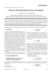
Invited paperOPTO-ELECTRONICS REVIEW 10(4), 237–242 (2002)<strong>Advances</strong> <strong>in</strong> <strong>MOCVD</strong> <strong>technology</strong> <strong>for</strong> <strong>research</strong>, <strong>development</strong> <strong>and</strong> massproduction of compound semiconductor devicesK. CHRISTIANSEN, M. LUENENBUERGER, B. SCHINELLER, M. HEUKEN, <strong>and</strong> H. JUERGENSENAIXTRON AG * , Kackertstr. 15-17, D-52072 Aachen, GermanyThe recent years have seen a cont<strong>in</strong>uous transfer of excit<strong>in</strong>g new technologies from basic <strong>research</strong> <strong>in</strong>stitutions to high yieldmass production <strong>and</strong> <strong>in</strong>to our everyday lives. Devices made from novel semiconductor compounds can be found <strong>in</strong> productsrang<strong>in</strong>g from consumer electronics to high speed backbone communication networks. This <strong>in</strong>cludes high power <strong>in</strong>frared laserdiodes <strong>for</strong> glass fiber applications, ultra-high brightness light emitt<strong>in</strong>g diodes <strong>for</strong> display <strong>and</strong> light<strong>in</strong>g, high power blue <strong>and</strong>UV laser diodes <strong>for</strong> mass storage as well as all types of transistors made from silicon, III-V compounds <strong>and</strong> silicon-carbide.To facilitate the easy <strong>and</strong> straigt<strong>for</strong>ward transfer from <strong>research</strong> scale experimental setups to large area substrates <strong>for</strong> massproduction AIXTRON offers the whole scale of epitaxy solutions from s<strong>in</strong>gle wafer systems to large scale production mach<strong>in</strong>es<strong>for</strong> up to 95 wafers. The easy configurability of the systems <strong>in</strong> terms of up-scal<strong>in</strong>g of wafer sizes up to 7´6 <strong>in</strong>ch <strong>for</strong>phosphides <strong>and</strong> arsenides <strong>and</strong> up to 8´4 <strong>in</strong>ch <strong>for</strong> nitride materials <strong>in</strong> concurrence with easy ma<strong>in</strong>tenance, highreproducibility <strong>and</strong> high uni<strong>for</strong>mity across the wafer <strong>and</strong> from wafer to wafer make the AIXTRON systems the ideal solution<strong>for</strong> mass production. The growth pr<strong>in</strong>ciple common to all AIXTRON <strong>MOCVD</strong> systems allows the easy up-scal<strong>in</strong>g of establishedprocesses to larger configurations, even from s<strong>in</strong>gle wafer AIX 200 systems to production type Planetary Reactors ® .Add-ons like <strong>in</strong>-situ monitor<strong>in</strong>g of the growth process by reflectometry (EpiTune ® I <strong>and</strong> EpiTune ® II) or Reflectance AnisotropySpectroscopy (Epi-RAS ® ) help <strong>in</strong> a considerable reduction of the <strong>development</strong> time <strong>and</strong> costs, hence improv<strong>in</strong>g <strong>in</strong>novationcycles <strong>and</strong> the time-to-market of novel devices s<strong>in</strong>ce the growth of the material can be monitored <strong>in</strong> real time.Keywords: <strong>MOCVD</strong> technique, dop<strong>in</strong>g uni<strong>for</strong>mity, <strong>in</strong>-situ charactrization, GaN, AlGaAs, AlGaInP.1. IntroductionIndustry <strong>for</strong>ecasts predict a steady growth of the compoundsemiconductor market due to a variety of applications accessibleby these material systems. The worldwide optoelectroniccomponents sector with data transmission <strong>and</strong> datastorage applications <strong>and</strong> the light emitt<strong>in</strong>g diode segmentwith predicted growth rates of up to 40% <strong>and</strong> over 24%, respectively,account <strong>for</strong> the lion’s share of this total predictedgrowth [1,2,3]. In- <strong>and</strong> outdoor light<strong>in</strong>g, large scalevideo displays, <strong>in</strong>frared telecommunication <strong>for</strong> backbonedata networks, mobile communication <strong>and</strong> data storage areamong the applications rely<strong>in</strong>g on cheap, efficient <strong>and</strong> reproducibledevices fabricated from III-V compounds.Equipment manufacturers must, there<strong>for</strong>e, provide the <strong>in</strong>dustrywith the tools it requires to deliver these dem<strong>and</strong>s tocompete <strong>in</strong> this <strong>in</strong>terest<strong>in</strong>g <strong>and</strong> fast grow<strong>in</strong>g market.AIXTRON as the world‘s lead<strong>in</strong>g manufacturer ofmetal-organic chemical vapor deposition (<strong>MOCVD</strong>) equipmentmeets these dem<strong>and</strong>s by supply<strong>in</strong>g the <strong>in</strong>dustry withmultiwafer Planetary Reactors ® with ever higher productivity.The productivity of an <strong>MOCVD</strong> system is primarily* e-mail: <strong>in</strong>fo@aixtron.comphone: +49-241-8909-0, fax: +49-241-8909-40driven by the depositable wafer area, the uni<strong>for</strong>mity acrossthe wafers, their reproducibility from wafer to wafer <strong>and</strong>run to run, <strong>and</strong> the number of runs per day.This paper elaborates on the achieved results <strong>for</strong> thematerial families of (Al)GaAs, GaInP, AlInGaP <strong>and</strong>(In)GaN, with a focus on electrical, optical <strong>and</strong> structuraldata. Van-der-Pauw Hall-effect measurements, non-contactsheet resistance mapp<strong>in</strong>g, room temperature photolum<strong>in</strong>esence(PL) mapp<strong>in</strong>g <strong>and</strong> high resolution X-ray diffraction(XRD) were used to quantify the results.2. Experimental <strong>and</strong> results2.1. Phosphorus <strong>and</strong> arsenic conta<strong>in</strong><strong>in</strong>g materialsGaAs-based HEMT <strong>and</strong> HBT target the market of 10GBit/s amplifiers <strong>for</strong> metro area networks (MAN). The layoutof such amplifiers requires the monolithic <strong>in</strong>tegrationof active <strong>and</strong> passive elements requir<strong>in</strong>g large area growthtechnologies with a focus on yield, reliability <strong>and</strong> uni<strong>for</strong>mity.To meet these dem<strong>and</strong>s we have developed theAIXTRON Planetary Reactor ® , which, <strong>in</strong> its 5´4 <strong>in</strong>ch configuration,is already qualified <strong>for</strong> the production ofInP-based HBTs <strong>for</strong> 40 GBit/s backbone data transmissionamplifiers. To <strong>in</strong>crease the wafer area depositable per runthe 7´6 <strong>in</strong>ch configuration was built.Opto-Electron. Rev., 10, no. 4, 2002 K. Christiansen 237
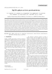
<strong>Advances</strong> <strong>in</strong> <strong>MOCVD</strong> <strong>technology</strong> <strong>for</strong> <strong>research</strong>, <strong>development</strong> <strong>and</strong> mass production of compound semiconductor devicesFig. 1. Layout of the AIX 2600G3 susceptor <strong>in</strong> the 5´6 <strong>in</strong>ch (left)<strong>and</strong> 7´6 <strong>in</strong>ch (right) configurations.Figure 1 shows a schematic of the susceptor of the AIX2600G3 <strong>in</strong> the 5´6 <strong>in</strong>ch (left) <strong>and</strong> the 7´6 <strong>in</strong>ch (right) configurations.Figure 2 shows a correspond<strong>in</strong>g photo of thereactor chamber. The gases enter the reactor chamberthrough the central <strong>in</strong>let <strong>in</strong> the reactor lid (not visible <strong>in</strong> thephoto) <strong>and</strong> stream radially outward across the depositionzone. The susceptor is heated by RF <strong>in</strong>duction heat<strong>in</strong>g frombelow <strong>and</strong> rotates at rotation frequencies of typically10 rpm. In addition the wafer discs are rotat<strong>in</strong>g utiliz<strong>in</strong>gAIXTRON’s patented Gas Foil Rotation ® technique. Thisdouble rotation <strong>in</strong>sures highest uni<strong>for</strong>mities.To assess the per<strong>for</strong>mance of the system <strong>for</strong> the growthof p-HEMT <strong>and</strong> HBT structures we have <strong>in</strong>vestigated thep- <strong>and</strong> n-type dop<strong>in</strong>g uni<strong>for</strong>mities of GaAs, <strong>and</strong> the n-typedop<strong>in</strong>g of Al 0.3 Ga 0.7 As <strong>and</strong> GaInP. Figure 3 shows theachieved on-wafer dop<strong>in</strong>g uni<strong>for</strong>mities of GaAs on 6 <strong>in</strong>chof 1.24% <strong>and</strong> 1.1% st<strong>and</strong>ard deviation of the sheet resistanceat carrier densities of 8´10 17 cm –3 <strong>and</strong> 3´10 19 cm –3<strong>for</strong> n- <strong>and</strong> p-type, respectively. The correspond<strong>in</strong>g wafer towafer reproducibilites <strong>in</strong> the same run were of ±0.4% <strong>and</strong>Fig. 2. Photo of the reactor chamber of the AIX 2600G3 <strong>in</strong> the 7´6<strong>in</strong>ch configuration.±0.7%, respectively. In analogous experiments n-type dop<strong>in</strong>glevels of 1´10 17 cm –3 (s onW = 1.26%) <strong>and</strong> 1´10 18 cm –3(s onW = 3%) were achieved <strong>for</strong> Al 0.3 Ga 0.7 As <strong>and</strong> GaInP, respectively.These values satisfy the dem<strong>and</strong>s of p-HEMT<strong>and</strong> HBT applications <strong>and</strong> <strong>in</strong>sure excellent yield <strong>in</strong> massproduction on large wafers.Besides the need <strong>for</strong> excellent electrical data, the massproduction of semiconductor devices dem<strong>and</strong>s the controlof composition <strong>and</strong> thickness. Figure 4 shows the thicknessuni<strong>for</strong>mity of a2µmthick Al 0.3 Ga 0.7 As layer on a 6 <strong>in</strong>chGaAs wafer. The st<strong>and</strong>ard deviation was determ<strong>in</strong>ed to be0.17%.Low cost of ownership is dependent on the efficient utilizationof the precursor materials, notably the metalorganicsources. By tun<strong>in</strong>g of the total carrier gas flow thegrowth maximum of the semiconductor can be neatly tunedradially <strong>in</strong> the reactor chamber. To <strong>in</strong>vestigate the dependenceof the growth rate on the position along the susceptorFig. 3. Dop<strong>in</strong>g uni<strong>for</strong>mities on 6 <strong>in</strong>ch <strong>for</strong> n-type GaAs (left) <strong>and</strong> p-type GaAs (right). At 8´10 17 cm –3 (n-type) <strong>and</strong> 3´10 19 cm –3 (p-type)st<strong>and</strong>ard deviations of the carrier concentration of 1.24% <strong>and</strong> 1.1% were achieved, respectively. The uni<strong>for</strong>mity from wafer to wafer waswith<strong>in</strong> ±0.4% <strong>and</strong> ±0.7% <strong>for</strong> n- <strong>and</strong> p-type material, respectively.238 Opto-Electron. Rev., 10, no. 4, 2002 © 2002 COSiW SEP, Warsaw
Invited paperFig. 4. Thickness uni<strong>for</strong>mity of 6 <strong>in</strong>ch Al 0.3 Ga 0.7 As. This 2 µmthick layer exhibited a st<strong>and</strong>ard deviation of 0.17%.radius AlAs/GaAs distributed Bragg reflectors (DBR) weregrown with one 6 <strong>in</strong>ch disc <strong>in</strong>tentionally stopped. High resolutionX-ray spectra were recorded across the diameter ofthe 6 <strong>in</strong>ch wafers which showed a decrease of the satellitespac<strong>in</strong>g. This <strong>in</strong>dicates a gradient <strong>in</strong> layer thickness, hencegrowth rate, from the center to the rim of the susceptor.This gradient can be utilized to tune the thickness uni<strong>for</strong>mityby rotat<strong>in</strong>g the discs through the depletion gradient. InXRD profiles of a rotated 6 <strong>in</strong>ch wafer from the same runthe fr<strong>in</strong>ges are equidistant across the wafer diameter <strong>in</strong>dicat<strong>in</strong>gan excellent thickness uni<strong>for</strong>mity of the layers. Thewafer appeared green to the unaided eye without any visiblecolor changes <strong>and</strong> <strong>in</strong>homogeneities. Reflectance measurementsshowed an average reflected wavelength of552.4 nm with an overall st<strong>and</strong>ard deviation of 3.1 nm correspond<strong>in</strong>gto 0.5%. The efficiency of the group-III precursorswas found to vary with the carrier gas flow rate from40% up to 54% with the highest values obta<strong>in</strong>ed at the lowend of the carrier gas flow rate range.With the 7´6 <strong>in</strong>ch layout a valueable configuration isadded to the repertoir of AIXTRON’s Planetary Reactor ®concept. The excellent homogeneities <strong>and</strong> reproducibilitiesknown from other configurations offer the device manufacturerthe possibility to exp<strong>and</strong> his production capacity withoutthe need <strong>for</strong> extensive process adaptations.2.2. NitridesInGaN multi-quantum well (MQW) structures are at theheart of todays modern blue-green <strong>and</strong> white emitters. Themarket <strong>for</strong> conventional devices such as blue <strong>and</strong> greenlight emitt<strong>in</strong>g diodes (LED) as well as emerg<strong>in</strong>g applicationslike white light<strong>in</strong>g LEDs <strong>and</strong> blue to ultra-violett lasers,has grown steadily over the past years. Large area outdoordisplays, <strong>in</strong>door light<strong>in</strong>g as replacements <strong>for</strong> <strong>in</strong>c<strong>and</strong>escent<strong>and</strong> flourescent lamps <strong>and</strong> blue-UV lasers <strong>for</strong> datastorage are at the heart of the market. As <strong>for</strong> the phosphides<strong>and</strong> arsenides the dem<strong>and</strong>s <strong>for</strong> higher production capabilities<strong>in</strong>creases with the <strong>in</strong>troduction of larger wafer sizes.To meet these dem<strong>and</strong>s we have <strong>in</strong>troduced the AIX2000/2400/2600G3 HT <strong>MOCVD</strong> system which can be fittedwith the 6´2, 11´2, 5´3, 7´3, 8´4 <strong>and</strong> 24´2 <strong>in</strong>ch configurations.Thus, this system is capable to meet the needsof future applications such as high temperature <strong>and</strong> highfrequency monolithic devices which will dem<strong>and</strong> wafersizes of at least 4 <strong>in</strong>ch.Figure 5 shows a photo of the AIX 2600G3 HT <strong>in</strong> the24´2 <strong>in</strong>ch configuration. To assess the per<strong>for</strong>mance of thesystem we have chosen to <strong>in</strong>vestigate the properties of5 period multi-quantum-well (MQW) structures consist<strong>in</strong>gof InGaN wells <strong>and</strong> GaN barriers emitt<strong>in</strong>g around 470 nmwhich is a prom<strong>in</strong>ent wavelength <strong>for</strong> blue LED applications.The entire quantum well stack was grown at constanttemperature without temperature cycl<strong>in</strong>g between barrier<strong>and</strong> well. Figure 6 shows 24 PL mapp<strong>in</strong>gs of wafers grown <strong>in</strong>the same run <strong>and</strong> their respective position on the susceptor.The InGaN material system is <strong>in</strong>herently sensitive to slightvariations <strong>in</strong> process conditions due to the material’s miscibilitygap which is large <strong>in</strong> the middle of the In/Ga compositionrange. The mean wavelength over all wafers was472 nm with a wafer to wafer st<strong>and</strong>ard deviation of 1.2 nm,or an equivalent of Dl max-m<strong>in</strong> = 4.2 nm, which are excellentvalues fit <strong>for</strong> mass production requirements.Fig. 5. Photo of the reactor chamber of the AIX 2600G3 HT <strong>in</strong> the24´2 <strong>in</strong>ch configuration.Table 1 shows corroborative data <strong>for</strong> the run mentionedabove <strong>and</strong> a second run at around 522 nm. The observed <strong>in</strong>crease<strong>in</strong> spread with <strong>in</strong>creas<strong>in</strong>g wavelength results from<strong>in</strong>creased phase separation <strong>for</strong> material approach<strong>in</strong>g compositions<strong>in</strong> the middle of the miscibility gap.Tab. 1. Typical on-wafer <strong>and</strong> wafer-to-wafer st<strong>and</strong>ard deviationsof the wavelength <strong>for</strong> two different wavelength regimes. Thestructures consisted of 5 period multi quantum wells.WavelengthOn-wafer std. dev.(typical)W2W spread of meanvalue472.2 nm 1.6 nm ±2.1 nm522.3 nm 1.7 nm ±4.2 nmOpto-Electron. Rev., 10, no. 4, 2002 K. Christiansen 239
<strong>Advances</strong> <strong>in</strong> <strong>MOCVD</strong> <strong>technology</strong> <strong>for</strong> <strong>research</strong>, <strong>development</strong> <strong>and</strong> mass production of compound semiconductor devicesFig. 6. PL maps of InGaN MQW structures at 472 nm grown <strong>in</strong> thesame run as a function of wafer position on the susceptor. Them<strong>in</strong>imum to maximum wavelength spread was 4.2 nm whichcorresponds to a st<strong>and</strong>ard deviation of 1.2 nm.Optically pumped laser emission was <strong>in</strong>vestigated onsimilar MQW structures with differ<strong>in</strong>g In-concentrations.The highest achieved las<strong>in</strong>g wavelength was measured tobe 469.5 nm at room temperature with a las<strong>in</strong>g threshold of900 kW/cm 2 [4–6].One additional important aspect of production yield isthe reproducibility of the growth runs as a function of time.To assess the AIX 2600G3 HT’s stability we have grown7 consecutive runs us<strong>in</strong>g the same unchanged growth recipe.No etch<strong>in</strong>g or bakeout procedures were per<strong>for</strong>med <strong>in</strong>between the <strong>in</strong>dividual runs. The wavelength stability ofthe MQW structures was measured us<strong>in</strong>g photolum<strong>in</strong>escencemapp<strong>in</strong>g. The evaluation yielded at mean wavelength of461.8 nm <strong>and</strong> a spread of 3.9 nm from the maximum to them<strong>in</strong>imum wavelength. The distribution of the wavelengthsas a function of the growth run was found to be statistical,hence <strong>in</strong>dicat<strong>in</strong>g no drift of the system.These results show that the AIX 2600G3 HT system isa tool that satisfies the <strong>in</strong>dustry’s requirements <strong>for</strong> massFig. 7. Schematic of the pr<strong>in</strong>ciple of an RAS measurement.240 Opto-Electron. Rev., 10, no. 4, 2002 © 2002 COSiW SEP, Warsaw
Invited paperFig. 8. In-situ monitor<strong>in</strong>g by EpiRAS ® <strong>in</strong> the example of a HBT layer structure (from ).production <strong>MOCVD</strong> systems <strong>in</strong> the fast <strong>and</strong> excit<strong>in</strong>g fieldof group-III nitrides.2.3. In-situ characterizationIn-situ characterization, the ability to directly observe thegrowth of the semiconductor material <strong>in</strong> the reactor chamber,has been well known <strong>in</strong> molecular beam epitaxy(MBE) <strong>in</strong> the past. However, powerful methods of <strong>in</strong>-situcharacterization have found their way <strong>in</strong>to more productionoriented growth methods like MOVPE. We developed different<strong>in</strong>-situ methods that both deliver valuable <strong>in</strong><strong>for</strong>mationon the growth of the layers <strong>and</strong>, there<strong>for</strong>e, speed up theoptimization loops <strong>in</strong> the <strong>development</strong> of MOVPE processes.All methods can be used <strong>in</strong> small scale horizontaltube reactors as well as <strong>in</strong> large production type multiwafersystems. In the latter case each wafer can be measured <strong>and</strong>the obta<strong>in</strong>ed results can be assigned. This allows <strong>for</strong> a diagnosticof the wafers even be<strong>for</strong>e the growth run is f<strong>in</strong>ished.Reflection anisotropy spectroscopy (RAS, EpiRAS ® )measures the difference between the normal-<strong>in</strong>cidence opticalreflectance of light polarized along the two pr<strong>in</strong>cipal axes<strong>in</strong> the surface as a function of photon energy (Fig. 7). S<strong>in</strong>cemany semiconductors are cubic <strong>and</strong> there<strong>for</strong>e optically isotropic,only the anisotropy of the uppermost atomic layerswill result <strong>in</strong> a change of polarisation. There<strong>for</strong>e, the methodis sensitive to the properties of the wafer’s growth front <strong>and</strong>can give valuable <strong>in</strong><strong>for</strong>mation about the dop<strong>in</strong>g concentrations,the composition <strong>and</strong> the crystall<strong>in</strong>e quality of the material.Figure 8 shows a false colour plot of the RAS signal<strong>for</strong> a GaAs/GaInP HBT run. The different layers are clearlyidentifiable <strong>in</strong> the time resolved false colour plot. Thegrowth specialist can now utilize his database to speed upthe optimization process <strong>for</strong> the device fabrication.In the case of a material system with clearly different<strong>in</strong>dices of refraction between an underly<strong>in</strong>g layer <strong>and</strong> thelayer to be probed, time-resolved Fabry-Perot likereflectance is utilized to determ<strong>in</strong>e the growth-rate <strong>and</strong> thecrystall<strong>in</strong>e quality of the grow<strong>in</strong>g wafers. These methods,EpiTune ® I <strong>and</strong> EpiTune ® II, can be applied <strong>in</strong> the case ofnitride semiconductor structures where a step <strong>in</strong> refractive<strong>in</strong>dices is present at the <strong>in</strong>terface between the grow<strong>in</strong>g devicestructure <strong>and</strong> the sapphire wafer or <strong>in</strong> selected phosphorus<strong>and</strong> arsenic conta<strong>in</strong><strong>in</strong>g device structures. In addition,features <strong>in</strong> the traces at the beg<strong>in</strong>n<strong>in</strong>g of the layergrowth can be dist<strong>in</strong>guished by the experienced process eng<strong>in</strong>eer,thus speed<strong>in</strong>g up time to market <strong>for</strong> new processes<strong>and</strong> devices. Figure 9 exhibits such a trace <strong>for</strong> the case ofan InGaN MQW structure as described above. The differentsteps like nucleation, anneal, buffer <strong>and</strong> MQW growthcan be clearly dist<strong>in</strong>guished.In addition to the sole measurement of the reflectivityas a function of time, EpiTune ® II offers the possibility tomeasure the emissivity corrected temperature <strong>for</strong> each wafer.A high repetition rate of the pyrometric temperaturemeasurement <strong>and</strong> the prob<strong>in</strong>g of the reflectivity through thesame optical path facilitate an accurate determ<strong>in</strong>ation of theemissivity corrected temperature, s<strong>in</strong>ce pyrometry <strong>and</strong>Fig. 9. In-situ reflectometry <strong>for</strong> an InGaN MQW growth run.Opto-Electron. Rev., 10, no. 4, 2002 K. Christiansen 241
<strong>Advances</strong> <strong>in</strong> <strong>MOCVD</strong> <strong>technology</strong> <strong>for</strong> <strong>research</strong>, <strong>development</strong> <strong>and</strong> mass production of compound semiconductor devicesreflectometry are practically per<strong>for</strong>med on the same po<strong>in</strong>ton the wafer.In summary, these <strong>in</strong>-situ tools offer the possibility <strong>for</strong>efficient process <strong>development</strong> <strong>and</strong> monitor<strong>in</strong>g, s<strong>in</strong>ce thematerial can be observed directly dur<strong>in</strong>g the growth process.In process <strong>development</strong> the f<strong>in</strong>e tun<strong>in</strong>g of process parameterscan be directly evaluated <strong>in</strong> the observed spectra<strong>and</strong> traces sav<strong>in</strong>g cost <strong>and</strong> time <strong>and</strong> guarantee<strong>in</strong>g a quicktime-to-market of new devices. In addition, a quick <strong>and</strong> reliablemethod of yield evaluation <strong>and</strong> process stability controlcan be established <strong>in</strong> the fab, s<strong>in</strong>ce the <strong>in</strong>-situ measurementresults are stored <strong>for</strong> each wafer <strong>in</strong>dividually, allow<strong>in</strong>gan easy tracebility of device results to epitaxial growth.This enhances the accuracy of yield prediction even be<strong>for</strong>ea wafer is processed <strong>in</strong>to devices, thus lower<strong>in</strong>g productioncosts <strong>and</strong> <strong>in</strong>creas<strong>in</strong>g a stable device production output.3. ConclusionMOVPE has established itself as the method of choice <strong>for</strong>mass production of modern compound semiconductor devices.The easy transferrability of process conditions fromtool to tool, the h<strong>and</strong>s-on control of processes by directmonitor<strong>in</strong>g of the grow<strong>in</strong>g layer, the low cost of ownership,the high yield <strong>and</strong> the high volume throughput that thePlanetary Reactor ® MOVPE growth technique offers areamong the ma<strong>in</strong> decid<strong>in</strong>g factors <strong>for</strong> the choice of PlanetaryReactor ® MOVPE <strong>for</strong> the <strong>in</strong>dustry’s production capabilities.References1 ElectroniCast, Compound Semiconductor Magaz<strong>in</strong>e 8(2),26, (2002).2 Accord<strong>in</strong>g to Investec Inc., Equity Research, July 16, 20023 Strategies Unlimited, presented at Strategies <strong>in</strong> Light 2002,Feb. 6-8, 2002.4 G.P. Yablonskii, E.V. Lutsenko, V.N. Pavlovskii, I.P.Marko, A.L. Gurskii, V.Z. Zubialevich, O. Schoen, H.Protzmann, M. Luenenbuerger, B. Sch<strong>in</strong>eller, <strong>and</strong> M.Heuken, Phys. Stat. Sol. (a) 188, 79 (2001).5 G.P. Yablonskii, E.V. Lutsenko, V.N. Pavlovskii,I.P. Marko, A.L. Gurskii, V.Z. Zubialevich, A.V. Mudryi,O. Schön, H. Protzmann, M. Luenenbuerger, B. Sch<strong>in</strong>eller,M. Heuken, H. Kalisch, <strong>and</strong> K. Heime, Appl. Phys. Lett. 79,1953 (2001).6 B. Sch<strong>in</strong>eller, H. Protzmann, M. Luenenbuerger, G.Gerstenbr<strong>and</strong>t, M. Heuken, G.P. Yablonskii, A.V. Mudryi,E.V. Lutsenko, V.N. Pavlovskii, <strong>and</strong> V.Z. Zubialevich, presentedat the Inter. Conf. on the Physics of Semicond.(ICPS), Ed<strong>in</strong>burgh, Scotl<strong>and</strong>.7 B. Sch<strong>in</strong>eller, H. Protzmann, M. Luenenbuerger, G.P.Yablonskii, E.V. Lutsenko, V.N. Pavlovskii, V.Z. Zubialevich,M. Heuken, <strong>and</strong> H. Juergensen, presented at the Inter.Conf. on Nitride Semiconductors 4 (ICNS 4), Denver, Colorado,USA.8 B. Sch<strong>in</strong>eller, H. Protzmann, M. Luenenbuerger, G.Gerstenbr<strong>and</strong>t, M. Heuken, E.V. Lutsenko, V.N. Pavlovskii,V.Z. Zybialevich, <strong>and</strong> G.P. Yablonskii, presented atEXMATEC 2002, Budapest, Hungary.9 J.-T. Zettler, K. Haberl<strong>and</strong>, M. Zorn, M. Pristovsek, W.Richter, P. Kurpas, <strong>and</strong> M. Weyers, J. Crystal Growth 195,151 (1998).242 Opto-Electron. Rev., 10, no. 4, 2002 © 2002 COSiW SEP, Warsaw