Download (PDF 3.9 MB) - Bosch Thermotechnology
Download (PDF 3.9 MB) - Bosch Thermotechnology
Download (PDF 3.9 MB) - Bosch Thermotechnology

Create successful ePaper yourself
Turn your PDF publications into a flip-book with our unique Google optimized e-Paper software.
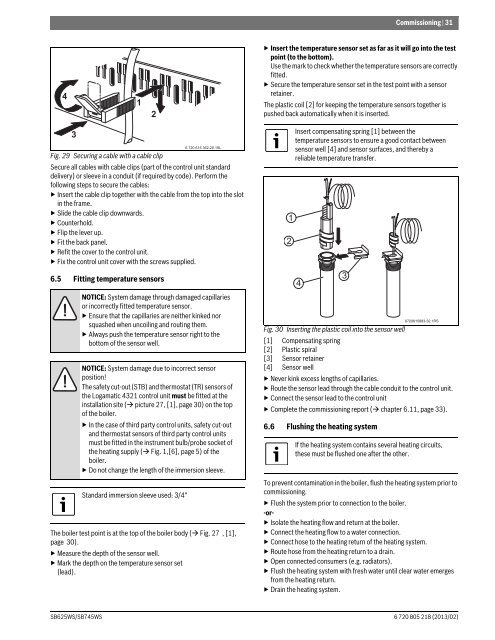
Commissioning | 31▶ Insert the temperature sensor set as far as it will go into the testpoint (to the bottom).Use the mark to check whether the temperature sensors are correctlyfitted.▶ Secure the temperature sensor set in the test point with a sensorretainer.The plastic coil [2] for keeping the temperature sensors together ispushed back automatically when it is inserted.Fig. 29 Securing a cable with a cable clipSecure all cables with cable clips (part of the control unit standarddelivery) or sleeve in a conduit (if required by code). Perform thefollowing steps to secure the cables:▶ Insert the cable clip together with the cable from the top into the slotin the frame.▶ Slide the cable clip downwards.▶Counterhold.▶ Flip the lever up.▶ Fit the back panel.▶ Refit the cover to the control unit.▶ Fix the control unit cover with the screws supplied.6.5 Fitting temperature sensorsNOTICE: System damage through damaged capillariesor incorrectly fitted temperature sensor.▶ Ensure that the capillaries are neither kinked norsquashed when uncoiling and routing them.▶ Always push the temperature sensor right to thebottom of the sensor well.NOTICE: System damage due to incorrect sensorposition!The safety cut-out (STB) and thermostat (TR) sensors ofthe Logamatic 4321 control unit must be fitted at theinstallation site ( picture 27, [1], page 30) on the topof the boiler.▶ In the case of third party control units, safety cut-outand thermostat sensors of third party control unitsmust be fitted in the instrument bulb/probe socket ofthe heating supply ( Fig. 1,[6], page 5) of theboiler.▶ Do not change the length of the immersion sleeve.Standard immersion sleeve used: 3/4"6 720 615 362-20.1SLThe boiler test point is at the top of the boiler body ( Fig. 27 , [1],page 30).▶ Measure the depth of the sensor well.▶ Mark the depth on the temperature sensor set(lead).12Insert compensating spring [1] between thetemperature sensors to ensure a good contact betweensensor well [4] and sensor surfaces, and thereby areliable temperature transfer.4Fig. 30 Inserting the plastic coil into the sensor well[1] Compensating spring[2] Plastic spiral[3] Sensor retainer[4] Sensor well▶ Never kink excess lengths of capillaries.▶ Route the sensor lead through the cable conduit to the control unit.▶ Connect the sensor lead to the control unit▶ Complete the commissioning report ( chapter 6.11, page 33).6.6 Flushing the heating system36720615883-32.1RSIf the heating system contains several heating circuits,these must be flushed one after the other.To prevent contamination in the boiler, flush the heating system prior tocommissioning.▶ Flush the system prior to connection to the boiler.-or-▶ Isolate the heating flow and return at the boiler.▶ Connect the heating flow to a water connection.▶ Connect hose to the heating return of the heating system.▶ Route hose from the heating return to a drain.▶ Open connected consumers (e.g. radiators).▶ Flush the heating system with fresh water until clear water emergesfrom the heating return.▶ Drain the heating system.SB625WS/SB745WS6 720 805 218 (2013/02)