CHALLENGER'S LOST LESSONS - ER - NASA
CHALLENGER'S LOST LESSONS - ER - NASA
CHALLENGER'S LOST LESSONS - ER - NASA

Create successful ePaper yourself
Turn your PDF publications into a flip-book with our unique Google optimized e-Paper software.
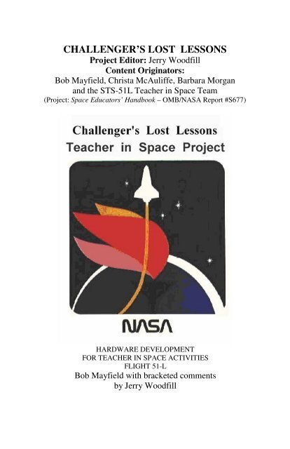
CHALLENG<strong>ER</strong>’S <strong>LOST</strong> <strong>LESSONS</strong>Project Editor: Jerry WoodfillContent Originators:Bob Mayfield, Christa McAuliffe, Barbara Morganand the STS-51L Teacher in Space Team(Project: Space Educators’ Handbook – OMB/<strong>NASA</strong> Report #S677)HARDWARE DEVELOPMENTFOR TEACH<strong>ER</strong> IN SPACE ACTIVITIESFLIGHT 51-LBob Mayfield with bracketed commentsby Jerry Woodfill
2TABLE OF CONTENTSBackground 3Hardware Development for Lost Lessons 6Challenger’s Lost Live Lessons 21Editor’s Comments 23The Lost Hydroponics Chamber Lesson 25The Lost Magnetic Chamber Lesson 34The Lost Newton’s Laws Lesson 49The Lost Effervescence Lesson 59The Lost Chromatography Lesson 63The Lost Simple Machines Lesson 69The First Lost Live Lesson (Ultimate Field Trip) 78The Second Lost Live Lesson 84Instructions on using the CDROM and DVD 97
3CHALLENG<strong>ER</strong>’S <strong>LOST</strong> <strong>LESSONS</strong>[Background: In 2007, the space shuttle mission STS-118 launchedwith Christa McAuliffe’s backup Teacher in Space candidate BarbaraMorgan. Though more than a score of years after the loss ofChallenger’s crew, STS-118 was a reminder of the morning ofJanuary 28, 1986. That week Christa McAuliffe planned to performboth live and filmed science lessons. These lost lessons, preparedfor the nation and world’s school children, were never done. Thisproject delves into those undone educational activities. Indeed, afterstudying its content, all will appreciate <strong>NASA</strong>’s, Christa’s andBarbara’s efforts as well as Bob Mayfield’s in carefully researching,preparing and training for the performance of the six “Challenger lostlessons.” Though lost in the sense that they perished withChallenger and her crew, recounting, redoing, and examining themis, in a sense, a resurrection. As such, they become a tribute toChrista and her courageous crewmates, the CHALLENG<strong>ER</strong> SEVEN.Chronology: The happenstance of this editor discovering a copy ofBob Mayfield’s, discussion of the six planned on orbit sciencedemonstrations led to the project. Mayfield was a <strong>NASA</strong>Educational Specialist during the 1980s. His work greatly impressedthis author, a spacecraft design engineer. Fascination focused on theextent of the science and engineering performed in the conception,preliminary planning, and earth-based exercises of the lost sixlessons. Added to this were the mock-up planning practices andzero-g demonstrations of the lessons by Christa, Barbara, Bob, andthe <strong>NASA</strong> team.Mayfield’s narrative descriptions of the apparatus involved in each ofthe six science experiments were excellent. All were written in thebest descriptive technical writing prose. However, not being able toview the described hardware made understanding difficult. Thepaper did not include sketches. Able assistance from <strong>NASA</strong> JSCmedia sources, Mike Gentry, Celeste Wicks and Dr. Jennifer Ross-
4Nazzal, the JSC Historian, came to the editor’s rescue. Theyprovided both excellent photos and videos of Christa, Barbara, andBob going through the scripted on-orbit performance of the lost sixlessons. Additionally, an internet search found the <strong>NASA</strong> Educators’Guide for the pair of on-orbit live experiments. The ChallengerCenter website, founded in honor of Christa and her fellowcrewmates, had a .pdf copy of the lesson plan. Unfortunately, theplan dealt only with the pair of live lessons. The proposed six onorbitfilmed demonstrations were not addressed.Approach: The basis for the project is Mayfield’s article on thehardware development of the six lost lessons. To its content, thiseditor adds photos, video clips, and supporting narrativesupplementing Mayfield’s observations and writings. Theseadditions are set off in brackets, [….], to distinguish them fromMayfield’s work for the JSC Education Office. The editor, using thevideos and Mayfield’s descriptions, has authored classroom versionsof each of the six lost lessons. Often included are sketches andimages of the apparatus related to the experiments. To assist theclassroom teacher in performing each of the lessons, the scriptedexperiments are included in the project. They are attached to the bodyof Mayfield’s work and accessed on the CDROM via holding downthe CTRL key and clicking on the individual items listed above,“hydroponics, magnetism,…etc.”. Each includes a materials list,precautionary comments where appropriate, setup, as well as step bystep instructions for performing each experiment.The <strong>NASA</strong> 1985 publication TEACH<strong>ER</strong> IN SPACE PROJECT Guideexplains why virtually no follow on material was prepared forperforming the six lost lessons in the classroom. The Guide statesregarding the plans for the six filmed lessons:Filmed Activities: In addition to live lessons, McAuliffe willconduct a number of demonstrations during the flight. These filmedactivities (the six lost lessons) will be used as part of severaleducational packages to be prepared and distributed after theMission.”
5Obviously, because of the loss of Challenger, no subsequenteducational packages were prepared and distributed after theMission. Therefore, no supporting information was found in <strong>NASA</strong>literature so that the editor has prepared substitute instructionalmaterial (packages), i.e., six substitute exercises replicating Christa’ssix lost lessons planned for the Challenger Mission, STS-51L.Likewise, no follow-up to the pair of Live Lessons ensued. For thatreason, this project treats them in the same fashion as the lost filmeddemonstrations. However, Mayfield’s paper devoted much lessdiscussion to the live lessons. Nevertheless, the archived videocontent gave them as much attention as those planned for filmingaboard Challenger. Therefore, they are treated in equal detail in theconcluding chapters of this project.Because much understanding of the lost lessons comes from viewingChrista and others in video clips, the project is recorded on aCDROM able to display Christa’s, Barbara’s, and Mayfield’s actions,words, and findings. In this sense, it becomes a worthy substitute forChrista’s planned on orbit filming of the six lost lessons. Using theCDROM, educators can replicate that which Christa was not able toshare from orbit. But, fortunately, her wonderful teaching gift andspirit are captured on video tape. Though performed both on earthand in <strong>NASA</strong>’s zero-g aircraft rather than on orbit, Christa’s remarksand actions in training for the six experiments accomplish most ofher lesson plans.While more than a score of years have passed, her often quotedremark is once more validated through this project, “I touch thefuture, I teach”. Students experiencing the six lost lessons will fulfillChrista’s prophetic words. They are the future touched by Christa’steaching gift. May all who participate in this project know the samewarmth and admiration for Christa as those who selected her as<strong>NASA</strong>’s first teacher in space.] JRW – Houston - 2007
6HARDWARE DEVELOPMENTFOR TEACH<strong>ER</strong> IN SPACE ACTIVITIESFLIGHT 51-LBy Bob MayfieldHardware design and development began at JohnsonSpace Center in August 1985. Although a number of peoplecontributed to the proceeds, a talented team of engineers fromPan American Engineering and the personnel in the shops atJohnson Space Center comprised the backbone of the process.The Teacher in Space Project (TISP) involves sixactivities which will be filmed and photographed during themission and two live lessons aired on flight day 6. The sixactivities are listed below in the order in which they will beconducted. A discussion of some of the rationale for thehardware design follows: [The following are henceforthidentified as the lost six.]HYDROPONICSMAGNETISMNEWTON’S LAWSEFF<strong>ER</strong>VESCENCECHROMATOGRAPHYSIMPLE MACHINESBefore discussing each activity, it is probably appropriate torelate some of the general constraints that applied to the payload ingeneral. First, it had to fit within the confines of one mid-decklocker (approximately 17"x14"x22"). It had to pass off-gas tolerancecriteria. This eliminated or restricted the use of many plastics,metals, adhesives, and liquids. Obviously, it had to be safe and notinterfere with the operations of the Orbiter's systems. Alsoconsidered was the flammability of the materials independently and
7collectively. Other constraints were established by the perceivedgoals of the project. For instance, it was important that teachers inthe classroom would be able to closely duplicate the equipment andconduct demonstrations to be used as a comparison of the behaviorof phenomena on Earth and on-orbit. It was believed that highlyexotic hardware would inhibit the involvement of some teachers andstudent groups. The range of age levels had to be considered. Theaction, interaction, or reaction of components had to be clear in orderto be filmed and photographed.Finally,the number and variety of the activities, plus the equipment tosupport the live lessons precluded the possibility for the educationstaff to develop viable quantitative science experiments of eachactivity in the time allotted to produce the hardware. Therefore, theactivities had to be considered qualitative demonstrations.HYDROPONICSThe goal of the hydroponics activity was to demonstrate apossible procedure that might be used on the Space Station and infuture space endeavors to provide nutrient requirements in a closedenvironment in microgravity. The objective was to demonstrate theprocesses related to growing plants in microgravity.The lesson plan called for two white beans to be germinatedper day beginning 7 days prior to launching. One plant from eachpair would have been selected for flight, contained in its own closedhydroponics system.Several problems emerged. White beans take several days togerminate. They produce large plants quickly after emerging. Theabsence of good light for plant growth on the Orbiter would haveaggravated the latter problem by causing the plant to be "leggy" orelongated. There would not be room in the locker to accommodateadequate containers. Mung beans had better characteristics and hadbeen flown on a previous mission, providing some baselineinformation. The number of plants was reduced to six due topayload volume constraints, and it was decided to use three seedlings2 days old and three newly germinating seeds to reduce the overalltime involvement by ground support staff with this single activity.
8Hydroponics in Space LessonAboard the Zero-G Aircraft, Christa Applies Misting to Chamber 6which will hold a Mung BeanAnother major problem was that of providing a substrate forthe plants that would allow for growth while keeping the fertilizerfluid where it belonged. A number of ideas were tested with the helpof volunteers such as Cheryl Barnard, an undergraduate student atthe University of Houston, and John St. John, an eighth grade studentfrom Friendswood, Texas, The final design consists of a 1/2-inchlayer of polyester fiber sandwiched between two lexan rings. Nylonmesh was glued to the upper side of the bottom ring to hold the fiber.The rings are separated by two stainless steel tubes 1/2-inch long.Two screws fit through the tubes to hold the platform together. Twolonger screws secure the platform to the top of the 2-inch diametercylinder. The seed is nestled into the fiber. This configuration wasaccepted for its relatively simple design, keeping in mind the factthat to be cost effective on a large scale, such as in the Space Station,the simplest workable system would be desirable.
9Hydroponics ChamberAnother aspect of this activity is the root misting apparatus incylinder number six. This idea was stimulated by experiments at theEpcot Center. The roots of the plant in this cylinder will be mistedonce a day. If this plant remains as healthy as the others, perhapssuch a weight saving system could be employed on a large scale inthe Space Station.Close View of Hydroponics Experiment Apparatus
10MAGNETISMThe goal of the magnetism activity was to understand the roleof magnetic lines of force in the space environment. The objectiveswere to photograph and observe demonstrations of magnetism inspace, and to photograph and observe lines of magnetic force in threedimensions in a microgravity environment.A compass and bar magnet readily procured from a teachersupply store were selected to demonstrate that magnetism certainly isa force in microgravity. The magnet had to be stripped of its platingmaterial and nickel plated to make it pass off-gas criteria.Magnetism Experiment Ground PracticeA box made of aluminum or some other nonferrous material,holding iron filings, and covered by a transparent top was proposedas a means of demonstrating lines of magnetic force in twodimensions. It soon became clear that a sandwich of two lexanplates separated by a "gasket" of lexan would occupy less volumeand be easier to fabricate. Two tiny holes were drilled in one plate topreclude problems of pressure differential in case of a contingencyEVA causing the cabin pressure to be lowered. Safetyconsiderations precluded the use of iron filings which might have
11been ingested by crewmembers or electronic equipment ifaccidentally released into the cabin. Instead, soft iron wire (balingwire) was cut into lengths 1/8- to 1/4-inch long for use in this and theother magnetism demonstration. These wire pieces had to be coatedwith nickel oxide, soaked in oil, then baked to prevent rusting. Theywere also tumbled with ball bearings 24 hours to remove sharpedges. Some tests were done using #6 steel shot, but the linear wirepieces gave the best results.The original proposal for demonstrating lines of force in 3-Dcalled for a transparent beach ball with an electromagnet suspendedinside. An exhaustive search for a suitable ball was futile. Therefore,a cube was constructed of the same material found covering the drinkcontainers used on the Shuttle. Tests proved its optical qualitieswere acceptable, it was tough, and could be bonded using equipmentat the Johnson Space Center. It was believed that the cubic shapewould cause the least problems with reflections during filming.The electromagnet evolved out of much testing of suitablecore materials, wire sizes and lengths, and battery configurations.The final product consists of 400 feet of copper magnet wire arounda 3-1/2 inch soft iron bolt 1/4-inch in diameter. The resulting magnetis 3/4 inches in diameter. Soft iron does not retain magnetism whenthe power is turned off. Power is supplied by two "AA" batterieswired to a toggle switch with built-in LED, and a variable resistorwith a range of 0-250 ohms.Magnetism Lines of Force in Space Lesson
12Though this electromagnet is not strong enough to hold thewire pieces in 1 g, tests on the KC-135 weightless trainer proved itseffectiveness in microgravity conditions. A more powerful magnetwas not used to preclude interference with the Orbiter systems.An additional problem to be addressed was the introductionof moisture from the breath as the cube was inflated. The resultingcondensation obscured viewing into the bag and caused rusting onthe approximately 4000 wire pieces inside. Solving the problemincluded treating the wire as previously described and putting adesiccant filter in the inflation tube.NEWTON’S LAWSThe goal of this activity was to demonstrate thefundamental laws of motion during weightlessness. Theobjectives were to show the principle of inertia in an orbitingspacecraft; to show the relationship between force, mass, andacceleration; and to show the action-reaction of two differentmasses colliding.To first demonstrate that objects have no apparent weight.in the spacecraft was relatively straightforward; an object wouldbe suspended in midair on a small spring. The spring would notstretch because the object is in free-fall around the Earthtraveling at the same rate as the spacecraft. If the end of thespring were attached to the inside of the craft and a thruster werefired, it would cause the spring to stretch due to the spacecraftchanging velocity with respect to the object.Determining how to demonstrate the objectives was notso straight-forward. Historically, educators have disagreed onmethodology for treating this topic.Add the educated opinion of engineers and technicallyoriented support staff to the realities of the Orbiter environmentand the problem became very complex.There was discussion of using objects such as woodenblocks of different sizes, therefore different mass; except someof the activity called for objects of the same size, yet 1/2 or 1/4
13of the mass of each other. This would have meant findingmaterials whose densities varied with the desired proportions, ormechanically altering (drilling holes) in one of the objects toachieve the desired effect. The wooden block idea soundedplausible until flammability and off-gassing were considered.Using metal blocks was considered and dismissed, rememberingthe criteria of keeping the hardware within the ability of teachersand students to copy as closely as possible. Overall payloadweight (pre-launch) was also considered - metal masses largeenough to be filmed effectively would have been relativelyheavy, even using aluminum. Another problem with blockswould have presented itself when the teacher attempted to usewhatever triggering device was developed to exert a force on theobject. If the forces were not exerted precisely through thecenter of mass of the block, it would tumble and not move asdesired. A sphere would not present this problem.The decision to use spheres created a new challenge:making spheres of common substances acceptable for flight in amanner available to the public. The challenge was met byacquiring a billiard ball, then locating a steel ball bearing whosemass was almost exactly 1/2 its mass. Conveniently, thediameter ratio of the spheres was almost exactly 1 to 2 also. Theball bearing used was 1-1/8 inches in diameter.
14Another problem to address was the force actuator ortrigger device. Some means had to be provided for the teacher toapply the same amount of force to different objects accurately,repeatedly, without imparting other influences.Using the retraction mechanism of a ball point pen wasconsidered. This posed difficulties. Though the teacher wouldbe able to exert the force through the center of mass of thesphere easily, it would prove difficult to aim the pen whileholding it next to the ball before triggering it to send the ballalong the desired path. Remember, this would be performedwhile the demonstrator and the ball were free-floating, subject toair currents set up by the ventilation system.The resulting actuator uses the vacuum created by suctionon a tube to hold the ball against a flexible cup. The ballcompresses a coil spring protruding from the center of the cup.Thus captured, the ball may be aimed accurately so that it willfollow the desired path in front of the cloth metric measure stripthat will be Velcro attached to the 4'x 6' backdrop affixed to themid-deck locker doors to improve visibility of objects duringfilming. Using two different springs and the vacuum system theteacher can release the spheres at the same time, using the sameforce repeatedly.Ball point pen retractors or something similar may beused in 1 g on a billiard ball and ball bearing sitting on a leveltable or on a V-groove track to duplicate this activity in theclassroom.EFF<strong>ER</strong>VESCENCEThe goal of the effervescence activity was to understand whyproducts may or may not effervesce in a microgravity environment.The object was to show the action of bubbles produced in amicrogravity environment and to observe the lack of buoyancy. Theactivity originally called for a clear plastic container, open on top,an
15effervescent tablet, and a water gun. The teacher would have placedthe tablet in the container, then used the water gun to add water.This scenario presented several concerns to the safety board andengineers. Though one of the Skylab crews demonstrated that watercould be squirted .into an open container using their food rehydrationwater gun, they had good control of the forces acting onthe water, i.e., the release of liquids into the cabin. Errant fluidspose a threat to electronic systems in the Orbiter. The containerwould have to be covered. Glass containers were undesirable due topossible breakage. The search began for transparent bottles ofadequate size, clarity and acceptable material. A standard drinkcontainer with a tablet sealed inside was tested. Filming the actionwas difficult, and the pressure generated by the carbon dioxide gascaused the water to be ejected from the septum. Some means had tobe developed to accommodate the CO2 and allow for airdisplacement during filling in cases in which a hard walled Plexiglascontainer was considered. Finally, a transparent lexan bottle wasdiscovered that proved to be the solution to this and other hardwarepuzzles. Lexan is tough, transparent, and flight approved. Therewould be no concerns about off-gassing or breakage. Pressure testsproved the bottles able to maintain a seal to at least 60 psi, and thetablets generated somewhere in the range of .2 psi.Modifications on the bottle include the addition of a Teflongasket in the lid, and a viton diaphragm glued over the mouth. Thediaphragm has a slit to accommodate insertion of the effervescentmaterial, and functions as a barrier for the water while the lid is off.The water in the bottle is colored with blue food coloring to enhancevisibility.
16Left picture of Christa inserting the tablet into cap-slotRight photo is of Christa screwing on lid while tablet effervescesThe last component of this activity to be discussed is theeffervescent tablet. A commonly available tablet will be used, but itwill be crushed and the powder enclosed in water soluble gelatincapsules that may be purchased at a pharmacy. The capsule isperforated by 60 holes.Several concerns led to this arrangement. The first wassafety. It is not as simple to insert an unprotected tablet through theslit in the diaphragm as one might believe. The small amount ofwater that will be present on top of the diaphragm when the lid isremoved begins to dissolve the tablet immediately allowing water toescape, and preventing observation and filming of the object. Thatportion of the tablet that enters the bottle then reacts quickly so thatobservation and study are hindered. It is hoped that the perforatedcapsule will allow the desired results to be achieved while slowingdown the reaction time of the chemicals.CHROMATOGRAPHYThe objectives of this activity were to demonstratechromatographic separation of pigments and capillary action inmicrogravity. This activity was originally part of the hydroponicsdemonstration, though in that case, capillary action and osmosis
17would have been observed instead of chromatographicseparation. The original plans were changed primarily because ofthe complexities they created in the design of the hydroponicschamber. Time was a critical factor driving the selection of off-theshelfequipment and design, testing, and fabrication of all thehardware for this project. Thus, a chromatography activity emerged.Chromatography in Space LessonTests with various inks, papers, and quantities of waterpromised this to be an easily duplicated demonstration for theclassroom. Place a spot of ink on a piece of paper, hang the paperon the bulletin board, add a drop of water, and observe while thewater dissolves the ink. The water moves against gravity due tocapillary action, carrying the components of the ink with it. Thesecomponents are deposited in layers or strata, much like sediment in ariver, according to their molecular mass and the size, shape, and
18charge of their molecules.The teacher will use strips of filter paper 1/2"x 3" long, and aflight approved, water base ink felt tip pen. The paper will be placedin a lexan vial after adding a water drop to begin the process. Thisprevents evaporation from slowing down and stopping the processprematurely.There are parallels between the behavior of the ink moleculesin this demonstration and the behavior of the molecules of thechemicals used in the continuous flow electrophoresis (CFES) usedto process pharmaceuticals.SIMPLE MACHINESThe objective of this activity was for students to understandsimilarities and differences between the use of simple machines inspace and Earth environments. The question posed was "wouldcertain simple machines have been developed by people who alwayslived in microgravity?" Stated another way, “what are theapplications in space for simple machines like the wheel and axle,lever, inclined plane, wedge, and pulley?”The original plan called for a wooden inclined plane, a cartwith four wheels, hammer and nail, screw to be screwed into theinclined plane, and a pulley. The commander immediately vetoedthe idea of driving nails into the wood because of the potential fordamage to the Orbiter". A refresher in physics reminds one that theforces input into the hammer-nail-wood system would ultimatelyhave to be transmitted to either a crewmember or the craft. Since thegoal of this particular part of the activity was to use the hammer topull the nail, thereby demonstrating a fulcrum and lever, it wasdecided to demonstrate the lever using the 18" pry bar in the Orbitertool kit instead. Also, it was not desirable to use wood due toflammability. For some time a 4” wide folding aluminum metermeasure was considered to serve as an inclined plane and with theNewton's Laws demo, but it proved to be a stowage problem. Awedge of aluminum 10” long x 2" wide x 3" high was produced toserve as the inclined plane and wedge. It also was drilled and fitted
19with an insert to provide friction for a screw that the teacher willuse to demonstrate the use of a simple tool, the screwdriver, inspace.A pulley will be attached to the mid-deck locker and used topull a small car "up" the inclined plane. This demonstrates that thewheels are useless on the car, lacking friction with the plane, but thatthe wheel functions well as a pulley to change the direction of aforce. Of course, multiple pulleys could be used to multiply a forceto assist in moving mass in microgravity.* * * * * * *[While the following live planned demonstrations wereexcellent planned exercises utilizing Christa’s teaching gift, theydiffer from the previous six lost lesson in content and approach. Theprevious six were not to be conducted “live” but rather recorded onfilm or video. Additionally, the Lost Six, are more fully addressed inMayfield’s paper. This enabled the author to more specificallyduplicate their planned execution. Likewise, the Lost Six had, inmost cases, available <strong>NASA</strong> archival videos. These recordedtraining exercises were both on the ground as well as on board thezero-G KC-135 <strong>NASA</strong> aircraft.The live lessons are discussed below in summary manner byBob Mayfield. Thankfully, there is a video of Christa’s “walkthough” of a portion of the live lessons. The pair of live lessons are
20also revisited in this project.. Indeed, as Christa often said, “ITouch the Future. I Teach.” Through the lost live lessons, she willbe teaching once more, though more than a score of years since thatmomentous launch of January 28, 1986. JRW November 2007]
21Challenger’s Live Lost LessonsWH<strong>ER</strong>E WE'VE BEEN, WH<strong>ER</strong>E WE'RE GOING (SECONDLIVE LESSON)On flight day 6, the teacher will conduct two (2) 15 minutelessons broadcast live from the Orbiter. The first, titled "TheUltimate Field Trip," required no special hardware. The goals of thesecond lesson were to better understand why mankind utilizes andexplores space. The objectives were to demonstrate the advantages ofmanufacturing in microgravity, to highlight technologicaladvancements that evolve from the space program, and to projectmankind's future in space. It was particularly desirable that thesedemonstrations could be duplicated in the classroom so that studentscould compare in real time the results of what they did to the spaceactivity.Several demonstrations will be conducted to illustrate thebehavior of materials in microgravity. A sphere of orange juice willbe formed carefully from a drink container. The fact that liquids formperfect spheres in space is useful in forming mono-disperse latexbeads, for instance, which can be used by the Bureau of Standards.Mixing of molecules of different substances will be illustrated usingmarshmallows and chocolate candies in a plastic bag. Mixing ofliquids of differing densities will be demonstrated using salad oil andcolored water sealed in lexan bottles. Two of these containers will beused. One has 1/2 water and 1/2 oil. The other contains 1/3 water, 1/3oil, and 1/3 air. These can be compared to determine how thepresence of the air affects the way the liquids behave. A marble is ineach bottle to stir the mixture. Also, the teacher will use a largequartz crystal to discuss the special conditions conducive to thegrowth of large crystals, especially relating to the growth of crystalsin space. Of course mankind uses space for more than materialsprocessing. This will be illustrated using 8x10 color photographs ofphenomena visible on the Earth from space, but not so apparent onthe ground, or even from aircraft. A photo of a hurricane, a volcanic
22eruption, a large meteor crater are three (3) examples of theEarth activities man monitors from space.Additionally, the teacher will have a photo of the HubbleSpace Telescope planned for launch in 1986, and the Voyager spaceprobe which will be at its closest encounter with Uranus in January1986.Finally, a scale model of the Space Station has beenconstructed to demonstrate the modular concept which will beemployed to construct America's permanent Space Station scheduledfor deployment beginning in the early 1990's.This concludes the discussion of the hardware developmentprocess for the Teacher in Space Project. Limited by available timeand other factors, the author could only hit the high points in mostcases in his discussion of the individual items that comprise thepayload for the project.Special thanks need to be extended to a number of peoplewho contributed a great deal of their talents and time to ensure thesuccess of this endeavor. Among them are Charles Chassay, PayloadIntegration Manager at the Johnson Space Center and Sonne L.Hooper, Supervisory Engineer of the Engineering Support ServicesBranch of Pan American Aerospace Services Division, Houston,Texas. Their guidance and insight were invaluable. The primaryPan Am team of Gary Green, Joe Bufkin, and Marilyn Gragg, weremost patient and helpful throughout the process. There was a truespirit of teamwork among all involved.Finally, thanks to the Teacher In Space finalists who providedthe ideas, the raw materials, which were used to construct thesevaluable teaching tools.Bob E. Mayfield, Hardware/Procedures Coordinator, <strong>NASA</strong>/AESPJohnson Space CenterHouston, TexasJanuary 9, 1986
23[For a preliminary or concluding review of the video performance ofthe six lost lessons, click here (Ctrl key down) or on the framebelow:Added comments about the Challenger Lost Lessons Project:Unfortunately, most of the pictures included in text of thepaper are rather fuzzy compared to what most expect with today’sdigital photography. Using software capture techniques, this paper’sphotos were gleaned from video scenes of Christa and her teampracticing the six lost lessons. Even after applying “touch-up”sharpening algorithms, the quality was less than good. However,were it not for the existence of these videos among Johnson SpaceCenter’s video archives, this work could not have beenaccomplished.At this writing, no sketches or drafted drawings of any of theapparatus employed to practice the lost lessons have been uncovered.All analysis of the science, technology, and spacecraft engineeringdevoted to the planned STS-51L lessons comes from Mayfield’spaper, the videos, a few existing archival photos and the author’sinterpretation of audio comments accompanying the videoed
24exercises. Also, as a practicing spacecraft electrical engineer formore than forty years with <strong>NASA</strong>, the author has drawn from hisbackground with similar space borne scientific experiments andengineering projects to assist in understanding the trials and potentialpitfalls of the six lost lessons.Insome cases, one wonders if the actual performance of portions ofthese exercises would have been successful on orbit. Indeed, they arealtogether innovative and, at times, complex in choreography,especially in a zero-g environment. Watching the zero-g trialsperformed by Christa, Barbara and Bob in <strong>NASA</strong>’s KC-135 speaksto how very demanding they might have been. But that is whatCHALLENG<strong>ER</strong> was about, the challenge of “touching the future”by a teacher named Christa McAuliffe. ]Jerry Woodfill, Editor
25THE <strong>LOST</strong> HYDROPONICS CHAMB<strong>ER</strong> LESSON“It’s the one on the right.”Background Science Summary:Because the definition of hydroponics is growing plants inliquid nutrient mixtures without soil, application in space isadvantageous. The only soil found in low earth orbit is brought bythe spacecraft. Having Christa perform a hydroponics experimentwas attractive because of the simplicity of the apparatus required.However, there was a unique innovation included in Christa’s losthydroponics lesson. It dealt with the misting of one of the plantsamong the six mung beans in the chambers of the apparatus. Thequestion was: Would misting serve equally well as immersing theplants in the fertilizing nutrient solution? If so, much less mass needbe launched into orbit, saving many dollars based on the cost perpound to place objects in low earth orbit.
26Christa Planning Hydroponics Chamber in Space DemonstrationHold down CTRL Key and click on:hydroponic_ground_practice.wmvIn the above video, Christa deals with planning the bestlocation for the hydroponics chamber based on expected lightingconditions in the Orbiter for photography. Because plant growthmight be affected by available lighting, this was an importantconsideration. With only seven days for plant growth during themission and limited lighting, the six mung beans were given theopportunity to germinate, as well as for three of them to grow for twodays prior to launch.Christa, Barbara, and Bob Mayfield practicing the HydroponicsChamber Lesson in <strong>NASA</strong>’s zero G aircraft.
27Hold down CTRL Key and click here.The photo above is extracted from the Zero G practicesession with the hydroponics chamber. The exercise appears to bedealing with setting up the “misting” procedure, i.e., the spraying ofthe fertilizing nutrient into chamber six, apart from the remainingfive chambers containing liquid fertilizer.The photo below is cropped from Christa’s zero-G exercisewith the hydroponics experiment..The Hydroponics Experiment Apparatus
28Editor’s Interpretation Based on Bob Mayfield’s DescriptionEditor’s sketch based on Mayfield’s description of a singlehydroponics chamberHypothesis:The explanation written by Bob Mayfield is an excellentsummary of what Christa might have demonstrated aboardChallenger using the hydroponics chamber. The class projectwhich follows replicates the on-orbit experiment with materialsreadily obtainable from local stores. After constructing the sixchambers, the six mung seeds are treated exactly the same way BobMayfield describes them being treated prior to launch and during theone week mission.By continuing the experiment for a period of seven days, withmisting of chamber six once per day, Christa’s lost hydroponicschamber experiment may be performed in the classroom. Above isa sketch of the Challenger experiment based on the previous photosand Bob Mayfield’s description.Because the class experiment is performed in a one-genvironment, the apparatus is much simplified from that seen above.The volume above the emerging plant stems need not be enclosed,
29i.e., the leaves may simply droop over the edge of each chamber.Additionally, there need be no lexan ring holding the one half inchmesh of polyester fiber in place.The proposed experiment, as addressed in Mayfield’s paper,only spoke of the mung bean nutrient as a fertilizer. No chemicalcomposition was suggested. However, based on the vigorous growthof the mung bean, water may be employed as long as it has a phsuitable for growth. Any bottled water from a grocery store shouldbe appropriate. Even tap water might be used. The class canexperiment with an altered nutrient solution by adding MiracleGrow, sugar, or other additive to the nutrient solution. Nevertheless,whatever is chosen, it is important to employ the same solution ineach chamber as well as the misting liquid sprayed into chamber six.The vigorous growth of the mung bean during the pregeminationstage requires little or no light so that the limited lightingin the space shuttle crew quarters.Materials:1. Six clear plastic empty 20 oz. soft drink containers2. One of the six containers has a hole drilled in the side nearthe chamber bottom for atomizer insertion and root misting.3. Bandage Gauze from Drug Store4. A pound of mung Beans5. Atomizer for misting the roots of the chamber six plant onceper day6. Clear adhesive tape encircling all six containers so that theyare inline for viewing, photographing and performance of theexperiment7. Scissors8. Adhesive labels, one per chamber9. (Optional) Digital Camera record of daily growing progress.
30Procedure:The greatest challenge is constructing the six hydroponicschambers. Five are identical with the sixth differing in having a holemade in its side near the bottom in order to spray fertilizing nutrientinto its root system once per day.The pictures which follow depict the steps for convertingeach of the six 20 oz. soft drink bottles into a hydroponics chamber:1. Empty the bottle of soda/spring water and thoroughlyclean it, rinsing it with tap water.2. Remove all labels so that the insides can be clearlyviewed.3. Remove the cap and discard it.4. With scissors cut the bottle into two sections as shown.Caution: Have the teacher or an adult do this by firstpuncturing the bottle at the desired cutting point. Insertthe sharper of the two scissor blades into the puncture andbegin cutting around the circumference perpendicularly tothe bottle’s length.5. Rotate the top half of the plastic bottle 180 degrees andinsert it into the open mouth of the bottom half.6. With adhesive tape, secure and seal the two halves at theseam to keep the chamber from leaking. Fill the chamberwith water to test the seal. Add more tape if water leaksfrom the seam.7. Affix an adhesive label, numbering the chambers in orderfrom one to six.8. Repeat the above steps for five additional chambers.9. For the sixth chamber, puncture the chamber’s sideapproximately a half inch from the bottom with thesharper blade of the scissors. Cut a half inch diameterhole starting at the punctured opening. (Caution: Haveyour teacher or an adult cut the hold for spraying nutrientinto the root system once per day.)
31After each daily spraying of the roots, tape closed theaccess hole with clear adhesive tape.10. Tape around the entire collection of six chambers so thatthey assume a horizontal in line configuration.1. 2. 3. 4. 5. 6.Select Bottle Remove Label Remove Cap Cut Bottle Insert Top Tape Seam(ABOVE FIGURE: A DEPICTION OF THE PROCESS USED TO CONSTRUCTTHE HYDROPONIC <strong>LOST</strong> LESSON CHAMB<strong>ER</strong>S)Hydroponics Chamber of Six11. Fill the first five bottles with the fertilizing nutrientsolution up to the level where the upside down neck flaresout.12. Stuff the gauze into each bottle forming a layer one halfto one inch thick above the neck making certain some ofthe gauze is wetted by the nutrient solution.13. Shake the bottle vertically so that the gauze becomesdamp and contacts the liquid.
3214. After two days of germinating three mung beans smallsprouts should show. Place the three plants respectivelyin the gauze of chambers one, two and three. (Note:These have geminated from seedlings such that once asprout appears the geminated mung beans continue to bein contact with the solution for forty-eight hours beforeplacing them in the hydroponics chambers.) Place threeun-geminated, i.e., mung bean seedlings (that have beenin a nutrient solution for three days) in the gauze in theremaining three bottles, nesting each bean into the dampgauze.15. Place the hydroponics chamber in the window or outsidein the Sun during the day. (Note: the pre-germination ofthe three mung bean seeds can be accomplished simplyby allowing them to begin the experiment three days earlygiving them an overall nine days in the nutrient solution.)16. Take a photo of the six in line chambers with the digitalcamera.17. At the same time each day, take a picture for a period ofseven days.18. After each day’s picture taking, spray nutrient liberallyinto chamber 6 so that the mist thoroughly saturates thevolume of air beneath the gauze in chamber 6.19. Measure the length of the plants above the gauze anddetermine other characteristics each day. Finally, recordyour findings along with a printed copy of the dailychamber picture.What Would Have Happened on Challenger?This question is best answered by actually performing theabove experiment. In the process, ask these questions:1. How would the absence of gravity have affected theapparatus designed for the classroom?
332. What impact would ambient lighting onboard Challengerhave compared to classroom lighting?3. Based on classroom plant growth over seven days, was thehydroponics chamber design adequate to contain the plantvolume produced?4. Do a report on the characteristics of the mung bean. Whywas it a good choice for the Challenger hydroponicsdemonstration?5. Would the hydroponics chamber grow plants in the Shuttle’scargo bay…why or why not? Discuss.6. Finally, examine the STS-118 Educator in Space Missionwhich dealt with the same considerations for building aclassroom hydroponics chamber. What makes it more doableand less complicated than the hydroponics lost lessonproposed for Christa on STS-51L?7. Compare Christa’s Hydroponics Lost Lesson Chamber withthe commercial Plant Growth Chamber carried to the spacestation for the hydroponics lesson planned for students afterSTS-118. How does the commercial chamber [adapted froma ground based chamber for the space station experiment]compare with Christa’s?8. Compare the STS-118 choice of basil seeds with STS-51L’smung beans. Would basil seeds have worked better or worsefor the Challenger Hydroponics Loss Lesson? Why or whynot?FOR TEACH<strong>ER</strong>S ONLY: An actual in space hydroponicsexperiment growing mung beans was conducted on STS-3 so that theChallenger Hydroponics Lost Lesson was partially validated earlier.The class need not know this prior to answering the above questions.However, the following was reported concerning the STS-3experiment: In “Mung bean seeds were grown in a plant growth uniton STS-3. After eight days of microgravity, most of the seedsgerminated and grew as tall as the 1-g standards; a few plantsappeared to become directionally disoriented.”
34THE <strong>LOST</strong> MAGNETIC CHAMB<strong>ER</strong> LESSON“Oh! I think it will do it (work).”Background Science Summary:Among the lost lessons, having Christa perform a sciencemagnetism experiment in space was unique. Studying the orientationof magnetic lines of force in a zero-G environment promised to be afascinating lesson. Perhaps, the most clever of experimental propswas the above three dimensional magnetic chamber.Though Christa’s experience and training dealt primarily withsocial sciences, her perceptiveness was apparent in suggestingrefinements in how experiments and demonstrations were to beperformed. The ground based trial of the lost magnetism lesson is anexample.A brief primer on magnetism explains the existence of molecule andsub-atomic particle alignments in matter creating like and unlikemagnetic forces. The demonstration of magnetic attraction wasconducted by Christa at the first of the ground based practices held atJohnson Space Center. Click below the picture to view the video.
35Christa Practicing Bar Magnet in Space DemonstrationHold down CTRL Key and click on:bar_magnet_demonstration.wmvThe video is played in Media Player.In the above video Christa deals with the term poles, i.e.,north and south, showing the characteristics of attraction andrepulsion of unlike poles and like poles of a bar magnet. Theexistence of the Earth’s magnetic north pole has guided marinerslong before Columbus sailed the ocean seas. The string was to assistin the one G on Earth practice of the demonstration. Suspended inzero-G, the bars would come together and separate without the needof the supporting string. Bob Mayfield explains the need for thestring for this practice.Hypothesis:The explanation written by Bob Mayfield is an excellentsummary of what Christa might have demonstrated aboardChallenger using the magnetic chamber. The cubicle test bedholding the specially manufactured metal particles certainly wouldhave shown the three dimensional nature of a magnetic field.
36Materials:1. Pair of bar magnets and string2. Compass3. A plastic half liter empty clear soda bottle (16 oz.)4. Plastic test tube sized about 3/4 the bottle height and with adiameter capable of allowing item 5’s axle-like insertion intothe test tube.5. A cylindrical magnet for insertion into the test tube, perhaps,a cow magnet or a stack of Radio Shack button magnetsinserted in the tube.6. A roll of masking tape.7. And, of course, iron filings from a science museum orscientific experiment supplier.8. (Optional) video camcorder with flip out playback screen9. (Optional) digital still cameraProcedure:(Optional: Have an assistant video tape the procedure just as Christawas video taped.)The previous photo captures Christa performing a bar magnetdemonstration. This experiment is easily done in a classroom.Before continuing, watch the video clip several times, listeningcarefully to Christa and Bob Mayfield’s comments. (Click herewhile holding the ctrl key down to view the video.)Actually, the video of Christa’s bar magnet grounddemonstration is an excellent learning tool not only magnetism butalso Newton’s laws. Tie a string to the center of one of the barmagnets as shown in the above photo. Next bring like poles in closeproximity, and note the rotation of the hanging magnet about itscenter, suspended from the string. After placing one of the barmagnets on a table, slide the other bar magnet toward it so that likepolescome into close proximity. Assure the pair of magnets arealigned and parallel as shown below.
37Observe the movement of the right magnet in a line ratherthan rotating. Consider why the former trial caused the suspendedmagnet to spin while the latter case only moved the magnet linearly.Christa and Bob Mayfield discuss the expected results conductingthe demonstration in orbit compared to their earth-based experience,knowing that no string will be required to suspend the bar magnet inzero g.Christa practices demonstration to show lines of force in zero-gThis leads to the lines-of-force bar magnet demonstrationcaptured in the above picture of Christa as well as the video.Obviously, Christa’s practice has the orientation of the whitebackground planned for zero-g rather than a one-g classroomenvironment. Though this facet of the bar magnet demonstrationwas not specifically described in Mayfield’s paper, it is useful as alead-in to the magnetic chamber experiment which follows. Perhaps,for that reason, Christa, Barbara and Mayfield practice it.
38Based on the video and the above photo, it is obviousChrista plans to use Velcro to attach the white placard background tothe wall of the Shuttle. Likewise, she positions the bar magnet in thecenter of the placard while speaking of the lines of force which willbe observed emanating from the bar magnet and displayed on thewhite background. The expected pattern is shown in the picturebelow.Expected lines of force geometry to be displayed during theChallenger Lost Magnetic Lesson Demonstration on orbit.However, it is known how iron filings would behave in zerogravity. Simply watch them hurl about the enclosed magneticchamber during the KC-135 practice by clicking here holding downthe ctrl key. This leads to the assumption that the application of ironfilings to Christa’s bar magnet held against the white backgroundmust be accomplished in a closed container. Though no suchcontainer has been described or sketched by Mayfield, there aresimilar educational props available which suggest the design. Theyconsist of a clear thin sandwich-like enclosure which lendthemselves to having a bar magnet placed on them. In fact, a largerectangular “zip-lock” bag would serve the purpose quite well.Yet, there might have been another approach intended forChrista’s on-orbit bar magnetic lines-of-force demonstration. Oncethe electromagnet chamber was inflated, one of its sides might havebeen brought into proximity to the bar magnet/placard Velcroattached to the wall. Christa might have held the chamber’s sideflush against the placard long enough for the filings to settle. This
39would permit filming. The movie would show the formation of theiron filings into the expected lines-of-force pattern. Since neither thebar magnet nor chamber would be subject to gravity, both wouldremain in place, of course, with Christa’s assistance.Based on these considerations, place a white sheet on paperflat on a table. Sprinkle iron filings liberally onto the paper. Nextcenter one of the bar magnet on the paper. Observe the formation ofthe lines of force. Take a photo of the pattern with a digital camera.Place the other bar magnet on the paper at different orientations withrespect to the first magnet. For each orientation, take a photo todisplay the resulting lines-of-force pattern.Graphing Lines of ForceThe above demonstration can be done, in part, without theclutter of iron filings by using a small compass and a printed pictureof the above lines-of-force photo. Enlarge the picture so that the barmagnet can be superimposed on the image in the photo. Startingnear the north pole of the bar magnet, slide the compass along one ofthe lines-of-force in the photo. Watch the direction the compassneedle points. Could this information be used to plot a graph of thecurve of the lines of force formed by the iron filings under theinfluence of the bar magnet?Design and Construction of aChallenger Bar Magnet Lines-of-Force Chamber(For extra credit): Obtain a large rectangular sealablesandwich bag about the size of a sheet of unlined 3-ring note bookpaper. Fill it with iron filings and attempt the same experiments asdescribed above. You might alter the design of the zip-lockmagnetic bag chamber with a balsa-wood frame work to enhanceviewing of the lines-of-force patterns.
40The Magnetic Electro-magnet Chamber DemonstrationThere is an excellent classroom science experiment whichclosely replicates what Christa might have observed in the magneticchamber during her Challenger mission. Rather than a cubiclechamber, the demonstration employs a clear plastic liter soda bottle.Because the magnet can be oriented parallel with the pull of gravity,the lines-of-force pattern formed by a strong magnetic force nulls outgravity’s influence. This results in what would have been the patternobserved three dimensionally in the lost magnetic lesson chamberduring January of 1986.Perform the following procedure referring to the diagrams.First soak the bottle to remove the label. Next, fill your magneticchamber (the bottle) about a fifth full of iron filings. Wrap enoughmasking tape around the top of the test tube so that it can be snuglyinserted into the bottle’s mouth so that the top opening is sealed.This keeps the iron filings from leaking out. Now insert the tube intothe mouth of the bottle.Next insert the cylindrical magnet into the plastic test tube.Then, replace the bottle cap on the bottle. Just as Christa proposedfor her experiment in space, turn the bottle on its side and rotate it.Observe and record what happens to the iron filings. (The videorecording is invaluable for later analysis and discussion.) Just as thezero-G magnetic chamber should have demonstrated the formation ofa three-dimensional magnetic field, so will a three-dimensionalpattern be formed tracing out the magnet’s lines-of-force.It would be good to carefully observe what happens to theiron filings at the magnet’s end. They appear to project outward asthough they are the edge bristles of a much used hair brush.Withdraw the magnet from the test tube. What happens to the ironfilings?
41What Happened?(Study the video tape)From the discussion of the science of magnetism, we havelearned that individual atoms, in a magnetic material like iron, act astiny magnets with north and south poles. Initially, because theatoms are organized in random orientations, they cancel one anotherand the iron is not magnetic, However, when a magnet is broughtclose to a piece of iron comprised of the individual atoms, thoseiron-atom magnets align with the nearby magnetic field. Therefore,the north poles of the iron atoms point in the same direction. Thelining up makes the iron magnetic. It is attracted to the magneticfield brought near it.With the cylindrical magnetic piece of iron inserted in the testtube, the atoms line up with the north poles facing one end of therod and the south poles of the atoms facing the opposite end. Likethe test tube magnet, the iron filings are also rod-shaped, so thateach filing has its atoms lined up pointing along the length of the testtube magnetic rod.
42The field of the cylindrical magnet projects from the end ofthe magnet and loops around the iron cylinder’s side. The causes theiron filings to stick out like hair brush bristles on the ends of themagnet though they lie flat against the side of the magnetic cylinder.The overall shape of the filings combine to show approximately theshape of the magnetic field’s lines of force in three dimensions.Hopefully, this shape wouldhave been similar to that of Christa’s magnetic chamber. The lostlesson’s iron-like filings would have clustered about the chamber’selectro-magnet in like fashion.Discussion: Bob Mayfield’s discussion of magnetic filingbehavior in zero-G versus one-G seems sound. However, watchingthe KC-135 video shows the filings behaving in a fashion that mightcompromise the on-orbit experiment. Performing the classroommagnetic experiment helps to understand difficulties that might havebeen encountered by Christa. Since the force of the electromagnet isquite weak, and the filings would be randomly dispersed about theclear chamber, would the drawing power be sufficient to pull themetal filings into a lines-of-force pattern, even in zero-G? Perhaps,Christa would have had to move the chamber back and force to assistthe collection of the particles about the center electro-magnet,assisting the drawing power of the field in capturing the filings.Finally: Christa performed the magnetism demonstrationboth without gravity, on the KC-135 zero G aircraft, and in theshuttle mock-up at the Johnson Space Center. Carefully view bothvideos. What, if anything, is alike and what is different about thetwo times the experiment was practiced? Click on the videos belowfor your evaluation. (Since the experiment was only designed towork in orbit, i.e., with zero gravity, neither the ground nor KC-135practice trials actuated the electro-magnet. However, the KC-135trial did have the file-like particles in the magnetism chamber.)What deserves consideration and investigation were theproposed ways Christa suggested moving the magnetic chamberduring the course of the experiment. List Christa’s suggestions.
43How do you believe Christa’s suggestions would benefit theperformance of the experiment? (The discussion above suggests theanswer.)Hold down CTRL Key and click on:magnetism_chamber_ground_demonstration.wmvThe video is played in Media PlayerHold down CTRL Key and click on:magnetic_chamber_zero_G_practice.wmv
44For Additional StudyThe Electromagnetic Chamber DemonstrationThe experiment featured above can be readily performedusing an iron magnet, but Christa’s lost magnetic lesson employed anelectro-magnet. For those wanting a more ambitious investigationwith an experiment more closely replicating that proposed forChrista, the following demonstration is offered:To begin, carefully examine the above videos to grasp anunderstanding of how the magnetic chamber was designed. Notethat the electromagnet axially passes through the enclosed volume.Of course, in zero-g, the iron filings must be held within thechamber, otherwise, they might be inhaled by the crew. Though thezero-g practice used the inflated chamber, obviously, electricalcurrent was not applied. The iron filings do not appear to cling tothe centered iron rod whatsoever. In fact, they randomly sail aboutthe enclosure, or, act together as an inertial mass responding to themotion imparted to the chamber by Christa and others. (Watchingthe above videos explains exactly why there is no clinging of filingsto the electromagnet. The ground demonstration includes the batterypack for the electromagnet. The zero-g practice does not.)The nature of zero-g KC-135 practices allows less than a halfminute per parabolic gravity-less maneuver. While this might havebeen sufficient to observe the lines-of-force pattern, the jostling ofthe apparatus would have made success problematical. However, onorbit, Christa would not face such a handicap. Plenty of time wouldbe available to establish the effect of the electromagnet’s lines offorce on the iron filings. (In the video Christa speaks of having twoand one half minutes to orient the chamber in various attitudes toexamine the pattern the iron filings assume with the application ofelectro-magnetism. She suggests examining on film what happens ifshe releases the chamber to “free-flow” across the Challenger’scabin. Indeed, Christa is making a significant scientific contributionto the Magnetic Lost Lesson demonstration. This would be much likethe previous experiment. The soda bottle chamber was turned overand rotated so that the magnetic field could draw the iron filings into
45the final lines of force pattern.)Actually, the previous experiment offers an easy way ofreplicating the proposed Challenger electro-magnet lesson. Bysimply center boring a hole in the bottom of the soda bottle with anice pick, an enclosed chamber can be fashioned to house the axialelectromagnet iron cylinder. The figure below illustratesmodifications to the bottle apparatus in order to replicate the electromagnetlost lesson chamber demonstration in the classroom.Materials:1. D Cell Battery2. six inch nail or iron bar3. clear plastic empty soda bottle (20 ounze)4. 22 gauge insulated copper wire5. iron filings6. scissors for cutting bottle in two7. clear adhesive tape for sealing bottle8. wire cuttersNote: What remains unchanged from the previous magnetic sodabottle chamber experiment is the orientation of the final set-up. Theelectromagnet is also oriented perpendicular to the earth. This nullsout the presence of gravity perpendicular to the length of the magnetso that, as before, the filings will assume a symmetrical pattern. Of
46course, gravity remains to sort of “squash” the three dimensionalpattern toward the bottle’s base. Likewise, unchanged are most ofthe materials. Only the permanent magnet is replaced. Itscounterpart, an electro-magnet, is an iron rod of similar diameter butmuch longer. About the iron rod is wound insulated electrical wire,looped in windings so that electrical current can be applied via abattery and switch.The electromagnet itself is centered in the chamber with onlythe center portion of the axial rod being magnetized. With a strongenough magnetic field, the three-dimensional pattern formed wouldextend considerably from the center of the chamber.While the iron filings pattern formed is similar, missing is thepattern extending the free end of the permanent cylindrical magnet.The iron filing bristles extending beneath the test tube would not bepresent.Procedure:Constructing the altered chamber is a three phase process:1) modifying the chamber soda bottle used in the previousexperiment, 2) constructing the electro-magnet assembly, and 3)installing the electro-magnet assembly in the chamber.Modifying the Soda Bottle: Because an ideal electromagnetcore is an iron nail, the chamber needs adapting to the length of thelongest readily purchased iron nail. Nails beyond a half foot inlength are not easily found. For that reason, the height of the emptysoda bottle needs reduction. This is readily done by cutting a foursixinch section out of the bottle’s length. The remaining halves arereadily reattached by taping around the seam joining the halves withclear adhesive tape. Winding the tape around the seam several timesimproves the strength of the attachment.Because the electromagnet is “un-magnetized” without theapplication of the battery’s current, the sealed capping process of thepermanent magnet demonstration is not as critical. Withoutelectricity, there is no magnetism so that the filings are free to restanywhere within the bottle. (Note: While this is initially true, afterseveral applications of electricity, the nail tends to become a weak
47permanent magnet.)The assembly of the electro-magnet is rudimentary. Simplycoil No. 22 gauge insulated copper wire around a six inch long ironnail. (Approximately 10 feet of wire is needed.) The copper wirewindings should come within a half inch of the mouth of the bottleand, likewise, a half inch above the bottom opening. Leave severalfeet of wire extending beyond the top-most and bottom-most loopsof the copper wire.Installing the electromagnet assembly in the bottle chamber isdone through either of two ways. (Note: The first approach requiresinfilling with iron filings prior to inserting the electromagnetassembly.) Thread one of the extended wire leads through thebottle’s mouth then through the axial hole in the bottle’s bottom. Bypulling the bottom wire, the electromagnet rod is drawn through thebottle’s mouth as well as the bottom hole. The height of the bottleshould have been earlier altered so that the unwound portions of theiron nail protrude through the top and bottom bottle openings. Usemasking tape looped around the top of the iron nail to snugly fit itinto the bottle’s mouth. The bottom hole should be snug enough byvirtue of penetrating it with the nail’s pointed end. (Note: Be carefulnot to fray the wire insulation when piecing/enlarging the bottomhole.)The second approach for installing the electromagnetassembly deals with the bottle’s unattached top and bottom halves.First, thread the nail’s pointed end wire through the mouth of the tophalf of the bottle. (Pour an adequate quantity of iron filings into thebottom half of the bottle orienting that half so that filings do noescape the small hole in the bottom.) Next, thread the wire throughthe bottom hole of the bottle’s bottom half. Push the pointed end ofthe nail through the bottom hole being careful not to fray the copperwire’s insulation or allow iron filings to escape. Bring the halves ofthe bottle together to form an attachment seam. The top unwoundhalf inch of the nail should protrude through the top opening. Wrapclear adhesive tape around the seam several times to secure the twohalves in place so that iron filing cannot escape through the seam. Ofcourse, as before snug the top attachment with masking tape. (Note:Of the two approaches, the first is probably the easier to perform.)
48Attach a “D” battery to the circuit by pressing, or taping,one of the wires to the battery’s anode (positive terminal) and theother wire to the cathode (negative terminal.) At once, the iron nailbecomes magnetic. As with the previous experiment roll thechamber over and move it so that the electromagnets lines of forcecan be established. Finally, orient the chamber bottle vertically withthe earth.Supplemental InformationAn excellent video produced by the <strong>NASA</strong> Langley ResearchCenter deals with both making an electro-magnet and experimentingwith it. After depressing the ctrl key, click here to view the oneminute video.
49THE <strong>LOST</strong> NEWTON’S LAWS LESSON“If the sphere tumbles across here, you can still see the lines.”Introduction:The wonder of the Newton’s Laws Lost Lesson is obvious.On board an orbiting spaceship, the absence of gravity has thrilledyouth since the age of Jules Verne. In Verne’s 1860s work, Fromthe Earth to the Moon, Jules speculates about the weightlessness ofpassengers in route to the moon. The amazement comes from theapparent absence of gravitational attraction. Though Newtonincludes the behavior of gravity among his laws of inertia andmotion, the absence of that pulling force seems magical to those whofirst experience it orbiting the earth. Indeed, what impact do theselaws have on astronauts, and how might they be demonstrated aboardthe space shuttle? Answering that question was important to Christaand those who conceived these lessons planned for STS-51L.
50Background:Before continuing, read carefully Bob Mayfield’s discussionof the proposed experiment. How the demonstration evolved is, initself, a useful learning experience teaching the principles ofNewton’s laws.The culmination of the iterative process was a projectileexperiment. Two separate balls, a billiard ball and ball bearing areindependently catapulted along identical paths. The billiard ball,having twice the mass of the steel ball bearing and twice thediameter, would exhibit twice the inertia. This would lend itself toexamining Newton’s Third Law: (F)orce (=)equals (M)ass (X)times(A)cceleration.As Mayfield elaborates, the challenge, in a zero-gravityenvironment, is the application of like force and direction to eachball’s mass. In order to glean some type of quantitative data, ameter long graduated poster is affixed to the Shuttle’s locker wall.The pair of balls must be catapulted simultaneously in the samedirection past the length of the poster. This permits comparativetracking based on equal forces applied to projectiles, one a half themass of the other. Below is a video capturing discussion andplanning for the catapulting of the balls (spheres) past the meter longbackdrop.Planning the Projectile Launch PathHold down CTRL Key and click on:newton_experiment_ground_practice.wmv
51Such an experiment reminds educators of Galileo’s drop oftwo objects, a feather and an apple, from the Learning Tower ofPizza. Of course, this is often used to confirm another of Newton’sconcepts: that the gravitational acceleration is equal for all bodies,regardless of mass. Likewise, science teachers might recallAstronauts David Scott’s Apollo 15 lunar demonstration of droppinga feather and a hammer on the moon. Again, as was the case withGalileo’s experiment, the moon’s gravitational acceleration constantaccelerates both objects identically. Both feather and hammer strikethe lunar regolith at the same time.Christa’s lost lesson differs in that the effect of gravity on thebilliard ball and steel ball bearing is absent. Only the mass of theobjects differs, keeping the applied forces at equal magnitudes.Solving for acceleration yields the result: (A)cceleration (=) equals(F)orce (/) Divided by (M)ass. Since the force applied to eachprojectile is equal while the mass of the ball bearing is half that ofthe billiard ball, the solution has the ball bearing’s initial accelerationtwice that of the billiard ball. In order to grasp the difference, avideo must capture the catapulting of the balls past the meter longbackdrop. Obviously, the ball bearing will quickly outdistance thebilliard ball. However, beyond that, the measure of how much is thequestion? This has to do with the elapsed time since the like forcewas applied simultaneously for the same amount of time to eachball. Again, use of video would quantify such a result.Indeed, without gravity, demonstrating Galileo’s experimentis not possible. However, the stripping away of gravity offers thebenefit of simplifying the demonstration of Newton’s laws.Comparing Galileo’s and Apollo 15’s experiments with this lostlesson would have been a wonderful science teaching tool.The idea of eliminating gravity is addressed by Mayfield’sdescription of a proposed classroom demonstration of Christa’s LostLesson. Since gravity acts perpendicular to the movement of anobject parallel to the earth, the Newton’s Law Lost Lesson canreadily be duplicated on a classroom table. The class experimentuses the same type projectiles, a billiard ball and a steel ball bearingof half the mass. Additionally, a meter rule is needed. For
52applying equal forces to the projectiles, some kind of ballpoint pen spring mechanism is used. These items replicateChrista’s lost lesson. To assist in quantifying the result as well asproviding identical paths and direction, v-slotted planks of wood areneeded.Of course, a video must record the race scene. Positioningthe camera on a tripod above the pair of tracks permits later analysis.Video playback would display the pen retractor’s snap launch of thetwo projectiles as well as their comparative progress versus timealong the v-grooved adjacent tracks.Procedure:The challenge of applying equal forces for equal times to theprojectiles was considerable. The solution is shown above, a releaseof each ball using a suction system. For the zero-g aircraft practicesession, Christa provides the suction on a plastic hose which holdsthe ball bearing in place until she ceases sucking on the hose with herbreath. The demonstration is a rudimentary version of the orbitalversion. The actual apparatus would include a spring within thetube. Suction holds both projectiles in place and the springs in theircoiled positions. Both the billiard ball and steel ball are catapultedby the spring when the suction is terminated. The spring force is
53equal for both projectiles. Cups of diameters slightly less thaneach of the spheres hold them respectively in place. Their springs aredepressed while suction is applied.Release of the suction/vacuum pressure permits the twosprings to uncoil simultaneously. Though the author has no picturesof the apparatus, it likely was not Christa’s lungs which would haveprovided the suction.It is difficult to imagine a device like that displayed in thevideo. Imagine a pair of tubes, “Y” connected so that one orifice canbe sucked on straw-like. Loading the two opposite ends with thetwo projectiles would require one to suck on the straw vigorouslywhile placing billiard ball and steel ball bearing into their respectivecups. While holding one’s breath to keep each projectile snuglyseated in its respective cup, Christa would have had to aim each tubein the same direction. Likewise, she would be required to assureeach tube held the same position with respect to the meter longposter attached to the shuttle locker wall. Then, with video beingrecorded, she would cease sucking. This would release theprojectiles under spring force. As a result, they would race acrossthe shuttle interior. Likely, several members of the crew would beneeded to collect the billiard ball and steel ball, and, perhaps, anexhausted Christa. Below is the video of the simulated experimentas performed in zero-g.Christa Sucking on Tube to Hold Steel Ball Bearing in PlaceHold down CTRL Key and click on:newtons_laws_zeroG.wmv
54A Classroom Version of Christa’sNewton’s Laws Lost LessonThe following demonstration closely replicates Christa’s experimentseen in the above video:Background:The lost Newton Laws lesson offers students and teachers amathematical means of demonstrating the law of momentum, derivedfrom Newton’s third law. The expression: (F)orce times the (T)imethe force is applied = (E)quals the (M)ass times the (V)elocity of theprojectile. Since force and time is equal in both instances, and themass of the billiard ball is twice that of the steel ball, the equationwhen solved for the velocities of the respective balls has the steelball traveling twice the speed of the billiard ball. The experimentbelow can roughly confirm the momentum equation derived fromNewton’s laws.Materials:1. A billiard or golf ball2. A steel ball bearing or marble about half the weight ofthe billiard/golf ball3. Two one Meter Long V-grooved 2” by 4” buildingframe boards4. Video camera and VCR5.A small scale for measuring weights6. Two ball point pen spring assemblies7. A one meter long scribed posterSteel Ball Bearing and Billiard Ball on V-grooved Tracks
55Process:Cutaway view of spring release mechanism providing equalforces to each ball.*1. Collect the listed materials. Using a router with a “V” bit,scribe the channel for the ball bearing and billiard ball in thecenter of each board parallel to the boards’ lengths.*2. Position the boards in lengthwise contact with a yardstick, meter stick, or scribed poster laying lengthwise on thetable beside the v-slotted tracks. Have the end of themeasuring media coincident with the start of the tracks.*3. Place each ball in the v-groove at the start of therespective tracks. Mount the video camera overhead on atripod with the camera view centered on the tracks,perpendicular to the plane of the tracks.*4. Start the videoing of the activity.*5. Select two students to release the ball point pen springsby pressing each pen’s release button. (Note: Prior to theactual demonstration, have the students practice snapreleasing the springs. This is done to calibrate the applicationof the applied force. Actually, a single pen spring can be
56used on the same track to perform the experiment.However, the excitement of a race captures student interest.)*6. Instruct the students how to position their pens’ retractorshafts snugly against each of the balls, assuring the directionof the retractors’ release force is applied through the center ofmass of each ball parallel to the surface of the table and v-groove path.*7. Voice a launch count down from ten, instructing thestudents to press the pen release buttons at the sounding ofthe “ONE” count.*8. Repeat the process several times.*9. Play back the recorded video of the runs on a televisionusing a video tape recorder. Select for analysis the runwhich most closely satisfies the criteria described in step 6.above.Analysis:The video offers an excellent means of analyzing theexperiment. A rough confirmation of Newton’s law ofmomentum may be made by pausing the view of theprogress of the billiard ball and steel ball bearing. Since theframe rate of a video camera is normally about 30 frames asecond, each paused view of the track and relative positionsof the balls is a thirtieth of a second apart in time. (Aplayback VCR having a “step-frame” capability is needed.)Based on this, the speed of each ball can be determined usingthe scribed markings on the measuring device. The speed foreach ball can be calculated. The ratio of the speeds shouldinversely approximate the mass of the two balls.
57Questions to Answer:1. What did you conclude from the results of the analysisregarding the effect of mass on the velocity of a projectileto which a momentary force is applied?2. What factors might have caused the resulting analysis tofail to confirm the law of momentum when the twoprojectile velocities were compared?3. Read Jules Verne’s book FROM THE EARTH TO THEMOON. How did his launch system compare with theexperiment above?4. Can you propose an improved means of applying likeforces to the steel and billiard balls?5. Without knowing the ratio between the two projectiles,how might one determine the mass of the steel ball knowingthe mass of the billiard ball using the experiment above?What Would Have Happened on Challenger?This question is best answered by actually performing theabove experiment. In the process, ask these questions:1. What added resistance exists on earth, not present for theChallenger demonstration?2. What danger/peril might one encounter performing theexperiment on Challenger not present on earth? Likewise,what danger/peril might one encounter performing theexperiment on earth which would not be a factor on boardChallenger?3. Do you believe Christa would have been successful indemonstrating Newton’s Laws as Mayfield describes? Whyor why not?
584. How would you suggest changing the proposedexperiment to assure a more likely successful outcome?Likewise, what might have been eliminated to assuresuccessful results?5. What about the filming of the demonstration? Would ithave been easier on Challenger or on earth using the videocamera and tripod.
59THE <strong>LOST</strong> EFF<strong>ER</strong>VESCENCE LESSONThe Mystery of Christa’s Big Bubble“See the bubbles…the big one…I love it.”Background Science Summary:Effervescence, i.e., the presence of bubbles in a liquid, can beproduced both by a chemical reaction and physical phenomena. Thechemical compound contained in an Alka-Selzer® tablet produceseffervescence through a chemical reaction. The tablet with itschemical formula, NaHCO 3, is also known as “baking soda” orsodium bicarbonate. When dissolved in water, the chemical reactionoccurs. It results in the tablet producing, as a byproduct, a gasknown as carbon dioxide with the symbol, CO 2 .Of course, effervescence can be produced in water by simplyblowing carbon dioxide gas into the liquid, pressurizing it. Nochemical reaction is involved. However, the pressure of the gaswithin can be affected through physical means (shaking).
60Hypothesis:The size of carbon dioxide bubbles formed by theeffervescent chemical reaction is affected by the scale (size) of theAlka-Selzer® granules as well as the physical shaking of thecontents.Materials:1. Alka-Selzer tablet bottle2. Plastic safety goggles3. Roll of paper towels for cleanup4. Empty peanut butter jar and screw on lid5. Half gallon of tap water in plastic container6. Watch with second hand7. Tablespoon and teaspoon for crushing tablet8. Ruler9. (Optional) Video Camcorder with flip out playback screenProcedure:(Optional: Have an assistant video tape the procedure just as Christawas video taped.)Deposit an Alka-Selzer® tablet in the water bottle. After thetablet dissolves in the clear jar, observe the size and number ofbubbles within the water. Shake the jar vigorously. Do the numberof bubbles increase? Does the size of the bubbles increase. What doyou think causes the increase in pressure as a result of the shaking?How does the shaking contribute to bubble size and quantity? Whatis going on with the bubbles in the closed jar?What Happened?(Study the video tape by clicking below.)The chemical reaction began when the sodium bicarbonatetablet mixed with water. The chemical reaction released carbon
61dioxide. The gas was contained in the bubbles seen in the water.Alka-Selzer® tablets are known as an antacid or “base”. An antacidis the opposite of what is called an “acid”. A base’s purpose is toweaken (neutralize) acid levels in the stomach. Obviously, acid incontact with the stomach’s lining causes discomfort. As such, thetablet provides relief from indigestion and “heartburn.”While it is true that the carbon dioxide gas was produced bythe chemical reaction, what about a non-chemical or physical changecausing the pressure and size of the carbon dioxide bubbles toincrease? For example, have you ever shaken a bottle or can of acarbonated beverage then opened it. The shaking increases thepressure of the gas within the vessel. When opened, the liquidbeverage spews out with the over-pressurized carbon dioxide gas.Obviously, only the shaking can be blamed for the increase in gaspressure. Was the chemical reaction responsible for the bubble’ssize?(Carefully view the following video for the explanation voiced byBob Mayfield.) And, additionally, what effect did having no gravitycontribute to the bubble’s size?Discussion: Why did one of the bubbles produced by the CO2 gasbecome so much larger than the others? A major clue is revealed bythe video of the capsule dissolving in the water. See if you are ableto replicate the formation of the large bubble based on theexplanation voiced in the video.Finally: Christa performed the effervescence demonstration bothwithout gravity, on the KC-135 zero G aircraft, and in the shuttlemock-up area of the Johnson Space Center. Carefully view bothvideos. What, if anything, is alike and what is different about thetwo times the experiment was conducted? Click on the video panelsbelow for your assessment.Based on your findings, if you had an upset stomach, wouldyou rather ingest an Alka-Selzer® tablet in space or on the ground.Discuss the reasons for your answer based on comparing how thetablet dissolved in zero-G and one-G.
62Effervescence in Zero GHold down CTRL Key and click on:effervescence_zero_G.wmvThe video is played in Media PlayerEfferescence in One GHold down CRTL Key and click on:effervescence_in_one_G.wmvThe video is played in Media Player
63THE <strong>LOST</strong> CHROMATOGRAPHY LESSON“Let me take the glass off?”Background Science Summary:The wonder of the chromatography experiment, whether onearth or in the zero-G heavens, is the capillary action of watermovement in the filter paper strip. Defying both the force of gravityand the expected inertia of the water drop, the liquid advancestoward the ink spot. Were it not for an understanding of capillaryaction, the gradual soaking toward the ink spot would be a mystery.Indeed, what is the process which separates various colors of inkfrom the ink spot?How it works: Though ink appears to be composed of onecolor, it is not. Actually, several colored pigments blend together tomake the color. This is known as a mixture. Artists mix differentpaint colors, like red, blue and green, to achieve a desired colorwhich is a combination of the three basic colors. Because of
64chromatography, ink becomes soaked in the water drop so thatthe different pigments begin to separate or "bleed" apart. Thisresults in the true colors being discovered. For Christa, one of thetrue colors in the black ink spot separated out by chromatographywas blue.But more discussion of the science is needed. Why does oneink separate apart from another, and why does the water movetoward the ink spot in the filter paper strip? The first question’sanswer is: When a substance dissolves in a liquid like water, it issaid to be soluble. Since this quality of being soluble differs insubstances, each color will dissolve at a different rate so ink colorseparation occurs as the water soaks into the black ink spot. Whilethat explains the separation, what about the creeping movement ofthe water toward the ink spot?One definition of capillary action is: The action (some call itwicking) whereby a liquid like water spontaneously slowly moves upthin tubes and/or fibers as a result of forces, adhesive and cohesive,as well as surface tension. While this is a definition of thephenomena, what actually causes it? The answer is altogethercomplicated such that scientists have studied the process forcenturies. Yet, without it mankind would be in severe difficulties forsurvival. Plants grow as a result of the process of capillary actionproviding food for life. Suffice it to say that capillary action consistsof having various forces contributing to the adhesion of water oranother liquid to a solid such as wood as well as the cohesion ofwater or other liquid molecules with one another playing a criticalrole in the climbing or moving process.Christa Planning Chromatography in Space Demonstration
65Hold down CTRL Key and click on:chromatography_ground_practice.wmvThe video is played in media player.In the above video, Christa deals with planning theapplication of the water via the dropper to the chromatography testpaper. She considers camera angles in order to record thecapillary/osmosis process in zero-G as the water ascends toward theink spot. The team discusses how launch and on-orbit operationsmay affect the stowed test paper strip prior to performing theexperiment.The photo below is cropped from Christa’s ground exerciseof the chromatography experiment video..
66Classroom Version of Chromatography Lost LessonThe following demonstration closely replicates Christa’s experimentseen in the above video:Background:A simple technique is used toseparate colored ink pigments fromblack ink. Being soluble, the ink willdissolve in water and the mixture orsolution will then be absorbed on filterpaper. As the dissolved solvent rises onthe paper and evaporates, it leaves a trailof colors on its path.Materials:Process:1. Ordinary filter paper or papertowel (about a half inchby six inches)2. Black felt-tip pens3. Test tube(s)4. Test tube holder (rack)5. Paper clip(s)6. Cork(s) which fit the mouth of the test tube(s)* Cut the filter paper into a strip so that fits within the testtube. Next, cut the lower end of the paper strip so that itpoints toward the bottom of the test tube. (see drawingabove right) Draw a light pencil line across the paper stripwhere the point begins. Bend open a paper clip and stickone end into the cork test tube stopper. Slide the paper stripinto the clip in order to hang the strip into the test tube.Watch the video
67of Christa to see how her apparatus was constructed. Note inthe video that the sides of the strip should not touch the glass.*Just as Christa’s filter strip has a black ink spot with a blackfelt-tip pen, likewise, place a small ink dot on the center ofthe pencil line.*Rather than applying a drop of water with a dropper as didChrista, add enough water to the test tube to cover the bottomof the filter paper but not enough to reach the ink dot. (Notethe video audio commentary by Christa about where thewater should be applied to the strip of filter paper.)*Next, place the filter paper in the test tube with the dotabove the water level just as Christa did in the video.*Watch what happens compared to what is seen in Christa’svideo.*While the video shows the water only barely going up thefilter paper above the dot, for this experiment let the watergo up the filter paper within an inch of the top, then removethe strip and let it dry.*Are there color spots at different lengths above the originalstart point? Try the experiment again with a different pen.What do you see?Analysis:Because the ink was water-soluble, it dissolved into the filterpaper. As the ink moved up because of capillary action on thepaper, the various pigment colors were deposited based bothon their solubility in water as well as their attraction to thepaper. It is seen that the more soluble the ink color, thehigher the molecules in the pigment ascended up the paper.
68Questions to Answer:1. What color(s) separated from Christa’s black ink? Whatcolor(s) separated from the above experiment? Explain thedifference in your own words.2. How might the separation of ink colors be used to solve acrime?What Would Have Happened on Challenger?This question is best answered by actually performing theabove experiment. In the process, ask these questions:1. How would the absence of gravity have affected theapparatus designed for the classroom?2. Would the experiment have been more difficult to performwithout gravity? Why or why not?3. Could Christa have performed the experiment in orbit as itwas in the classroom, i.e., with the water in the bottom of thetest tube? Why do you think Christa’s experiment used aneye dropper to apply the water solution?4. Could the chromatography experiment have been combinedwith the lost hydroponics lesson apparatus for the on-orbitdemonstration by Christa? Why or why not? How might youhave designed an added chamber for the chromatographydemonstration?
69THE <strong>LOST</strong> SIMPLE MACHINES LESSONIntroduction:Among the six lost lessons, the simple machinesdemonstration was most rudimentary. Perhaps, it is because mostearth-based simple machines are crafted to overcome the handicap ofgravity. In space, without the effect of gravity, no difficulty inpushing, pulling, lifting, or rotating the most massive articles isencountered. However, there remain significant uses for simplemachines, even in space. The challenge of the simple machines lostlesson was to demonstrate how they might be used in a zero-g spaceenvironment. Even without gravity, the principles of Newton’saction/reaction laws call for simple machines to accommodatecertain activities. For example, astronauts had exercised onstationary pedal type bikes during the Skylab Programs. Though thebike wheel did not transport the user on a path about the lab’sinterior, there was the mechanical advantage of pedal-leveragerotating the wheel. By applying resistance via a brakingmechanism, the amount of effort (work) the astronaut performed inexercising could be adjusted. Indeed, even in space, simplemachines of all types are employed.Mayfield’s summary paragraph for the simple machines
70lesson described an elemental collection of stowed equipment.The demonstration apparatus included an aluminum inclined plane(10” long by 2” wide by 3” high), a screw driver with a screw insert,a small four wheeled cart the width of the included plane, and apulley. Unfortunately, among the video clips reviewed during theground and zero-g practices, none depicted the lost simple machineslesson. For that reason, this editor has injected a degree ofspeculation into how the lost simple machines lesson might havebeen executed. Nevertheless, Mayfield’s descriptions are helpful sothat these interpretations do adhere to what was intended to teach theprinciples described.Background:Before continuing, read carefully Bob Mayfield’s discussionof the proposed simple machines experiment. How thedemonstration evolved is, in itself, a useful learning experienceteaching the principles of simple machines. The culmination of theiterative process was an inclined plane, screw, wheeled cart, andpulley experiment. Obviously, no benefit results from rolling a cartup an inline plane with gravity absent. However, the use of a screwdriver, whether on earth or in orbit, offers the ability to overcomefriction between screw threads and the penetrated material.Likewise, the inclined plane, though useless as a lifting assist, hasbenefits as a wedge in separating surfaces held together by adhesive,pressure or other means.As Mayfield elaborates, the challenge in a space environmentis understanding the application of simple machines in zero-gravity.He suggests the pulley as an example. The device provides amechanical advantage which is directional. Should a solar panel orother mechanism malfunction in a binding fashion, the mechanicaladvantage applied by a pulley would be advantageous. The force anastronaut could apply by simply grabbing and pulling the “stuck”structure might not be sufficient.Likewise, even though rolling the cart up the aluminuminclined plane has no merit, using wheel-like ball bearings toovercome fiction in a whirling centrifuge has advantages. The space
71station actually has a trolley type apparatus whose wheel-liketransportation caddy applies the advantage of the simple machineknown as the wheel. Again, simple machines overcome theresistance of sliding friction even in the weightlessness of space.Principles:A Classroom Version of Christa’sSimple Machines Lost LessonThe following demonstration replicates Christa’sexperiment:Explain to the class that there are six simple machines and listthem: lever, wheel and axle, screw, inclined plane, wedge, and thepulley. The purpose of a simple machine is to make it easier to dowork. Whether work is mowing the law or digging dirt, the toolsused are a combination of the six basic simple machines listed above.Perhaps, the class has reached a math maturity to understand thatwork is defined as applying a force through a distance. If that is so,explain that work is equal to the applied force times the distance theforce is applied through.To help the students grasp the concept, a simple means isimagining that a given job takes a given amount of work. Since theamount of work is the product of force applied for a given distance, itis logical that increasing the distance diminishes the force needed todo the same amount of work. For example, a weaker student, notable to apply much force to an object, is able to do the same amountof work as a strong student by using a simple machine. The machineallows the student to apply a reduced force over an increaseddistance, even though the forces applied by the students move theobject the same distance.Though mysterious, it is defined by the term mechanicaladvantage. This is the concept that explains the advantage of simplemachines: increasing the applied distance of a reduced force toobtain the same result in work done. The ratio of the distance a
72force is indirectly applied to an object of mass to directly movingthe object is known as the mechanical advantage of a simple orcompound machine. Simply put: mechanical advantage is theexchange of force for distance.Again, an example is helpful. Lifting a one pound weightvertically without the help of a machine indicates a mechanicaladvantage of one, i.e., nothing is gained to help lift the weightHowever, if one pushes that same block up an inclined plane (aramp) which reaches the same height as lifting the weight vertically,the force needed is proportionally less based on the length of theincline. If a one pound weight is lifted vertically one foot, it wouldrequire a pound of force to move the weight one foot. A “footpound”of work is done..Using a ramp (inclined plane) which is two foot long and afoot tall requires approximately half as much force to reach the onefoot elevation. This is true even though the weight moved two feetinstead of one foot vertically. Mathematically, a half pound of forcewas applied for two feet. Therefore, .5 pounds of applied forcetimes two feet amounts to a foot pound of work. Equal amounts ofwork are done in both cases even though the second case requiredhalf the force. The mechanical advantage of the ramp is two.Of course, the force needed to overcome the resisting frictionof the weight sliding against the ramp surface has been ignored. Iftaken into account for the ramp, greater work would have beenrequired than a foot pound. The example gives the ideal mechanicaladvantage not the actual mechanical advantage. Such is the casewhen losses are ignored from friction, air resistance and other forces.Materials:1) An inclined block of wood, 2” wide by 3” high with a 10”long incline (cut from a building framing wood stud) orsimply use a board as seen below with one end propped onthe edge of a chair2) A matchbook car with less than a two inch wheelbase.
733) A screwdriver and wood screws.4) A hammer and nail5) A pair of pulleys.6) cord7) A spring scale to measure weight or applied force.
Process of Experiments:74*1. Collect the materials listed above. (See above photos.)Attach the spring scale hook to the toy car and slowly pull thecar up the inclined plane noting the indicated force measuredby the spring scale. Multiply the force in pounds by thelength of the ramp in feet to determine the work done. Whatis the mechanical advantage of the inclined plane?*2. Attach the spring scale via its hook to the toy car. (Seepictures below.) Attach the other end of the scale to a shortlength of the cord. Thread the rope through the pulley. Holdthe pulley hook above the floor. Pull the cord slowly andsteadily so that the car is elevated vertically above the floor agiven height. Record the spring force while lifting the car.What is the mechanical advantage of the pulley? What wasthe advantage of using the pulley? Add a second pulley tothe apparatus as shown below. Again, pull the cord elevatingthe car a given height above the floor. Observe the readingon the spring scale as the cord is slowly and steadily pulled.
75*3. Hammer a nail lightly into the wood ramp tomake a “starter hole” for a screw. After removing the nail,place the pointed end of a screw into the starter hole andbegin screwing the screw into the board with the screwdriver.Note how difficult it is to turn the screw driver. Remove thescrew and repeat the process with a screw with twice as manythreads per inch. Notice how much easier it is to turn thescrew driver, but how much more slowly the screw penetratesthe board. Explain the difference in turning force andpenetrationprogress. The explanation is that the screw threads are, ineffect, inclined planes of different lengths wrapped aroundthe circumference of each of the screws. Because one islonger than the other, the force required is less.Compare the mechanical advantage of the two screws.Analysis:The most useful concept learned from performing thelost simple machines experiments is the concept of work as aproduct of applying a constant force over a prescribeddistance. Understanding the benefit of simple machines to allmankind comes from grasping this principle. Eachapplication of a simple machine should address the concept.Even though the single pulley provides no mechanicaladvantage, the ability to redirect the application of force issignificant. However, a second pulley should be added todemonstrate the mechanical advantage of a pulley system.
76Questions to Answer:1. What was the ratio of the force divided by thedistance the car moved up the incline in the first experiment?How much work was accomplished in foot pounds in route tothe final elevation? How much work was done when the carwas lifted vertically to the same height about floor? Whatwas the ratio of the force needed to pull the car up the rampto the force needed to lift the car vertically to the sameelevation? What is the mechanical advantage of the inclinedplane?2. In the second experiment using a single pulley, howmuch force was required to lift the car three feet above thefloor? Repeat the lifting of the car pulling the cord in adifferent direction while recording the force required to liftthe car to the same height above the floor. Did the directionin which the cord was pulled make any difference when thecar was lifted a second time?3. When a second pulley was added to the apparatusshown for the second experiment, what was the forcerequired to lift the car three foot off the floor using the pair ofpulleys? How far did the rope have to be pulled to lift the carthree feet off the floor compared to the distance the rope hadto be pulled with a single pulley to lift the car three feet?What was the ratio of the forces between the single pulleylifting of the car and the double pulley lifting? What is themechanical advantage of the two pulley apparatus? What arethe two ways to calculate the mechanical advantage?4. After comparing the force needed to screw each ofthe two screws in the third experiment, think of a way that themechanical advantage of the screws might be calculated.Besides the threads being inclined planes surrounding eachscrew, what other simple machine is suggested which assistsin cutting into the wood fibers? How might friction bereduced so that less force is needed to turn the screwdriver?
77What Would Have Happened on Challenger?This question is best answered by actually performing theabove experiment. In the process, ask these questions:1. What added resistance exists on earth, not present for theChallenger demonstration?2. What danger/peril might one encounter performing theexperiment on Challenger not present on earth? Likewise,what danger/peril might one encounter performing theexperiment on earth which would not be a factor on boardChallenger?3. Do you believe Christa would have been successful indemonstrating the simple machines experiment as Mayfielddescribes? Why or why not?4. How would you suggest changing the proposedexperiment to assure a more likely successful outcome?Likewise, what might have been eliminated to assuresuccessful results?5. What about the filming of the demonstration? Would ithave been easier on Challenger or on earth?
78THE ULTIMATE FIELD TRIPChallengers’ First Lost Live LessonIntroduction:Christa’s name for her mission:THE ULTIMATE FIELD TRIPBesides the six lost science lessons scheduled for filmingaboard Challenger, two televised “live lessons” were planned for thesixth day of the mission. The time scheduled for each was fifteenminutes. These were to be aired on the Public BroadcastingNetwork (PBS) at 10:40 a.m. and 10:40 p.m. Central Standard Time.The first lesson (actually given its name by Christa) was “TheUltimate Field Trip”. It dealt with explaining and describing tostudents the general layout of the shuttle. Additionally,crewmembers (Commander Dick Scobee, Pilot Mike Smith andothers) would be introduced. Click on the hyperlink Ultimate FieldTrip to view Christa’s practice session. The <strong>NASA</strong> video archivescontained a wonderful clip of Christa actually “walking through” apractice run of both live lessons. (Click on the hyperlink “walking
79through” to view the set up for the practice sessions of the twolive lessons. The second live lesson is addressed in some detail inBob Mayfield’s paper. It was entitled “Where We’ve Been, WhereWe’ve Going.”Background:The background description for the first live lesson, “TheUltimate Field Trip” comes from the <strong>NASA</strong> publication “Teacher inSpace Project.” It is stated below:“This lesson is based on a quotation by Teacher in SpaceChrista McAuliffe who described her opportunity to go into space as‘the ultimate field trip.’Viewer Objectives:1. To observe the major areas of the Shuttle and describetheir function2. To list and describe the major kinds of activitiescrewmembers perform aboard the Shuttle3. To compare and contrast daily activities in microgravitywith those on Earth.Video Lesson Description:This lesson from space will begin in the flight deck area ofthe Challenger where Christa McAuliffe will introduce thecommander and pilot and will point out the Shuttle controls,computers, and payload bay.When she arrives at the mid-deck, McAuliffe will showviewers the kinds of equipment and processes which help humanbeings live comfortably and safely in the microgravity environmentof the Shuttle.* * * * * * *
Discussion:80After reading the above scenario, watch the video once more,starting with the setup planning by Christa, Barbara Morgan, andAstronaut Mike Smith. Note the camera is mounted on a tripod. Ofcourse, except for stabilizing the camera, the tripod is an apparatusnot needed in orbit where gravity is not a factor. The camera,unlike that to be used for the six lost lessons, is a video type, notfilm. This would permit broadcast through the Public BroadcastingSystem, an educational television network seen throughout theUnited States.Christa’s trial practice begins in the flight deck area whereCommander Dick Scobee and Pilot Michael Smith (actually presentfor the practice) are introduced. After describing some items such asthe onboard computer, Christa descends into the mid-deck area.There, she describes the WMS (Waste Management System - thetoilet), the privacy curtain, the use of the sleep restraint, and thegalley for food preparation. Also, she demonstrates use of thedrawer-like storage lockers. Specifically, she explains the need fortie down restraints to keep stowed items from floating away.A Classroom Version of Christa’s“Ultimate Field Trip” Lost LessonThe following demonstration replicates Christa’sexperiment:Principles:As a tour, a classroom version would include reports bystudents assigned the topics addressed in the above description ofChrista’s shuttle walk-through.Materials:<strong>NASA</strong> documents found in the school or local public library.CDROMs such as the <strong>NASA</strong> Space Educators’ Handbook.
81The “The Ultimate Field Trip” in the Classroom:*1. Assign different students a research project on: 1. Howastronauts sleep on the Shuttle 2. How astronauts use the wastemanagement system on the Shuttle 3. How astronauts use theonboard personal computer on the Shuttle 4. How astronauts preparemeals on the Shuttle 5. How astronauts bath and dress on the Shuttle6. How astronauts pilot the Shuttle 7. How astronauts use the cargobay’s robotic arm on the Shuttle 8. How astronauts entertainthemselves apart from official duties on the Shuttle, and other Shuttleactivities which can be assigned members of the class.*2. Have each student write a one page report for oralpresentation to the class. Let each student pretend he or she is aShuttle astronaut teaching from space. Additionally, assign a studentas the mission control center capcom who will introduce theindividual reports and student speakers.*3. Suggest to the remaining students that they imagine thepresenters as onboard the Shuttle presenting the same kind ofinformation Christa intended to broadcast during her Ultimate FieldTrip lesson.*4. Using the biographical backgrounds of each of theChallenger Seven crew members, assign individual students the roleof introducing the crew to the class. Let the student assigned thecapcom role introduce Christa. Assign a student Christa’s role ofintroducing Commander Richard Scobee followed by another studentintroducing Pilot Mike Smith and so on until all seven crewmembers have been introduced to the class. (<strong>NASA</strong> and many otherweb pages feature biographies of each crew member.)*5. Ask each student to consider demonstrating a walkthrough of the school. What would be important to show a newstudent about rooms assigned for: lunch, science experiments, andother locations needed to get through a day at school?
82Analysis:1. The role playing exercise offers unique learningopportunities. One who presents also learns the topic more fully thanone who is taught. Each student who is assigned a topic becomes thetopic’s expert. Whether the subject is the Space Shuttle or the life ofa member of the Challenger crew, the assigned student is the “go-toperson”for information.2. Christa was not a science teacher though she, certainly,had previous course work in the sciences. Yet, she became quiteexpert in conducting the lost science lessons in innovated ways. Thisis evidence that a gifted teacher is very adaptable. Additionally, and,perhaps, most importantly, an excellent teacher is likewise anoutstanding student. Christa McAuliffe was both.Questions to Answer:1. What difficulties might Christa have faced that a teacherin a school class room would not have faced?2. What benefits did Christa have in teaching onboard anorbiting spaceship compared to an earth based classroom?3. How would you have planned the lesson as far as usingsome kind of “black-board”, a video camera, and “showand-tell”models?What Would Have Happened on Challenger?This is best answered by actually performing the above activity. Inthe process, ask these questions:1. What added handicap exists on the Challenger, notpresent for the classroom activity?2. If Christa had accidentally released a “show and tell”item, what might have happened?3. Why was using a blackboard and chalk discouraged?
834. If you were to teach the seven member astronaut crew alesson onboard the shuttle, how would you organize theshuttle into a classroom based on Christa’s description ofthe shuttle interior?5. How long would a class period be and why?
84WH<strong>ER</strong>E WE’VE BEEN AND WH<strong>ER</strong>E WE’REGOING, WHY?Challenger’s Second Lost Live Lesson“Marshmallows…otherwise known as cotton balls and (candy)beans!”Where We’ve Been and Where We’re Going, Why?Challenger’s Second Live LessonIntroduction:Besides the six lost science lessons scheduled for filmingaboard Challenger, two televised “live lessons” were planned for thesixth day of the mission. The time scheduled for each was fifteenminutes. These were to be aired on the Public BroadcastingNetwork (PBS) at 10:40 a.m. and 10:40 p.m. Central Standard Time.
85Unlike, the first live lesson which was a simple tourof the Shuttle, the second is much like the filmed six lost lessons.However, only fifteen minutes time was planned for its execution.The second live lesson is addressed in some detail in BobMayfield’s paper. It was entitled “Where We’ve Been, WhereWe’ve Going, Why?.” Reading the planned choreography ofvarious mixing demonstrations shows the challenge Christa faced.Remembering that Christa was expected to narrate eachdemonstration impresses all with Christa’s demeanor. Throughoutthe practice video, she appears cheerful, dedicated and fully incommand of what was expected of her. This she did despiteknowing that millions of students, young and old, would beattending her class on day 6 of the mission.Background:The background description for the second live lesson,“Where We’ve Been and Where We’re Going Why? ” comes fromthe <strong>NASA</strong> publication: “Teacher in Space Project:”Where We’ve Been, Where We’re Going, Why?Viewer Objectives:1. To explain some advantages and disadvantages ofmanufacturing in a microgravity environment2. To describe spinoffs and other benefits which haveevolved from the space program3. To list ways in which the modular Space Station wouldchange the lives of human beingsVideo Lesson Description:As the lesson from space begins, Christa McAuliffe willrefer to the models of the Wright Brothers’ plane and of a proposed<strong>NASA</strong> Space Station to help viewers recall that only 82 yearsseparate that early flight and today’s life in space.McAuliffe will discuss the reasons we are living and workingin space, covering astronomy, Earth observations, experiments on-
86board the Shuttle, satellites on- board the mission, materialsprocessing, and technological advances.Discussion:After reading the above scenario, watch the video once more,starting with the set up planning video by Christa, Barbara Morgan,and Astronaut Mike Smith. Note the camera is mounted on a tripod.[This is a video camera, not the film camera to have been employedfor the six lost lessons. The motion picture camera was called theAiriflex and is shown below being examined by Christa and Barbara.The video camera used in the ground practice is shown in the belowright photo. While the film camera seems quite cumbersomecompared to the video counterpart, in zero-g the Airiflex mass wouldbe quite manageable.]
87Concerning the tripod, Pilot Mike Smith talks in the video of“coming down from the flight deck to help set up the camera.” Thisindicates the tripod would have been used as the camera’spermanent mount for the live lesson, otherwise, it would have floatedrandomly about.Because the live lesson camera, unlike that to be used for thesix lost lessons, was a video type, it would have broadcast atelevision signal via the Public Broadcasting System, an educationaltelevision network seen throughout the United States.Christa’s second live lesson practice begins in the mid-deckarea. In preparation for the scene, Christa asks Judy Resnik, who iscontrolling the camera, to zoom in for the best view of the scene.What Judy views is seen on her monitor displayed at the cameracontrol station.After some planning, the practice begins with the words,“Challenger, (This is)…Houston. We have good video. We’re readyfor your lesson. Go ahead Christa.” And Christa begins with,”We’ve come a long way from the Wright Brothers’ plane to theShuttle.” (Christa pretends to hold up a model of the WrightBrothers’ plane for the TV camera then she brings an imaginarymodel of the space station in view.)In order to more carefully analyze the second live lesson, aportion of Bob Mayfield’s description is repeated below along withthe editor’s comments in brackets […].“Several demonstrations will be conducted to illustrate thebehavior of materials in microgravity. A sphere of orange juice willbe formed carefully from a drink container. The fact that liquids formperfect spheres in space is useful in forming mono-disperse latexbeads, for instance, which can be used by the Bureau of Standards.Mixing of molecules of different substances will be illustrated usingmarshmallows and chocolate candies in a plastic bag. [This is whatChrista is alluding to in the bag of cotton balls chosen to replicatethe marshmallows.]Mixing of liquids of differing densities will be demonstratedusing salad oil and colored water sealed in lexan bottles.
88[Christa reaches for a container representing one of the lexan bottles.It topples onto the floor of the mock-up mid-deck. Her commentshows her wonderful sense of humor, “Whoops…this zero gravityenvironment is just awful!”]Two of these containers will be used. One has 1/2 water and1/2 oil. The other contains 1/3 water, 1/3 oil, and 1/3 air. These canbe compared to determine how the presence of the air affects the waythe liquids behave. A marble is in each bottle to stir the mixture.Also, the teacher [Christa] will use a large quartz crystal to discussthe special conditions conducive to the growth of large crystals,especially relating to the growth of crystals in space. “
89A Classroom Version of Christa’s“Where We’ve Been and Where We’re Going, Why?”Lost LessonThe following demonstration replicates Christa’s planned live lessonexperiment:Principles:The crux of the second live lesson is fluid behavior in zero-g.The focus deals with fluid mixing behavior as well as settlingbehavior. An important facet of the demonstration is comparingthese actions with earth-based techniques under the influence ofgravity. While a qualitative demonstration is not complicated, thescientific explanations dealing with surface tension and othermolecular forces are quite involved, perhaps, to a greater extent thanthe six filmed lessons. However, the discussion of differencesbetween gravity forming and mixing phenomena versus zero-gresults is useful. For example, the dropping of a raindrop earthwardwould be in “free-fall”, i.e., in zero-g, but the added effect, friction,of air molecules contacting the falling drop would distort itsspherical form. Such would not be the case aboard Challenger. Nogravity would cause a drop of liquid to speed through the cabinatmosphere. These kinds of qualitative considerations would be abenefit of the live lesson mixing and liquid formationdemonstrations.A principle which earth based fluids obey is “buoyancy”, theseparation of fluids by virtue of their density or “weight per unitvolume” which cause lighter fluids to float on top of denser heavierliquids. Of course, without gravity, buoyancy is absent. In such anenvironment fluids of varying densities might be expected to mixmore readily such that the resulting liquid is a uniform compositemixture. Earth based mixing depends on the physical shaking of themulti-fluid mixture to assume a uniform composition temporarilyuntil the effects of buoyancy slowly separate the fluids once more.The use of gravity can be helpful in separate fluids of differing
90densities. For this reason, increasing the applied forceabove that of gravity makes a “centrifuge” useful in “precipitating” amaterial from a solution. The added centrifugal force acts toseparate the solid substance from the fluid, depositing the precipitateon the bottom of the centrifuge test tube. In zero-g, such anapparatus would prove helpful in separating materials from a liquidsolution, especially since gravity is not present to simply let settlingwork to form the precipitate.Fortunately, among the video clips of Christa and others inthe zero-g aircraft, are bubbles sailing about the KC-135 interior.These are, actually, produced by the effervescing tablet gas bubblesescaping inadvertently from the experiment container. In zero-gthese would be expected to form spheres. However, because of thelightness, (i.e., small mass) of the air contained within the bubbleformed by surface tension, these bubbles would have formed in agravity environment as well. Indeed, they are simply the samemanifestation as those bubbles produced by a child’s bubble ring kit.Nevertheless, this is a useful scenario.Liquids in orbit behave like soap bubbles on earth. It isbecause both have such little mass compared to the force ofmolecular surface tension. Also, the pressure of the air pushing onthe bubble is equal to the gas within the bubble keeping the bubbleinflated like a balloon. The effects of gravity do not distort (“pop”)these spherical gas bubble shapes. [Note: Behind Christa, BobMayfield, and Barbara Morgan, a man throws a ball over their headswhile they practice the experiment. The ball is thrown in a trajectorywhich bounds off the ceiling of the KC-135 aircraft. Based on thespeed of the ball overhead, it would be expected to strike Christa,Bob, or Barbara. Instead, it simply continues above them as thoughgravity does not exist. This is added evidence how balls, liquids,bubbles and people behave in zero-gravity. They simply float in midair.](Depress the “CTR:” key and click here to watch Christainadvertently produce her zero-g bubbles.) The scene serves todemonstrate what Christa might have shown during the second lifelesson scheduled for day-six of the Challenger mission.Additionally, the zero-g mixing demonstration could have been
91easily done in the KC-135 aircraft.In fact, similar experiments have been done by <strong>NASA</strong> usingthat aircraft as a test bed. Below are a pair of videos showing theeffect of zero-g compared to one-g on mixing of liquids of differentdensities. Their different colors differentiate them. Depress the“CTRL” key then click here for the mixing in a one g environment.Depress the “CTRL” key then click here for the mixing video inmicro-gravity environment produced by a <strong>NASA</strong> zero-g aircraft.Materials:1. Soap bubble kit from dollar store2. Bubble Gum3. Spherical Balloons4. Video camera5. Eye Dropper6. Dark Grape Juice
92Performing the Live Lesson “The Ultimate Field Trip”in the Classroom:1. Watch Christa’s effervescent bubbles escape from their bottlecontainer aboard the zero-g <strong>NASA</strong> aircraft.2. Have a student create a stream of bubbles with the bubble kit.3. Have another student blow up a bubble with bubble gum.4. Ask the students to compare Christa’s bubble with the soapbubble and the bubble gum bubble.5. What is alike about all three of the bubbles? Answer: Eachhas air, or, a gas, within them. Each required someone orsomething to “blow up” the bubble to force the air inside toform the spherical bubble shape. Each has a material tocontain or hold the air within the sphere. The balloon has aclosed bag made of rubber. The soap bubble has an enclosedbag made of soap molecules, and the bubble gum has anenclosed bag made of gum. All have to deal with theequilibrium of gas forces on their respective “bags” of soap,rubber, or gum.6. Next ask what was is not alike about the bubbles? Answer:The soap bubble and Christa’s bubble have a thin liquid-likesurface held together by “surface-tension” while the balloonand bubble gum have pliable solid materials providing thecontaining surface.Analysis:Study of thin films has fascinated scientists for centuries.Related to the topic is the examination of spheres of liquids andgases under the force of gravity and microgravity. The laws ofgravity and buoyancy affect how gases and liquids interact. Theinteraction helps to explain and investigate the behavior of viscous
93and gaseous substances on earth and in space.Whether on land, under the sea, in the air, or in space,instructive experiments contribute to study, teaching, andunderstanding physical and scientific principles of terrestrial orextraterrestrial living. Therefore, examining how a Shuttle zero genvironment influences the forming of a fluid’s geometry isimportant.Of course, such study is readily done in the atmosphere whengravity in conjunction with air currents is not a factor. But in aclosed room, without the influence of gravity or air currents, an ideallaboratory is present. Only the variables (forces) contributingdirectly to forming the geometric object need be considered. Andbest of all, the experimental environment is long lasting, hours, days,and even months (for the space station).Though Christa’s study of liquid properties in zero g wasonly planned for 15 minutes, this is years compared to the limitedtime available for a single flight of <strong>NASA</strong>’s KC-135 zero g aircraft,offering less than 25 seconds exposure to microgravity.Since humankind first ventured into weightless space flights,examination of fluid behavior has revealed liquids assume aspherical shape in zero gravity. Perhaps, it was the Soviet dog Laikawho first observed the phenomena on Sputnik II in 1958.Numerous video clips exist in <strong>NASA</strong>’s archives showing theprinciple Christa hoped to revisit during her fifteen minute livelesson. Click here with the ctrl key pressed. Watch an astronautdispense fluid into his mouth. Note the sphere formed.
94Christa’s Unique ContributionWhat Christa might have done beyond previousdemonstrations dealt with her ability to teach. For example, shemade the following comment about helping kids understandconstructing something when weightless.“Because I think it’s hard for kids to realize that you canbuild something that’s not attached to anything, but in zero gravityyou can do that, so that at that point I wanted to let it (space stationmodel) go.” Christa personified the idea that a gifted teacher mustfirst be a “teachable” student. An example of this is her interviewwith the manager of the International Space Station Program Officeat JSC in 1985, Neil Hutchinson. Click here while depressing thectrl key to experience that interview. Next, watch the video accessedin the following sentence to see how Christa integrated the interviewinto the lesson she planned. Hold down the ctrl key and click hereto see how Christa’s demonstration would have contributed todemonstrating zero gravity.
95Wright Brothers’ AirplaneInternational Space StationIn Christa’s demonstration, she holds up a model of theWright Brothers’ plane. Their aircraft was a glider with an engine.Knowing that a wing’s lift is not needed in zero gravity, Christamight have thrust the model across the cabin. Obviously, it wouldhave sailed exactly as it would have in a classroom. This would havedemonstrated that space flight and airplane flight serve to overcomegravity. However, if she had thrown the space station model acrossthe classroom, gravity would have destroyed it. Obviously, the spacestation would have been shown to be a “spacecraft” not an aircraft.Questions to Answer:1. Compare a scuba diver’s environment to an astronaut’saboard the Shuttle. Could the diver conduct Christa’s orange juicelesson using a colored liquid with slightly greater density than water?What would happen?2. How does <strong>NASA</strong> use a swimming pool to trainastronauts? How is this like working on board the Shuttle?3. In the classroom, how would Christa’s demonstration ofthe Wright Brothers’ plane and the International Space Station havediffered?4. Do you think that the space station’s wing-like solarpanels are affected by air? If so, what is the effect, and how is itdealt with?5. Should the space station be “stream-lined” like a jetaircraft? Why or why not?
96What Would Have Happened on Challenger?This question is best answered by actually performing theabove experiment. In the process, ask these questions:1. What differences exist on earth, not present for theChallenger demonstration?2. Why would Christa’s demonstration of how the spacestation is built work better on orbit than in the classroom on earth?
97Instructions for using the attached CDROM and DVDIncluded in the project are a CDROM and a DVD. TheCDROM is provided in order to view the video clips supporting thetext. The project was originated in Microsoft Word® 2003. To thatend, the electronic book version on the CDROM replicates theprinted version except that the videos can be accessed by holdingdown the ctrl key and clicking on the hyperlink opening the video.The hyperlink feature of Microsoft Word® is used in thetable of contents to access the pages containing desired content. Thepublic domain program OpenOffice will directly open the video linkswithout depressing the ctrl key.A paper book may be made by printing the CDROM bookversion on 5.5” X 8.5” paper. However, a web-like html version isalso included on the CDROM. In this version, all the videos andhyperlinks may be accessed without depressing the Ctrl key. Simplyclick on them.Additionally, as a project research tool, the original <strong>NASA</strong>videos from which the project’s study clips were edited are containedon the DVD. Both the CDROM and DVD are sleeved on the insidefront and back covers of the project book. Included in the DVDvideo content are other activities associated with the training of theChallenger crew and, especially, the teacher in space candidates,Christa McAuliffe and Barbara Morgan. (The <strong>NASA</strong> video isdesignated as: 51-L Teacher Training Composite 3, VJSC-955,Length:1:58:00.)For added information or copies of the project, contact theproject editor Jerry Woodfill, at <strong>ER</strong>7, <strong>NASA</strong> JSC, Houston, TX77058. Phone: 281-483-6331, E-mail: jared.woodfill-1@nasa.govThe project is a work of the Automation, Robotics, andSimulation Division of the <strong>NASA</strong> Johnson Space Center, Houston,Texas. As part of the Space Educators’ Handbook, its ID identifieris OMB/<strong>NASA</strong> Report #S677.