Spacecraft Structures pdf - ER - NASA
Spacecraft Structures pdf - ER - NASA
Spacecraft Structures pdf - ER - NASA
- No tags were found...

You also want an ePaper? Increase the reach of your titles
YUMPU automatically turns print PDFs into web optimized ePapers that Google loves.
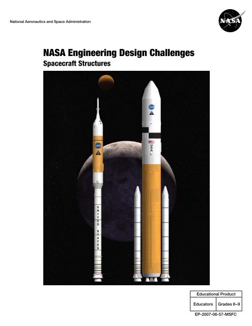
Cover Illustration:<strong>NASA</strong> Ares I and Ares V Launch Vehicles<strong>NASA</strong> artist conceptions.
<strong>NASA</strong> Engineering Design Challenge: <strong>Spacecraft</strong> <strong>Structures</strong> 2007 – iTable of Contents1. Overview.....................................................................................................12. How to Use This Guide..............................................................................33. National Science Education Standards...................................................44. Math Connections......................................................................................65. Thinking Skills...........................................................................................76. BackgroundThe Ares Launch Vehicles............................................................................ 8<strong>Spacecraft</strong> <strong>Structures</strong>.................................................................................. 97. Teacher PreparationRequired Materials......................................................................................13Build the Launcher.................................................................................... 15Build the Rockets...................................................................................... 17Practice Launching a Rocket.................................................................... 17Prepare the Materials for the Classroom.................................................. 18Teaching Strategies for an Engineering Design Challenge....................... 19Helping Students Understand the Design Process................................... 218. Classroom SessionsSession 1: Introducing the Challenge and Getting Started....................... 22Session 2: Design 1.................................................................................. 27Session 3 and 4: Designs 2, 3, 4, and 5.................................................... 31Session 5: Construct a Storyboard/Poster............................................... 34Session 6: Student Presentations............................................................. 36Linking Design Strategies and Observations to Science Concepts......... 379. Modifications and Extensions............................................................... 4410. Resources................................................................................................ 4611. Masters.................................................................................................... 49Flier for ParentsHandouts/TransparenciesRecording Sheets
ii – <strong>NASA</strong> Engineering Design Challenge: <strong>Spacecraft</strong> <strong>Structures</strong> 2007*The Ares Engineering Design Challenges use Traditional U.S. units of measureas the standard. Metric units follow in (parenthesis). In cases when a givenformula is traditionally calculated in metric units, for mathematical correctness,it is presented in that manner.NOTE: The Ares vehicles are a very preliminary configuration and will be subjectto change as the design progresses.AuthorsNick Haddad, T<strong>ER</strong>CHarold McWilliams, T<strong>ER</strong>CPaul Wagoner, T<strong>ER</strong>CSubject Matter Experts & ReviewersBob Bender: MSFC, <strong>Spacecraft</strong> & Vehicle Systems Department, QUALISJeff Finckenor: MSFC, <strong>Spacecraft</strong> & Vehicle Systems Department, <strong>NASA</strong>Kristy Hill: MSFC, Academic Affairs Office, WILL Technology Inc.Bill Pannell: MSFC, <strong>Spacecraft</strong> & Vehicle Systems Department, <strong>NASA</strong>Twila Schneider: MSFC, Ares Projects Office, Schafer CorporationDesign and LayoutSandra Schafer: Schafer LaCasse Design, Somerville, MAGraphicsTed Allbritton: MSFC, UNITeS Technical Publications & Illustrations, TRAXMelissa Higdon: MSFC, UNITeS Technical Publications & Illustrations, TRAXJennie Mitchell: MSFC, UNITeS Technical Publications & Illustrations, TRAXAres I and V<strong>NASA</strong> artist conceptionsEditorRegina Garson: MSFC, Ares Projects Office, UNITeS<strong>NASA</strong> explores for answers that power our future.www.nasa.gov
<strong>NASA</strong> Engineering Design Challenge: <strong>Spacecraft</strong> <strong>Structures</strong> 2007 – 1<strong>NASA</strong> Engineering DesignChallenges<strong>Spacecraft</strong> <strong>Structures</strong>1. OverviewSpace Transportation<strong>NASA</strong> Engineers at Marshall Space Flight Center, along with their partners atother <strong>NASA</strong> centers, and in private industry, are designing and beginning todevelop the next generation of spacecraft to transport cargo, equipment, andhuman explorers to space. These vehicles are part of the Constellation Program,which is carrying out a bold vision of human space exploration. The programincludes a crew exploration vehicle and the spacecraft to carry the crew to theMoon and later to Mars. The <strong>NASA</strong> Authorization Act of 2005 directs <strong>NASA</strong> toestablish a program to develop a sustained human presence on the Moon, whichwill serve as a stepping stone to further exploration of Mars and other destinations.This design challenge focuses on the Ares family of rockets, which willreplace the Space Shuttle in the task of putting people, satellites, and scientificexperiments into space.Figure 1.1. Thruststructure model.Connect to Engineering and ScienceThe Engineering Design Challenges connect students with the work of <strong>NASA</strong>engineers by engaging them in similar design challenges of their own. With somesimple and inexpensive materials, you, the teacher, can lead an exciting unit thatfocuses on a specific problem that <strong>NASA</strong> engineers must solve and the processthey use to solve it. In the classroom, students design, build, test, and revisetheir own solutions to problems that share fundamental science andengineering issues with the challenges facing <strong>NASA</strong> engineers.The Design ChallengeYou will present students with a challenge: Build a model thrust structure (theportion of the structure that attaches the engine to the rest of the spacecraft)that is as light as possible, yet, strong enough to withstand the load of a “launchto orbit” three times. See Figure 1.1. Students first determine the amount offorce needed to launch a model rocket to 3.3 feet (1 meter), which representslow Earth orbit. Then they design, build, and test their own structure designs.They revise their designs over several design sessions, trying to maintain orincrease the strength and reduce the weight of their structure. They documenttheir designs with sketches and written descriptions. As a culmination, studentscompile their results into a poster and present them to the class.Figure 1.2. Example launchtesting station.
2 – <strong>NASA</strong> Engineering Design Challenge: <strong>Spacecraft</strong> <strong>Structures</strong> 2007MaterialsYou will need a few simple and inexpensive materials:• Craft sticks.• Dowels.• Glue guns and hot-melt glue.• Corrugated cardboard.• 35 mm film canisters.• 1-liter soda bottles.• 2-liter soda bottles.• 25-50 pounds (11-23 kilograms) of sand.• A sturdy cloth bag to hold the sand.• Brass tubing.• Package sealing tape about 2 inches wide.• 4-ounce paper cups.Time RequiredThe design challenge can be carried out in six 45-minute class periods, but youcould easily extend it for twice that length of time. We provide some ideas forextensions at the end of the guide.You will need to invest 4-8 hours gathering the materials, building the test stand,trying out your own designs, reading the guide, and preparing the classroom.Value to StudentsThese activities help students achieve national goals in science, math, and thinkingskills. In the pilot testing of the design challenge, students embraced thedesign challenge with excitement. This activity will provide your students theopportunity to solve a challenge based on a real-world problem that is part ofthe space program and to use creativity, cleverness, and scientific knowledgein doing so. During these activities, students will have many opportunities tolearn about forces, structures, and energy transfer. The culminating activity givesstudents an opportunity to develop their presentation and communication skills.Student Research OpportunitiesThe "Resources" section of this guide includes many web sites where studentscan obtain additional information.Parent InvolvementThe "Masters" section of this guide includes a reproducible flier to send home toinform parents about the activity. It includes suggested activities students andparents can do at home together.SafetyThese activities meet accepted standards for laboratory science safety.
<strong>NASA</strong> Engineering Design Challenge: <strong>Spacecraft</strong> <strong>Structures</strong> 2007 – 32. How to Use This guideThis guide is divided into several sections:• National Science Education Standards.• Math Connections.• Thinking Skills.• Background Material.• Preparation for the Challenge.• Day-by-day Procedures.• Extensions.• Resources.• Masters.National StandardsIf you have questions about how this activity supports the National ScienceEducation Standards, Math Connections, or Thinking Skills, read those sectionsfirst. Otherwise, refer to those sections only as you need them.Suggested Order of ReadingFirst, skim through the entire guide to see what is included.Next, read through the “Classroom Sessions.” Give special attention to the lastpart, “Linking Design Strategies and Observations to Science Concepts,” onPage 37. This gives explicit suggestions on how to help students understandthe science in their designs. Review this section again after you start classroomwork with your students.Be sure to read the last two sections in the “Teacher Preparation” section:“Teaching Strategies for an Engineering Design Challenge,” on Page 19, and“Helping Students Understand the Design Process,” on Page 21. These will helpyou understand what is distinctive about an Engineering Design Challenge andhow your students can get the most out of it.When you understand the session-by-session flow and the pedagogicalapproach on which it is based, read the “Background” section. This will provideyou with information you will want to have in mind to “set the stage” for studentsand to link their classroom work with the work of <strong>NASA</strong> engineers. It focuses onone of the challenges faced by <strong>NASA</strong> engineers in developing a reusable launchvehicle: <strong>Spacecraft</strong> <strong>Structures</strong>.Further resources for you and your students can be found in the “Resources”section on Page 46.The reproducible masters you need are in the “Masters” section at the end ofthe book.Finally, read the remainder of “Teacher Preparation” to find out how to prepareyour classroom and yourself to conduct the Engineering Design Challenge.It contains safety guidelines, lists of materials, suggestions for organizing theclassroom, and teaching techniques.
4 – <strong>NASA</strong> Engineering Design Challenge: <strong>Spacecraft</strong> <strong>Structures</strong> 20073. National Science EducationStandardsThis Engineering Design Challenge supports the following Content Standardsfrom the National Research Council’s National Science Education Standards.Science as InquiryAll students should develop abilities necessary to do scientific inquiry.Students respond positively to thepractical, outcome orientation ofdesign problems before they areable to engage in the abstract,theoretical nature of many scientificinquiries.–National Science EducationStandards, National Research CouncilComplete text of the NationalScience Education Standardshttp://books.nap.edu/openbook.php?isbn=0309053269Complete text of Benchmarksfor Science Literacyhttp://www.project2061.org/publications/bsl/online/bolintro.htmFundamental Abilities and Concepts• Students should develop general abilities, such as systematic observation,making accurate measurements, and identifying and controlling variables.• Students should use appropriate tools and techniques, includingmathematics, to gather, analyze, and interpret data.• Students should base their explanation on what they observed, providingcauses for effects and establishing relationships based on evidence.• Students should think critically about evidence, deciding what evidenceshould be used, and accounting for anomalous data.• Students should begin to state some explanations in terms of the relationshipbetween two or more variables.• Students should develop the ability to listen to and respect the explanationsproposed by other students.• Students should become competent at communicating experimentalmethods, following instructions, describing observations, summarizingthe results of other groups, and telling other students about investigationsand explanations.• Students should use mathematics in all aspects of scientific inquiry.• Mathematics is important in all aspects of scientific inquiry.• Technology used to gather data enhances accuracy and allows scientiststo analyze and quantify results of investigations.• Scientific explanations emphasize evidence.• Scientific investigations sometimes generate new procedures for investigationor develop new technologies to improve the collection of data.Physical ScienceAll students should develop an understanding of motions and forces.Fundamental Concepts and Principles, Grades 5-8• An object that is not being subjected to a force will continue to move at aconstant speed and in a straight line.• If more than one force acts on an object along a straight line, then theforces will reinforce or cancel one another, depending on their directionand magnitude. Unbalanced forces will cause changes in the speed ordirection of an object’s motion.• Energy is transferred in many ways.
<strong>NASA</strong> Engineering Design Challenge: <strong>Spacecraft</strong> <strong>Structures</strong> 2007 – 5Fundamental Concepts and Principles, Grades 9-12• Objects change their motion only when a net force is applied. Laws ofmotion are used to precisely calculate the effects of forces on the motionof objects. The magnitude of the change in motion can be calculated usingthe relationship F=ma, which is independent of the nature of the force.Whenever one object exerts a force on another, a force equal in magnitudeand opposite in direction is exerted on the first object.Science and TechnologyAll students should develop abilities of technological design.Fundamental Concepts and Principles1. Design a solution or product.• Consider constraints.• Communicate ideas with drawings and simple models.2. Implement a design.• Organize materials.• Plan work.• Work as collaborative group.• Use suitable tools and techniques.• Use appropriate measurement methods.3. Evaluate the design.• Consider factors affecting acceptability and suitability.• Develop measures of quality.• Suggest improvements.• Try modifications.• Communicate the process of design.• Identify stages of problem identification, solution design, implementation,evaluation.The challenge satisfies the following criteria for suitable design tasks:Through design and technologyprojects, students can engage inproblem-solving related to a widerange of real-world contexts. Byundertaking design projects, studentscan encounter technologyissues even though they cannotdefine technology. They shouldhave their attention called to theuse of tools and instruments inscience and the use of practicalknowledge to solve problemsbefore the underlying concepts areunderstood.–Benchmarks forScience Literacy, AAAS• Well defined, not confusing.• Based on contexts immediately familiar to students.• Has only a few well-defined ways to solve the problem.• Involves only one or two scientific concepts.• Involves construction that can be readily accomplished by students,not involve lengthy learning of new physical skills, and not require timeconsumingpreparation or assembly.All students should develop understandings about science and technology.• Difference between scientific inquiry and technological design.• Technological designs have constraints.• Technologies cost, carry risks, and provide benefits.• Perfectly designed solutions do not exist; engineers build in back-upsystems.
6 – <strong>NASA</strong> Engineering Design Challenge: <strong>Spacecraft</strong> <strong>Structures</strong> 20074. Math ConnectionsThis Engineering Design Challenge offers the opportunity to integrate a variety ofmath skills*, described in the following table. Some of the listed applications arepart of extension activities.SkillPerforming operationswith decimal numbersRoundingCalculating averagesGraphingMeasuring percentage improvementCalculating ratiosUsing formulasUsing a budgetApplicationMass of structure, quantitiesof materialsRounding mass of structure to thegram, tenth of a gram, etc.Calculating average, mean, median,mode, or range for all designs by oneteam, or for the entire classCreating line graphs, bar graphs, circlegraphs, or scatterplot of structuremass versus launch successGraphing number of successfullaunches vs. mass of the structureGraphing number of successfullaunches vs. size (width, length, diameter)of the structureComparing designs by one team,calculating improvement for the entireclassDetermining the relationship betweenthe quantity of materials used andthe number of successful launches;between the mass dropped and thelaunch heightCalculating gravitational potentialenergy, PE = mgh and kinetic energy,KE = 1/2 mv 2See the extension activity: Limitingdesigns by cost*The Ares Engineering Design Challenges use Traditional U.S. units of measureas the standard. Metric units follow in (parenthesis). In cases when a givenformula is traditionally calculated in metric units, for mathematical correctness,it is presented in that manner.
<strong>NASA</strong> Engineering Design Challenge: <strong>Spacecraft</strong> <strong>Structures</strong> 2007 – 75. Thinking SkillsThis Engineering Design Challenge provides an opportunity to assess students’development of critical thinking skills in a context in which these skills areapplied throughout the task. Students are often asked to perform critical thinkingtasks only after they have mastered such lower-level thinking skills as makingsimple inferences, organizing, and ranking. In this learning activity, various levelsof thinking skills are integrated. The following rubric is designed to assist you inassessing student mastery of thinking skills.Cognitive Memory Skills1. Students accurately measure the drop height and compute the averageheight.2. Students observe a design before testing and pick out the “key features.”3. Students observe a model during and after testing and document preciselywhat happens to the model.4. Students record observations and organize data so that they can beexchanged with others and referred to later.Structuring, Organizing, Relating Skills5. Students can classify designs.6. Students can rank designs according to various criteria, i.e., strength, mass.7. Students can create diagrams, charts and graphs of the results.8. Students can visualize relationships such as part-whole, cause-effect.9. Students can interpret such information as test results and designdocumentation.10. Students can compare and contrast different design solutions.Convergent and Generalizing Skills11. Students can demonstrate that they understand the challenge.12. Students can draw conclusions and generalize.13. Students can converge on a solution by choosing from alternatives.Divergent Thinking Skills14. Students can apply ideas and concepts of motions and forces to theirdesigns.15. Students can make inferences and predictions about the performanceof a design.16. Students can invent and synthesize a solution.17. Students can devise an experiment to test a particular theory.18. Students can balance trade-offs between cost, quality, safety, efficiency,appearance, and time.Evaluation Skills19. Students can evaluate designs based on given criteria.20. Students value new knowledge.
8 – <strong>NASA</strong> Engineering Design Challenge: <strong>Spacecraft</strong> <strong>Structures</strong> 20076. BackgroundThe Ares Launch VehiclesOn July 20, 1969, Neil Armstrong and Buzz Aldrin became the first humans to set footon the Moon. They arrived there in a lunar lander, which had been propelled into orbitaround the Moon as part of the Apollo 11 space flight. <strong>NASA</strong> now has plans to returnhumans to the Moon and eventually to Mars. <strong>NASA</strong> is designing new spacecraft tocarry them there. These spacecraft are known as the Ares launch vehicles.<strong>NASA</strong> Engineers at Marshall Space Flight Center are currently developing the launchvehicles for the next generation of space travel. The Ares I crew launch vehicle willdeliver the Orion crew exploration vehicle into Earth orbit. Astronauts in Orion can thendock with the International Space Station, or rendezvous with the Altair lunar lander,put into orbit by the Ares V launch vehicle for transport to the Moon.Ares I is a two-stage rocket. (See Figure 6.1.) The first stage is a reusable solid rocketbooster (RSRB) similar to the boosters of the Space Shuttle. Its second stage is a liquidoxygen-liquid hydrogen engine similar to the upper stage engine of the Saturn V rocket,which propelled the Apollo missions to the Moon. Ares I will weigh 2 million pounds(907 metric tons) at liftoff, will stand about 325 feet tall (100 meters), more than a footballfield, and will deliver the Orion crew exploration vehicle to low Earth orbit (LEO).Ares I will produce roughly 3.5 million pounds-force (15.6 meganewtons) of thrust atliftoff. The RSRB booster will burn for about 126 seconds. At the end of this burn, therocket will be about 36 miles (58 kilometers) above Earth, traveling at a speed of 4,445miles per hour (2,000 m/sec). The vehicle will have lost 69% of its weight by havingburned up 1.4 million pounds (630 metric tons) of solid rocket fuel. The RSRB, nolonger needed, will be jettisoned and will fall back to Earth, where it will be recoveredto be used again. The liquid fuel J-2X engine of the Ares I upper stage will burn forabout 464 seconds, producing 294,000 pounds (1.3 meganewtons) of thrust, to liftthe crew module to a higher orbit at 185 miles (298 kilometers) above the Earth. In thisorbit, the vehicle will be traveling at about 17,500 miles per hour (7,800 m/sec).Ares V, shown in Figure 6.2, is <strong>NASA</strong>’s heavy-lift cargo vehicle that will enable <strong>NASA</strong>to send more crew and more cargo to the Moon than the Apollo-era Saturn V. AresV will weigh 7.4 million pounds (3,357 metric tons) at liftoff, will stand 360 feet (110meters) tall, and can carry 287,000 pounds (130 metric tons) to LEO. The Saturn Vwas 4 feet (1.2 meters) taller but weighed nearly 1 million pounds (453,600 kilograms)less than Ares V and carried approximately 39,000 pounds (17,690 kilograms) lessto the Moon. Ares V has a payload shroud more than 32 feet (10 meters) in diameterfor carrying more massive payloads. It is this unmatched lift capability that will notonly support extended exploration of most of the lunar surface, but will also supportnumerous human and robotic missions of exploration beyond the Moon.Figure 6.1.Ares I.Figure 6.2.Ares V.Ares V has two stages. The first stage is powered by two solid rocket boosters similarto the Ares I first stage and a core stage powered by five commercial RS-68 liquid fuelengines working together. After the boosters burn out, they fall to Earth, and the corestage continues operating to an altitude of roughly 87 miles (140 kilometers). The stagefalls to Earth, and the second stage, called the Earth departure stage (EDS), ignitesto place the lunar lander, Altair, in Earth orbit. The EDS is powered by the same J-2Xengine as the Ares I upper stage. After the astronauts in Orion rendezvous and dockwith Altair, the EDS ignites again to send the Orion, Altair, and the crew to the Moon.
<strong>NASA</strong> Engineering Design Challenge: <strong>Spacecraft</strong> <strong>Structures</strong> 2007 – 9<strong>Spacecraft</strong> <strong>Structures</strong>Every pound that is carried to space requires fuel to do so, regardless of whetherthat pound is cargo, crew, fuel, or part of the spacecraft itself. The more thevehicle and fuel weigh, the fewer passengers and smaller payload the vehiclecan carry. Designers try to keep all the parts of the vehicle, including the skeleton(or structure), as light as possible. To design a lightweight structure is verydifficult, because it must be strong enough to withstand the tremendous thrust(or force) of the engines during liftoff. Throughout the history of space vehicles,engineers have used various strategies for the structure.In order to make the Ares spacecraft as light as possible, <strong>NASA</strong> engineersare constructing them of lightweight, strong materials, such as Al-Li 2195, analuminum-lithium alloy, which is less dense and stiffer than pure aluminum.<strong>NASA</strong> engineers also design structures that use as little material as possible toachieve the strength and rigidity they need. So, for example, they make use of anetwork of hollow tubular struts (called a truss) rather than use more compact,but heavier solid beams.This engineering design challenge focuses on the Ares V thrust structure, whichattaches the five liquid fuel engines of the Ares V to the body of the spacecraft.The thrust structure is an essential part of the spacecraft, which must be keptlightweight. As they burn, the five RS-68 engines of the Ares V produce about3,510,275 pounds (1,592 metric tons) of thrust. This means that the thrust structuremust bear a load equivalent to 3,510,275 pounds (1,592 metric tons) ofweight pushing on it. The thrust structure must not only withstand this terrificforce, it must transfer it to the vehicle in a balanced way, without damaging thevehicle.Students can calculate the “payload”to total weight ratios for (a)the family car and (b) a studentriding a bicycle.Students may be familiar withdesign strategies used to makelightweight bicycles.Figure 6.3. View of Ares V engines and thrust structure. Thisimage appears in a larger version in the "Masters" section.Figure 6.4. Ares V engines attached tothrust structure. This image appears ina larger version in the ”Masters” section.
10 – <strong>NASA</strong> Engineering Design Challenge: <strong>Spacecraft</strong> <strong>Structures</strong> 2007Figure 6.5.Ares I.Ares ILength: 325 feet (100 meters)Width: 18 feet (5.5 meters)Takeoff weight: 2 million pounds(907 metric tons)Propellant fuel weight: 1.7 millionpounds (764 metric tons)Main propulsion: single RSRBTake-off thrust: 3.5 million poundsforce(15.6 meganewtons)Maximum speed: 17,500 miles/hr(7,800 m/sec)Maximum speeds at end of staging:Ares I First Stage: 6250 ft/sec(1,904 m/sec)Ares I Upper Stage Orbit Injection:25,582 ft/sec (7,798 m/sec)Largest payload it can carry into orbit:56,512 pounds (25.6 metric tons)Figure 6.7. Space Shuttle.Space ShuttleLength Orbiter: 122 feet(37 meters),Overall: 184 feet (56 meters).Width Orbiter: 56.67 feet (17.3 meters),Overall: 76.6 feet (23 meters)Takeoff weight: 4.5 million pounds(2,041 metric tons)Fuel weight: 4.3 million pounds,including Solid Rocket Boosters andexternal fuel tank (1,937 metric tons)Main propulsion: 3 Main Engines,2 Solid Rocket BoostersTake-off thrust: 3.3 million pounds or(1,497 metric tons)Maximum speed:17,500 miles/hr (7,800 m/sec)Figure 6.6.Ares V.Largest payload it can carry into orbit:50,000 pounds (22.7 metric tons)Ares VLength: 360 feet (110 meters)Core stage diameter: 33 feet (10 meters)Takeoff weight: 7.4 million pounds(3,357 metric tons)Core stage fuel weight: 3.16 million lbs(1,435.5 metric tons)Main propulsion: 2 RSRBs plus5 RS-68 liquid fuel enginesTake-off thrust: 10.65 million pounds(47.4 meganewtons)Maximum speed: 24,462 mi/hr(10,935 m/sec)*Maximum speeds at end of staging:Ares V SRB separation: 3,958 ft/sec(1,206 m/sec)Ares V Core stage cutoff: 16,227 ft/sec(14,946 m/sec)Ares V Earth Departure Stage (orbitalburn): 25,460 ft/sec (7,760 m/sec)Largest payload it can carry into orbit:287,000 pounds (130 metric tons)*Trans-Lunar Injection (TLI)NOTE: The Ares vehicles are a verypreliminary configuration and willbe subject to change as the designprogresses.
<strong>NASA</strong> Engineering Design Challenge: <strong>Spacecraft</strong> <strong>Structures</strong> 2007 – 11Questions for class discussion or homework1. Why is it important to make the launch vehicle as lightweight as possible?________________________________________________________________________________________________________________________________________________2. What are the Ares launch vehicles?________________________________________________________________________________________________________________________________________________3. What are some ways <strong>NASA</strong> engineers could make the Ares launch vehicles aslightweight as possible?________________________________________________________________________________________________________________________________________________________________________________________________________________________________________________________________________________________________________________________________________________________________________4. If it costs $10,000 to lift a pound (half a kilogram) of payload into orbit aboardthe International Space Station, calculate the cost of sending yourself intospace. How much would it cost to send yourself, your family and your petsinto space?________________________________________________________________________________________________________________________________________________________________________________________________________________________________________________________________________________________________________________________________________________________________________________________________________________________________________________________________________________________________________________________________________________________________________________________________
12 – <strong>NASA</strong> Engineering Design Challenge: <strong>Spacecraft</strong> <strong>Structures</strong> 2007Answers to questions for class discussion or homework1. To maximize the amount of payload it can carry to orbit.2. The Ares I and V are the next generation of space launch vehicles.3. By making the vehicles of a lightweight composite material and by using atruss structure to support the engines.4. Answers will vary.
<strong>NASA</strong> Engineering Design Challenge: <strong>Spacecraft</strong> <strong>Structures</strong> 2007 – 137. Teacher PreparationIn order to prepare yourself and your classroom for this Engineering DesignChallenge, you should:• Use the Background Information section in this guide, and the EngineeringDesign Challenge web site at http://edc.nasa.gov to familiarize yourselfboth with the spacecraft structures used by <strong>NASA</strong> and the science andengineering concepts you will be introducing.• Read through the day-by-day activities in the following section of thisguide.• Gather the required materials.• Build the launcher.• Build the test rockets.• Practice the test procedure with your own designs.• Prepare the materials for the classroom.• Set up the classroom.• Organize students in teams.• Review safety procedures.• Notify parents using the flier included in the “Masters” section.Required MaterialsRequired MaterialsApproximate costper unitMinimum quantityfor a few teams(60 structures)Recommended quantityfor 12–15 teams(120 structures)Add for eachadditional team(10 structures)Craft Sticks 1/2¢ 1500 3000 250Dowels 15 to 50¢ for 3 ft. 5 5 0Hot-melt Glue(low-temperature type)5 to 50¢ per stick 12 20 2Corrugated Cardboard free 60 120 1035 mm Film Cans free 10 20 11-liter Soda Bottles free or 5¢ 8 20 12-liter Soda Bottles free or 5¢ 3 5 0Weight$2.35 for a 50-lb(23-kg) bag of sand20 to 50 lbs totalBrass Launch Tubes 80¢ for 4 inches 4 8 1Package Tape $2.00 1 roll 1 roll 0Small Paper Cups 4-oz, waxed 2 or 3¢ 12 36 3
<strong>NASA</strong> Engineering Design Challenge: <strong>Spacecraft</strong> <strong>Structures</strong> 2007 – 15Build the LauncherMaterials NeededRing Stand (Launch Rod)A ring stand of the type used in chemistry labs with a vertical rod 1/2 inch indiameter and approximately 3 feet (1 meter) tall. (This is taller than most.) Thekind with a large heavy base is best.You can use any straight metal rod 1/2 inch in diameter and 3 to 4 feet (0.9 to 1.2meters) long if it can be attached to a suitable base. If you have a way to threadsuch a rod for several inches at one end, you can then attach it to a base withnuts and washers.Weight for DroppingA sturdy cloth bag about the size of a loaf of bread containing about 15 to 20pounds (7 to 9 kilograms) of sand or fine gravel will work well. If you plan to docalculations using the mass of the dropped weight, 22 pounds (10 kilograms)provides a convenient figure. Lead shot makes an excellent filler for the dropweight. Sturdy sewing of the bag is important.Wooden 2 by 31 piece 50 inches (1.3 meters) long (for the launch lever)1 piece 4 inches (10 centimeters) long (for the mounting block)You can use a 2 by 4 in place of the 2 by 3. This works just fine. The 2 by 4 isheavier than necessary.Plywood Base Board3/4 or 1/2 inch thick, 10 by 14 inches (25.4 by 35.6 centimeters). Any size from8 by 12 inches (20 by 30.5 centimeters) to 12 by 16 inches (30.5 by 40.6 centimeters)is fine.HingeA “T” style hinge is ideal. A good size has one flap 3 1/2 inches (9 centimeters)wide (in the direction of the pivot pin) and about 1 inch (2.54 centimeters) long.The other flap is triangular, about 1 1/2 inches (3.8 centimeters) wide at the pin,and about 4 inches (10 centimeters) long. This kind of hinge costs about $3.00.You may use almost any kind of sturdy hinge that can be attached to the launchlever and the mounting block.Figure 7.1. Example launchtesting station.Flat Head Wood ScrewsThese attach the hinge to both 2 by 3s and the 2 by 3 to the base board.Anything that fits will work fine. The hinge needs screws that match the hingeand the mounting block should be mounted with screws long enough to gosolidly into the block. See Figure 7.1.
16 – <strong>NASA</strong> Engineering Design Challenge: <strong>Spacecraft</strong> <strong>Structures</strong> 2007ConstructionIt will be easiest to assemble the launcher if you begin by locating the placeswhere screws will go and drill pilot holes for all of them before you screwtogether any of the parts.Midpoint of LeverFigure 7.2. Side view of base,hinge, block, and lever.1. Place the hinge on the launch lever (2 by 3 wood length) so that the pivot pinof the hinge is at the midpoint of the length of the launch lever. Mark the locationfor the screws. See Figure 7.2. (If you want to be able to move the hingeto a different location as explained in “Alternate Hinge Location” below, this isthe best time to mark the additional mounting holes.)2. Put the mounting block next to the short flap of the hinge. Mount the hinge ata height so that the launch lever will be able to swing in both directions about2 to 3 inches (5 to 8 centimeters) from horizontal. If you mount the hinge toolow, the lever will be able to swing in only one direction; its motion in the otherdirection will be blocked by the mounting block. Mark the location for thosescrews on the mounting block.3. Place the mounting block in the center of the base board and mark on thebottom of the base board the location for the screws to attach the mountingblock to the baseboard.4. Drill pilot holes through the base board into the mounting block.5. Drill pilot holes for the hinge mounting screws in the mounting block andlaunch lever.6. Drill clearance holes for the wood screws in the baseboard and countersinkthem. The heads of the screws need to sink into a prepared depression sothey are flush with or below the baseboard surface.7. Screw the short flap of the hinge to the mounting block, screw the long flapof the hinge to the launch lever, and screw the mounting block to the baseboard. See Figure 7.3. (This is the order of assembly that provides easiestaccess for the screwdriver.)Optional ImprovementsAlternate Hinge LocationYou might want to experiment with moving the hinge point to a position 20inches (0.5 meter) from one end, so that the ratio of the lengths of the ends ofthe lever is 2 to 3.Figure 7.3. End view of base,block, hinge, and lever.One Piece Launch StandIf you mount the launch rod and the launch lever on the same base board theywill stay correctly aligned.
<strong>NASA</strong> Engineering Design Challenge: <strong>Spacecraft</strong> <strong>Structures</strong> 2007 – 17Build the RocketsMaterials NeededSoda Bottles (and Caps)You will use the 1-liter size for most of the rockets, but it is good to have some2-liter bottles on hand as well. The bottles that have a 5-lobe base are better forthis activity than other kinds. See Figure 7.4.Brass Launch TubesCraft, art supply, and hobby stores sell brass tubing in sizes that just fit insideeach other, so it is sometimes called “telescoping tubing.” It comes in 12-inchlengths. 9/16 inch outside diameter is just right to fit easily over the launch rod(the ring stand). You will need to cut the tube into 4-inch (10-centimeter) lengths,which you can do with a tubing cutter or a fine saw. You can also use PVC pipewith a similar diameter.Figure 7.4. Bottle with a 5-lobe base.Package TapeThis is used to attach the launch tube to the soda bottle. See Figure 7.5.ConstructionFill the bottle with water and cap it tightly. Tape a 4-inch (10-centimeter) length oftube to the flat cylindrical part of the bottle. Be sure the tube is vertical.Practice Launching a RocketOnce you have constructed the launcher and rockets, you will want to try somemodels yourself to become familiar with adjusting the launcher and assuringconsistent test conditions.You will need at least one other person, or two if you want to observe the launchprocedure rather than doing it yourself. One person will drop the weight on theend of the lever. The other person will catch the bottle after it reaches its peakand begins descending.Figure 7.5. Brass tube attachedto bottle with package tape.Slide the rocket tube onto the ring stand and centerthe bottle on the end of the launch lever. See Figure7.6. The end of the lever should be as close to thering stand as it can get without hitting it as it pivots.The “catcher” should stand behind or to the side ofthe launch rod and signal when ready for the launch.At this signal, the “dropper” should count down anddrop the weight from about knee-high squarely onthe other end of the lever. See Figure 7.7.Figure 7.6. Forces before launch.
18 – <strong>NASA</strong> Engineering Design Challenge: <strong>Spacecraft</strong> <strong>Structures</strong> 2007Notice that the lever and the launch rod may move slightly out of alignmentduring each launch. You will want to make sure that the lever is square with thelaunch rod and that the bottle (and the thrust structure when there is one underthe bottle) is centered on the lever before each launch.Figure 7.7. Testing a thruststructure.Prepare the Materials for the ClassroomYou may wish to assemble the materials into kits before distributing them tostudents. In this way you can reduce the amount of time spent on distributingmaterials. You can also ensure that all design teams receive the same materials.If you choose to incorporate the additional design constraint of a budget(described in the “Extensions” section on Page 44 of this guide), assembling kitsin advance will simplify tracking the budget.Set up the ClassroomTeam Work AreaSet up the classroom for laboratory work to be done in teams. Each pair ofstudents should have a clear work area near an electrical outlet (for the glue gun)where they can organize their materials and build their designs. A classroomdesk or table will do.LauncherSet up the launcher, in a central location away from walls, where students cangather around.
20 – <strong>NASA</strong> Engineering Design Challenge: <strong>Spacecraft</strong> <strong>Structures</strong> 2007• Steer students toward a more scientific approach. If they have changedmultiple aspects of a design and observed changes in results, askstudents which of the things they changed caused the difference inperformance. If they are not sure what caused the change, suggest theytry changing only one or two of the aspects. This helps them learn thevalue of controlling variables.• Be aware of differences in approach between students. For example, somestudents will want to work longer on a single design to get it “just right.”Make it clear that getting the structure designed, tested, and documentedon time is part of the challenge. If they do not test a lot of models, they willnot have a story to tell at the end. Remind them that engineers must comeup with solutions in a reasonable amount of time.• Model brainstorming, careful observation, and detailed description usingappropriate vocabulary.• Ask open-ended “guiding” or “focusing” questions. For example: “Howdoes the force get from the launch lever to the rocket?” or “What madethis design stronger than another?” Keep coming back to these questionsas the students try different designs. Encourage students to address thesequestions in their journals.• Require students to use specific language and be precise about what theyare describing. Encourage them to refer to a specific element of the design(column, strut, joint, brace, etc.) rather than “it.”• Compare designs to those of other groups. Endorse borrowing. Afterall, engineers borrow a good idea whenever they can. However, be surethat the team that came up with the good ideas is given credit in documentationand in the pre-test presentation. Borrowing should also bedocumented in student journals.• Emphasize improvement over competition. The goal of the challenge isfor each team to improve its own design. However, there should be somerecognition for designs that perform extremely well. There should alsobe recognition for teams whose designs improve the most, for teamsthat originate design innovations that are used by others, for elegance ofdesign, and for quality construction.• Classify designs and encourage the students to come up with their ownnames for the designs to be used in the class.• Encourage conjecturing. Get students to articulate what they are doing inthe form of, “I want to see what will happen if…”• Connect what students are doing to what engineers do. It will helpstudents see the significance of the design challenge if they can see thatthe process they are following is the same process that adult engineersfollow.
<strong>NASA</strong> Engineering Design Challenge: <strong>Spacecraft</strong> <strong>Structures</strong> 2007 – 21Helping Students Understand theDesign ProcessEngineering involves systematically working to solve problems. To do this, engineersemploy an iterative process of design-test-redesign, until they reach asatisfactory solution. See Figure 7.8.In the Engineering Design Challenges, students experience this process. To helpstudents visualize the cyclic nature of the design process, we have provided areproducible chart that you can use in a class discussion.Once students have sufficient experience in designing, building, and testingmodels, it is valuable for them to formally describe the design process they areundertaking. Students require a significant amount of reinforcement to learn thatthey should study not just their own results, but the results of other teams aswell. They need to realize that they can learn from the successes and failures ofothers, too.Select a time when you feel the students have had enough experience with thedesign process to be able to discuss it. Use the black-line master of “The DesignProcess” to make an overhead transparency. Project it on a screen. Then, usingit as a guide, go through the process step-by-step, using a sample design as anillustration. It is useful to hold up the model and point out specific features thatmay be the result of studying the test data, unsuccessful builds, or additionalresearch. For example, using a particular model, ask “How did this feature comeabout? Where did you get the idea? Was it the result of a previous test, done byeither you or by another team?”The Design ProcessDesignAnalyzeResultsBuildRecord DataTestFigure 7.8. A larger version of this image is included in the “Masters” section at the endof this guide.
22 – <strong>NASA</strong> Engineering Design Challenge: <strong>Spacecraft</strong> <strong>Structures</strong> 20078. Classroom SessionsSession 1Introducing the Challenge and Getting StartedIn this first session, you will introduce the activity and provide students withbackground information about <strong>NASA</strong>, the Ares launch vehicles, and spacecraftstructures. You will define the challenge and discuss how engineers approacha design problem. Students will practice dropping the sandbag until they canconsistently launch the bottle rocket to orbit. You will conclude the session bylaunching a teacher-built model thrust structure and challenging students tobuild models that are lighter-weight.Learning Goals• Understand and define thrust structure.• Recognize the need for models.• Understand the relationship between a model and the actual objectbeing designed.• Recognize a need for a standard test procedure.• Make observations and collect data.• Understand the need for averaging.• Calculate averages.Materials• Transparencies for overhead projector. (Masters can be found at the end ofthis guide.)– Ares Launch Vehicles.– Thrust <strong>Structures</strong>.– The Challenge.• Launch stand (includes launch lever, ring stand, weight to drop, bottlerocket and yard stick or ring stand with file card to set drop height).• A too-heavy overbuilt thrust structure built by the teacher. (See section6 later in this session for a model.)• Yard stick (or meter stick).• File card or similar size piece of a manila folder.• Wall chart (or chalkboard) for recording drop heights and launch results.Optional:• Additional ring stand.• Third ring stand.• String.
<strong>NASA</strong> Engineering Design Challenge: <strong>Spacecraft</strong> <strong>Structures</strong> 2007 – 231. Introduce the UnitElicit students’ knowledge of the Space Shuttle, the International Space Station,the Apollo missions to the Moon, and spacecraft in general. Use the backgroundinformation in the previous section, and pictures, video, or models of the Aresvehicles to introduce the concept of a reusable launch vehicle. Introduce theAres launch vehicles, which are being designed to replace the Space Shuttle.Ask about what needs to be considered in designing a vehicle that must getinto space and return to Earth. Discuss the significance of mass (optional:discuss the difference between weight and mass). Explain to students that theywill take on the role of engineers for this unit. They will attempt to solve a problemthat <strong>NASA</strong> engineers are working on designing: A lightweight, but strongthrust structure for the vehicle.2. Introduce the ChallengeBring out the launch stand and choose a student to be the catcher. Launch arocket; but, drop the weight so that the rocket barely moves. Ask students toidentify which parts of the rocket each part of the model represents. (The leveris the “engine” providing the thrust, the sandbag weight represents the energyof the engines, and the bottle is the body of the spacecraft including the liquidfuel tanks.)Explain to students that the thrust structure is the part of the spacecraft’s skeletonthat holds the engine on to the rest of the vehicle. Use the “Thrust Structure”masters to compare the Ares rocket thrust structure to the bottle rocket thruststructure. Explain that, unlike the demonstration in which the bottle “rocket” getsone big push from the lever “engine” and then separates from it, a launch vehiclemust be pushed constantly by the engine until it reaches orbit. The Ares I and Vmust carry their engines with them. The push of the engine must travel throughthe thrust structure to the rest of the rocket.Define the challenge. Either use a transparency made from the “Design Challenges”master at the end of this guide, post a copy prominently in the room,or hand out copies to each team of students.Figure 8.1. Ares I and Ares V.
24 – <strong>NASA</strong> Engineering Design Challenge: <strong>Spacecraft</strong> <strong>Structures</strong> 2007The challenge:Build the lightest weight thrust structure that will withstand the force of launch to orbit at least three times.Launch to orbit = propelling a 1-liter bottle of water to the height of approximately 3 feet (1 meter) into the air.Design constraints:Use only the specified materials.The thrust structure must be taller than 2 inches (5 centimeters) and must allow space in the center for fuellines and valves represented by a 35mm-film canister without its lid.Explain to students that during the following three class sessions, they willdesign a thrust structure, launch it, record the results, and then try to improve onthe design by making it lighter and stronger. They will get at least four chances toimprove on the design. Show students your heavy design, and tell them that youare sure they can do better!3. Explain the “Culminating Activity”Explain that each team will spend one class period at the end of the challengeconstructing a “storyboard” or poster that will tell the story of the developmentof their thrust structure. Using the storyboard, each team will then make apresentation to the class explaining the evolution of their design.The storyboard should contain at least three of the team’s recording sheets. Ifpossible, students should attach three of the actual tested models. The postershould show the evolution of the team’s design from its initial to intermediate andfinal design stages. Essentially, it should “tell the story” of the design processand explain how and why the design changed. It should conclude with a concisestatement of “what we learned.”In addition to completing the recording sheets, direct students to keep runningnotes, diagrams, questions, research findings, data, etc., in a journal or log. Thesejournals will provide an excellent resource for documenting their experience whenthey need to make their storyboard.4. Determine the “Engine Thrust”Explain to students that their first task will be to determine the necessary thrustto propel the bottle rocket “to orbit.” They will determine a drop height for thesandbag so that the rocket just flies off the ring stand. Discuss with studentswhy you do not want it to fly too far off the launch rod. (That would be subjectingthe structure to more force than necessary and overshooting “orbit.”)Choose a volunteer to drop the sandbag and another to catch the rocket.(Launch this rocket without a thrust structure.) Measure the height of the dropwith a yard stick or measuring tape or punch a small hole in a file card or pieceof manila folder and slide it on a ring stand to mark the height. Have the studentsstart by dropping the weight from a very low height and gradually increase thedrop height until the bottle just barely flies off the ring stand. You might have adifferent pair of students perform the launch with each increase in drop height.
<strong>NASA</strong> Engineering Design Challenge: <strong>Spacecraft</strong> <strong>Structures</strong> 2007 – 25Continue to launch the rocket until students can consistently launch the bottlethree times to the desired height. You might want several pairs of students toconfirm the height.When you have determined the optimal drop height, record it and post it in thesame place as the challenge. Mark a ring stand at that height with tape or tapethe file card onto the ring stand. Optional: Use two ring stands and tie a stringbetween them at the drop height.Optional: Use Different Drop Mass and Drop HeightIf you are able to conveniently change the mass being dropped, you couldchoose a drop height and then find the required mass for launching the bottleto orbit using that weight. Students could record the results of using differentamounts of sand in a table such as this:Trial #123Launch Masspounds (kg)5. Discuss the ResultsDrop Masspounds (kg)Drop Heightinches (cm)Altitudeinches (cm)Orbit?(Y/N)Ask students: How much mass are we launching to orbit? (2.2 pounds or a 1kilogram bag of sand.) What’s the source of the propulsive force? (22 pounds ora 10 kilogram bag of sand.) What forces are acting on the bag of sand when it issuspended in the air before the drop? (Gravity and the student’s muscles.) Whatforces are acting on the bag when it is released? (Gravity.) Trace where the forcegoes. (Down on one side, up from the other end of the lever.) Optional: Discusswhy it is important for the lever to be stiff rather than flexible.It is instructive for students to think about how the model bottle rocket and anactual rocket, such as the Ares V, are the same and different. Here are typical“answers.”Bottle RocketAres VSource of the thrust The lever2 solid rocket boostersplus 5 liquid fuel enginesSource of engine energy Gravity on sandbag Combustion of fuel creates itThrust duration Fraction of a second MinutesThrust magnitude Small10.65 million pounds(47.4 meganewtons)Mass of rocket2.2 pounds (1 kilogram)7,400,000 pounds(3,356 metric tons)Thrust depends onMass of sandbagDrop heightStrength of gravityEnergy density of fuelMass of fuel burned/secEngine designIf you graph the data in this tableyou may see some interestingrelationships.Homework/Assessment. Sketchthe test stand and identify therelevant parts. If you wanted topropel your 1-liter bottle rocket toa height of 1 yard, how much massshould you drop on the end of thelever and from what height?Use the master, “Comparing theBottle Rocket and the Ares V,” asan overhead and discuss how the“model” compares with the “realthing.”
26 – <strong>NASA</strong> Engineering Design Challenge: <strong>Spacecraft</strong> <strong>Structures</strong> 20076. Demonstrate a Poorly Designed Baseline Model(Note: If time does not allow for this demonstration in this session, it can be leftuntil Session 2, Step 6.) In order to provide a baseline model for a thrust structure,you should build one that is truly a juggernaut. See Figure 8.2. For example,use 3-inch (7.6-centimeter) lengths of 1/4-inch dowels clustered in threes andattached to cardboard plates on top and bottom using a generous amount ofglue. This structure will have a mass little more than 4 ounces (113 grams) butwill certainly withstand numerous launches. Students will quickly see ways toimprove upon this crude design and will take pleasure in building a model that isbetter than the teacher’s.Figure 8.2. A heavy design.7. Wrap-upShow students the craft sticks and the square of cardboard they will use for theirfirst design. Ask them to think about thrust structure designs before the nextsession.
<strong>NASA</strong> Engineering Design Challenge: <strong>Spacecraft</strong> <strong>Structures</strong> 2007 – 27Session 2Design 1In this session, students design and build their first thrust structure using theprovided materials. It is important during this session to establish consistentprocedures for testing including:• Pre-test approval of design and recording sheet.• Oral presentation of key design features by students before launch.• Accurate testing and reporting of results on Test Results Sheet.• Post-test discussion of the design and the test results.Learning Goals• Practice construction techniques including use of glue pot or glue gun.• Recognize the need for clear documentation.• Practice documenting design.• Practice making and recording observations.• Begin thinking about how to make designs strong and lightweight.Materials• Launch stand, sand bag, ring stand.• Craft sticks.• Glue guns and glue sticks.• 3 1/2 by 3 1/2 inch square (9 by 9 centimeter) pieces of cardboard.• Paper cups (optional).• Transparency and handouts of recording sheets.• Chart paper (or chalkboard) for recording launch results.• A balance or scale accurate to a tenth of a gram.• Overhead projector (optional).1. Review the Design Challenge and the Design ConstraintsMake sure students understand the challenge. Use the master to review it.2. Introduce the MaterialsExplain to students that they must build a thrust structure using the craft sticksand hot melt glue. The structure should be attached at the top to a square ofcardboard on which the bottle will sit. The structure is NOT attached to cardboardat the bottom.3. Review Safety IssuesPoint out to students that the tip of the glue gun and the metal strip at the frontof the glue pot are hot and should be avoided. Review the procedure for burns.Remind students to wear safety goggles when launching their model.
28 – <strong>NASA</strong> Engineering Design Challenge: <strong>Spacecraft</strong> <strong>Structures</strong> 20074. Introduce the Recording SheetsIntroduce the “Design Specifications” and “Test Results” sheets at the back ofthe book. One way is to make a transparency of each sheet and project it onthe overhead. Tell students that these are where they will record all the details oftheir designs and the results of their testing. Explain that engineers need to keepcareful records. Ask students why record keeping is so important. Discuss eachpart of the “Design Specifications” and the “Test Results” sheets. Make surestudents understand that one sheet shows their model before testing and thatthe other shows it after testing.Remind students to keep track of their designs by numbering their recordingsheets. Remind them that they will use their recording sheets to construct astoryboard at the end of the challenge.Explain to students the importance of a detailed sketch of their design. Theirgoal in sketching should be that someone looking only at the sketch couldreconstruct their design. You may wish to show a completed recording sheetas a sample.As an extension activity, havestudents try to reconstructanother team’s design using onlythe recording sheet. Assess therecording group on the quality ofthe sketch and the constructinggroup on their ability to interpretthe sketch.Two sketching techniques to introduce are detail views and section or cutthroughviews. A detail view is a separate close-up drawing of a particularportion of the design that may be difficult to show clearly in the drawing of thefull design. A section view shows what the design would look like if it were slicedin half. It enables the artist to show hidden parts of the design.In addition to answering the questions on the design spec sheets, studentsshould also keep running notes, diagrams, questions, research findings, data,etc., in a journal or log. These journals could be as simple as notes taken on theback of the design spec sheet. A journal will provide an excellent resource fordocumenting the experience when a student needs to make the storyboard.5. Explain the Test Procedure• When their design is completed, the team completes a recording sheetand brings the model and the recording sheet to the teacher.• The teacher checks the recording sheet for completeness and accuracy.• The teacher checks that the model has conformed to all designconstraints.• Before their model is tested, each team must do a brief oral presentation(for the entire class) in which they describe the key features of the design.• During the testing, the team should carefully observe and record theperformance of their design.6. Students Design and Build their ModelsIf you did not have time to complete the demonstration of a poorly designedmodel, do it now. See Steps 6 and 7 in Session 1.Allow 10–15 minutes for this first design and build. Establish a cut-off time whenyou will begin testing. Teams that do not have designs ready to test by the cutofftime must wait until the next round of testing.
<strong>NASA</strong> Engineering Design Challenge: <strong>Spacecraft</strong> <strong>Structures</strong> 2007 – 297. Approving Models for TestingWhen a team delivers their design and recording sheet for testing, check thefollowing:❑ Model uses only allowable materials.❑ Model is at least 2 inches (5 centimeters) tall.❑ A 35mm film canister (without lid) fits entirely inside the thrust structure.❑ The model has a team name or identifying mark on it.❑ The recording sheet is completely filled out, including a satisfactorysketch.If the model is approved, place it on the testing station table. You might call this“being on deck.”8. Test the ModelsBegin testing when most of the teams’ designs have been approved. Havestudents stop working and gather around the launch station.Older students may be able to continue working while other teams have theirmodels tested. For this arrangement to work, you will need to locate the launchstation in a central location where students can view it from their work areas.Before launching, have a member of each team stand and hold up the model orshow it around to all other students. The representative should explain:• Key features of the design.• Why those features were used.• Where the idea came from (a previous design, another team’s design,another type of structure, etc.).Assign a student to record the results of each test either on a chart on thechalkboard or on a large sheet of paper. The chart should include the followingcolumns, which are shown in Figure 8.3.Team Design #Figure 8.3. Chart test results.Launch to Orbit (Y/N)?1 2 3As an option, you may wish to classifythe models once each teamhas presented. Students may comeup with classifications based ondesign strategies.Figure 8.3 shows a model of a tableyou may draw on the chalkboardto record the performance of eachthrust structure during a series ofthree launches. The recommendedcolumn headings include Teamname and Design number. Thereare also three columns for recordingwhether or not the rocket waslaunched successfully. A successfullaunch includes one in which thethrust structure was not damaged.If you choose to classify the designs, you may also want to include a column for“design strategy.”With no repairs allowed between launches, test each team’s model three timesin succession. If you have more time, you may wish to increase the number oflaunches per model. Inspect the model after each launch. Students should makenotes about which structural members failed or are in danger of failing.A failed launch occurs when the rocket does not make it into orbit. A failedlaunch also occurs when the design no longer meets the design constraints,that is, it is less than 2 inches (5 centimeters) high or a film canister no longer fitsinside. (Important: Do not leave the film canister in the model when launching.)
30 – <strong>NASA</strong> Engineering Design Challenge: <strong>Spacecraft</strong> <strong>Structures</strong> 20079. Discuss the Results of TestingThe post test discussion is critical to expanding students’ learning beyond thedesign and construction techniques and connecting their design work with thescience concepts underlying their work.Encourage students to hold the model and use it to illustrate their point whenthey talk about a particular design feature.For each model, you should pose the same guiding question:Now is a good time to reviewthe section “Linking design strategiesand observations to scienceconcepts.”If one side of the structure has collapsed,help students think aboutthe importance of balanced loads.“How did this structure transmit the force of launch from the lever tothe bottle?”Other discussion questions might include:• What happened to each part of the thrust structure during the testing?• Did any parts of the design seem to fail before the rest? Why?• Which design features were most effective? What made the designseffective?Have students trace the path of the force through the structural members. Seefurther discussion of how to do this in the section, “Linking Design Strategiesand Observations to Science Concepts,” on Page 37.Record (or have a student record) the most successful design features ona transparency or on a wall chart. This list should be expanded and revisedthroughout the activity as the students collectively discover which designs arestrong and lightweight.If any of the columns in the structure have buckled, help students think abouthow to strengthen the posts, for example, through bracing. Here is an interestingdemonstration of buckling: Take a flexible ruler or yard stick. Stand it up on thefloor or table. Press straight down on the top end until the ruler begins to bowout or buckle. See Figure 8.4.Try the same experiment with rulers of different lengths, but of the same thickness.Show that any post or column buckles if placed under a sufficient load.Notice, however, that the shorter rulers can support more load without buckling.Then ask a student to grasp and hold steady the middle of the ruler. Repeat thepressure on top with your hand. Show that because the ruler is braced in themiddle, it is effectively two short columns rather than one long one.You could also demonstrate the relationship between buckling and the lengthof a column by using a toilet paper tube and a paper towel tube. Load both withbooks. The longer one will buckle first. (Make sure they are the same diameterand made of the same thickness of cardboard.)Figure 8.4. Bracing a ruler to preventbuckling.
<strong>NASA</strong> Engineering Design Challenge: <strong>Spacecraft</strong> <strong>Structures</strong> 2007 – 31Sessions 3 and 4Designs 2, 3, 4 and 5Using what they have learned from the first design, students revise and redesigntheir thrust structure in several more design-build-test cycles.Learning Goals• Distinguish between effective and ineffective design features.• Incorporate design strategies gleaned from experimentation andobservation.• Refine observation skills.• Draw conclusions based on analysis of test result data.• Record test data.• Analyze test data and draw conclusions.• Refine understanding of structures and forces.Materials• Launch stand.• Craft sticks.• Glue guns and glue.• 2-liter bottles, filled with water or sand, with guide tubes attached.• 3 1/2 by 3 1/2 inch (9 by 9 centimeter) squares of cardboard.• Ring stands to be used for static testing.1. Review the Previous SessionIf a day or longer has passed since the previous session, review the results of thefirst round of testing. Review the successful and unsuccessful design features.2. Design, Build, Test, and Discuss ResultsContinue to add successful design features to the list you started, on a transparencyor chart paper, in the previous session. Continue to ask students how thethrust is transferred from the lever to the bottle and to have students trace theload paths on paper or directly on the model. Refer to the science concept linksfollowing the session descriptions for connections that can be made betweenstudent observations and science concepts.In the post-test discussion, lead students to make conclusions about the probablesuccess of a thrust structure built of a certain number of craft sticks.Allow students approximately 15 minutes to design, build, and complete arecording sheet for each model.
32 – <strong>NASA</strong> Engineering Design Challenge: <strong>Spacecraft</strong> <strong>Structures</strong> 2007Figure 8.5. A paper cup usedas a thrust structure.3. Introduce Static TestingUp to this point, the students have been testing their designs by launching them.This kind of testing may destroy the models if they are not strong enough. Themodels that are “plenty strong enough” will not be destroyed, but models thatare just a little bit too weak may be damaged in testing. This is unfortunatebecause the student may have to start over from scratch, whereas if the modelwere still intact, it might be possible to make some minor change that wouldmake the model strong enough to survive three launches. As the students getcloser and closer to their optimum designs (as lightweight as possible, but stillstrong enough), they should become more attuned to the need for non-destructivetesting before actual launch. You might refer to this as pre-testing or statictesting.Introduce this section by asking the class whether they think it would be desirableto have a way of testing the models that would not destroy those that werejust a little bit too weak. Point out, if you wish, that engineers prefer non-destructiveproof testing of their designs whenever possible. Ask students to think ofnon-destructive ways they could test their models that would give them informationabout the model’s strength, but would not suddenly destroy the model assometimes happens during a launch.They will probably come up with ideas of squeezing the model, compressing it,or somehow gradually applying a load to it. The problem, of course, is that theydo not know how much to squeeze or how much weight to load onto the modelbecause they do not know how much compressive force the model experiencesat launch. There are several ways you might determine the compressive force atlaunch. Here are two approaches:(1) Build a thrust structure model that will deform, launch it, look at the deformation,and then load up an identical model with enough weight to achieve thesame deformation. For example, glue a paper cup onto the cardboard square.See Figure 8.5. Launch a bottle “to orbit” using this thrust structure. Note theamount of deformation (crushing) of the cup. Take a second paper cup thruststructure and load it up with enough weight to achieve the same deformation.Note the amount of weight. This is the static weight any thrust structure mustwithstand at launch. If a student model withstands this amount of weight (andmaybe a bit more), then it should be able to survive launching.(2) A second way to figure out how much weight a model needs to be able tosupport is to build a test model that is exactly strong enough for launch andthen to see how much weight it can support. For example, using paper cupsfor the thrust structure, see if a single cup can withstand the force of launch toorbit three times. If it cannot, then add a second cup, nested onto the first. Seeif two cups can withstand launch force. If not, then add another cup. When youfinally have enough cups to withstand three launches, you have an adequatethrust structure. Then see how much weight this model can support. Any modelthat can support the same weight or more should be able to survive the forceof launch. You can use a table like the one that follows to record the results ofgradually strengthening the paper cup thrust structure. See Figure 8.6.
<strong>NASA</strong> Engineering Design Challenge: <strong>Spacecraft</strong> <strong>Structures</strong> 2007 – 33Structure 1 (1 paper cup)Structure 2 (2 paper cups)(etc.)Figure 8.6. Static testing results chart.Number of launches to orbit Weight required to crush in static testThe static weight that causes the structure to fail is the weight to use in futurestatic tests. If a design can support that weight, it should be able to withstandthree launches to orbit.Ask students what they would look for in a static test. Here are some possibleideas:• Structural members buckling.• Glue joints loose or unstable.• Entire structure unsteady when moved slightly side to side.Remind students that they should record the results of static testing directly ontheir “Test Results” sheet or in their journal for use in creating their storyboard.You can lead from this introduction of static testing into a discussion of the similaritiesand differences between static and dynamic loads. Refer to the “Linkingto Science Concepts” section on Page 37 for a more detailed description of theconcepts involved.Loading static weight onto a thrust structure will be easy if you use the bottlerockets themselves as the weights and use the ring stand to steady them. Placethe thrust structure on the base of the ring stand, slide the bottle’s brass sleeveonto the ring stand, and lower it gently onto the structure. Add more bottles asneeded. They should stack up nicely, held in place in a vertical stack by the ringstand. If you need more weight than you can obtain using bottles of water, fillsome bottles with sand. You can use bottles of different sizes, filled to differentlevels with sand, in order to create a set of weights. Of course, you will need todetermine the weight of your “weights,” and this, in itself, is an interesting exercisefor the students to carry out. To make static testing easy and accessibleto the class, set up a “static test stand” permanently in the room. Then you willhave a static test stand and a dynamic test stand.
34 – <strong>NASA</strong> Engineering Design Challenge: <strong>Spacecraft</strong> <strong>Structures</strong> 2007Session 5Construct a Storyboard/PosterAs a culminating activity, each team creates a “storyboard” poster that documentsthe evolution of their thrust structure designs from initial to intermediateto final stage. The storyboard provides students with a way of summarizing andmaking sense of the design process. It provides opportunities for reflection andenables students to see how their design work has progressed from simple tomore sophisticated and effective designs.Learning Goals• Summarize and reflect on results.• Organize and communicate results to an audience.Materials• Posterboard or large sheets of paper approximately 2 by 3 feet (61.0 by91.4 centimeters), one per team.• Markers, crayons.• Plastic sandwich bags for holding tested models.• Glue or tape for attaching recording sheets and tested models tostoryboard.1. Explain the AssignmentExplain to students that they will create a poster or “storyboard” that will tellthe story of their thrust structure design. Explain that professional conferencesusually include poster sessions at which researchers present the results oftheir work.The storyboard should include recording sheets, tested models, and any otherartifacts they think are necessary. The storyboard should include a brief text thatdescribes how their design evolved through at least three stages: beginning,intermediate, and final. If students have kept journals during the design process,they should use some of the notes from their journals on the poster.Students may attach their completed recording sheets or re-copy the informationonto the storyboard. If possible they should attach the actual tested models.Placing the model in a plastic bag and attaching the bag to the poster works well.
<strong>NASA</strong> Engineering Design Challenge: <strong>Spacecraft</strong> <strong>Structures</strong> 2007 – 352. Define the Assessment CriteriaExplain to students that their storyboards will be evaluated on the followingcriteria:• A clear storyline, organized to show the development of the design.• Shows at least three designs.• Contains clear sketches with key features identified.• Includes test results and description of what happened to the designduring the tests.• Includes conclusion about the most effective thrust structure design andwhy it is effective.• Uses scientific vocabulary.• Has an appealing layout with a title.• Uses correct grammar and spelling.You may optionally assign additional research or invite students to do researchon their own initiative. Research findings could also be included on the storyboard.See the “Resources” section, on Page 46, for suggested starting points.Students could investigate:• Internal structure used in rockets.• Internal structure used in other devices and vehicles.• Load bearing properties of materials.3. Create the StoryboardsGive students an entire class session to create their storyboards. You might takethis opportunity to encourage students to practice sketching detail and sectionviews of the models as described in Session 2.You might also want to assign several students to prepare a “results” posterfor the entire class. This poster would make use of the charts on which yourecorded data from each test session. The overall improvement of the classcould be calculated and displayed.
36 – <strong>NASA</strong> Engineering Design Challenge: <strong>Spacecraft</strong> <strong>Structures</strong> 2007Session 6Student PresentationsWhen all storyboards have been completed, put them on display in theclassroom. Allow students time to browse among the posters. Encourageconversation. Then reconvene the class and allow each team a few minutes topresent their storyboard.Another option is to conduct a poster session as might occur at a professionalconference. Half the teams would remain with their posters to answer questionswhile the other teams browse. After about 15 minutes, the browsing teams standby their posters while the other teams browse. Browsing teams should ask questionsand engage the presenting teams in conversation.The poster session provides an opportunity to invite parents, other teachers, andstudents from other classes in to view student work.Learning Goals• Communicate results to an audience.
<strong>NASA</strong> Engineering Design Challenge: <strong>Spacecraft</strong> <strong>Structures</strong> 2007 – 37Linking Design Strategies and Observationsto Science ConceptsAn important opportunity for science learning through this Engineering DesignChallenge comes from the connections that students make between their designsolutions, their observations, and the underlying scientific principles. As youobserve students designing, as you conduct the testing, and as you discuss thetest results, there will be numerous opportunities to draw connections betweenwhat the students are doing and the scientific principles of motions and forces.This section provides suggestions and background information to help you drawthose connections at the moment they arise, the “teachable moment,” whenstudents are highly engaged and receptive to new information. This section isorganized according to observations the students might make and design strategiesthey might employ.Observation: Tracing the Path of the ForceStudents should be able to trace the path of the force from the lever throughtheir structure to the bottle. They can do this simply by pointing out the path theforce will take or by drawing a sketch with arrows showing the direction of theforce. They can also color the structural members in the model. This will providean opportunity to discuss the advantages of distributing force over a wide area.Design Strategy: Balanced LoadsStudents should recognize that evenly distributed support will evenly dividethe force of launch. You might point out that the bottom of the bottle is axiallysymmetric and that there must be a reason for that design. See Figure 8.7. Askstudents to think about why many structures in the natural world, as well as the“built world” are symmetrical. Perhaps it has to do with balanced loads.Observation: Compressive ForcesAs students think about the forces on their model, they will realize that the mainforce on it during launch is compression, the direct result of the bottle pressingdown and the lever pressing up on the thrust structure. Thinking aboutthese compressive forces offers an opportunity for learning more about what isactually going on before, during, and after launch. Before launch, as the thruststructure and rocket rest on the launch lever, the forces are balanced and,therefore, there is no acceleration. During launch, there clearly is acceleration,and, therefore, there must be unbalanced forces on the thrust structure and therocket because they accelerate. After launch, there is, again, acceleration (ordeceleration, depending on the frame of reference) as the rocket gradually slowsdown and stops at its apogee. So, there must be unbalanced forces causingthis acceleration. Acceleration would continue (downwards) if the catcher did notcatch the rocket and prevent it from falling.If students have done static testing, they will have an idea of the amount of forceexerted on the thrust structure during launch. This will be the weight that theydetermined the thrust structure had to support. This is the force that the bottleexperiences during launch. Force can be calculated using the following formula:F=ma. Using a=F/m, they can calculate the acceleration the bottle experiences.This is the so-called “g-force.”Figure 8.7. The base of the bottlehas 5-fold axial symmetry.1N1NFigure 8.8. Balanced compressiveforces.
38 – <strong>NASA</strong> Engineering Design Challenge: <strong>Spacecraft</strong> <strong>Structures</strong> 20070.1N0.1NFigure 8.9. No compressive forceon the thrust structure.9.9N9.8N0.1NFigure 8.10. A compressive forceof 9.8 N.A newton is a unit of force. Despitebeing a metric unit of measure, thenewton is commonly used as a measureof force in the customary U.S.and the metric system alike. A forceof 1 newton (1 N) acting on a onekilogrammass gives it an accelerationof one meter/second 2 . A kilogramweighs about 9.8 N and about 2.2pounds at the surface of the Earth.2.5N 1.5NFigure 8.11. Forces during acceleration.Squeezing a Thrust StructureIf each hand in Figure 8.8 presses on the thrust structure with a force of1 newton (1 N), then the compressive force the launch structure experiencesis 1 N (0.22 pound-force).When forces of equal strength are exerted on opposite sides of an object, thecompressive force on the object is the size of one of the equal forces.The object does not accelerate because the forces on it are balanced.Forces on the Thrust StructureWhen the thrust structure rests by itself on the lever, there is no compressiveforce on the structure. The structure presses down on the lever with a forceequal to its weight—say 0.1 N (0.022 pound-force), and the lever exerts a matchingforce of 0.1 N upwards on the structure. There is a force pressing up on thebottom of the structure, but no force pressing down on its top, so there is nocompressive force on the whole thrust structure.Note: The thrust structure’s weight creates a compressive force on the individualelements that make up the structure, because every piece of the structure(except the top) is pressed down by the parts of the structure above it andsupported by the parts below it. The very bottom of the thrust structure experiencesa compressive force equal to the structure’s weight. In very heavy objectslike skyscrapers, this internal compressive force is very important to the designof the building. However, the weight of a thrust structure is so small compared tothe compressive forces due to launching a bottle that we can ignore the internalcompressive forces due to the structure’s own weight.When an object rests on a surface, there is no compressive force on the wholeobject. (We are not concerned with the internal compressive force due to theobject’s own weight.)If a “rocket” presses down on a thrust structure with a force of 9.8 N (2.20pounds-force) without breaking it, the structure transfers this 9.8 N force tothe lever supporting it. The structure also continues to push down on the leverbecause of its own weight of 0.1 N (0.022 pound-force), so the total force thethrust structure exerts on the lever is 9.9 N. The lever pushes back with a forceof 9.9 N (2.22 pounds-force). The compressive force on the structure is 9.8 N,the amount of force it experiences from both directions at once. (The extra 0.1N (0.022 pound-force) comes only from below, not from above, so it does notcontribute to the compressive force on the structure.)When a force is exerted down on an object that is resting on a surface, thecompressive force on the object is the size of that downward force.Forces during AccelerationIf you were to use the launch lever to launch the thrust structure horizontallybehind a toy car, you would need to push hard enough to make both the structureand the car accelerate forward. See Figure 8.11. The structure transmitssome of the force exerted by the lever to the car. The car pushes back on thestructure with the same amount of force.If the structure accelerates, this means that the forces on it must be unbalanced.That is, the forward force exerted by the lever (say, 2.5 N) must be stronger thanthe backward force exerted on the structure by the car (say, 1.5 N).
<strong>NASA</strong> Engineering Design Challenge: <strong>Spacecraft</strong> <strong>Structures</strong> 2007 – 39The compressive force on the structure is the amount of force exerted on it fromboth directions, or 1.5 N. The remaining 1.0 N of the force exerted by the leverwent into accelerating the structure and the car. Compare this situation to thebottle sitting on the thrust structure: while a non-accelerating object (that is notdeformed) transmits all of the force exerted on one side of it to the object on theother side of it, accelerating objects transmit only some of the force exerted inthe direction of their acceleration.When forces of different strengths are exerted on opposite sides of an object:the compressive force on the object is the size of the smaller force; and theobject is accelerated by the difference between the two forces (also called thenet force on the object).Observation: Static and Dynamic LoadsStudents should recognize that the amount of time a force is applied matters.When launching the bottle, the force is applied for a very short time. This iscalled a dynamic load. When static testing, the force is applied for a relativelylong time. A load applied slowly is called a static load. Salvadori’s book, Architectureand Engineering, contains many excellent activities for investigatingforces including the following:Pour sand into a jar on a scale and stop when the weight of the sand is 2.2pounds (one kilogram). If the jar weighs 9 ounces (0.25 kilogram), the total staticload on the scale is 2.75 pounds (1.25 kilograms). Now hold the filled jar justabove the scale and release it suddenly. The scale hand will show a maximumof about 5.5 pounds (2.5 kilograms). Repeat the experiment and ask students tofollow the scale hand carefully to determine its maximum position. Notice thatthe scale measures approximately twice the weight of the filled jar. This is thedynamic load on the scale.There are many practical instances where the time that a force is acting makes abig difference. For example, impact barriers are designed to exert a small forceover a long time in order to stop a vehicle more gently than by directly hitting awall. A baseball player brings in his arms as he catches a ball in order to cushionthe ball and bring it to rest more slowly. Boxers “roll with the punch” in orderto increase the contact time of the glove with their body and absorb the punchmore gradually. Tennis players and golfers “follow through” in order to increasethe time that the racket or club is in contact with the ball.Observation: TensionIf students construct a band around the columns to keep the columns frombuckling outward, the columns will be in tension during the launch. Point outto students the difference in the performance of the craft sticks under tension(the sticks are extremely resistant to breaking when a pulling force is applied tothe ends) and under compression (as described in the section above). Have thestudents color their models using one color for columns under compression andanother color for those columns under tension.
40 – <strong>NASA</strong> Engineering Design Challenge: <strong>Spacecraft</strong> <strong>Structures</strong> 2007Design Strategy: Strong PostsTo overcome the tendency of vertical posts to buckle, students might make themstronger by doubling or tripling sticks. This, of course, increases the weight.Design Strategy: BracingAnother strategy to overcome buckling is to add a crossbrace. The brace mightbe a band around multiple columns or a diagonal piece from the midpoint ofa column to the base. These bracing strategies divide the column into shortercolumns, which have less tendency to buckle. See Figure 8.12.Design Strategy: Solid JointsDesigns that fail at the joints may simply need more glue. However, they may notbe carefully aligned either, with the result that the force is applied entirely to onemember at the joint rather than evenly to all the members at the joint.Understanding Energy Transfers During LaunchOne of the many ways to understand what happens during the launch of thebottle rocket is to analyze the energy transfers that take place. After studentshave had experience building thrust structures and using them to launch bottlerockets, take time out to discuss with them the energy transfers that take placeduring a launch. Make an overhead transparency from the master page, “Testinga Thrust Structure,” and project it where the entire class can see it.Figure 8.12. Crossbrace designstrategies.In order to engage in this exercise, students need some basic understanding ofenergy as the ability to do work. It also would be helpful if students have had aprior introduction to gravitational potential energy and to kinetic energy.While looking at the overhead transparency, review what happens during alaunch. (Sandbag falls, lever moves, pushes thrust structure, which pushesrocket, rocket rises, reaches apogee, and gets caught.)Then ask students whether energy is needed to launch the bottle rocket. (Yes!)Next, ask them to explain where the energy for the launch comes from. Theymay say, “From the sandbag.” If so, probe further by asking:• How does the sandbag have energy? (By virtue of its position.)• How does it get its energy? (From the pull of gravity on it.)• Does it have energy when it is sitting on the ground or only when it is heldaloft? (It has useful energy with respect to the launch lever only when it isheld aloft. Of course, it has energy in its atomic structure all the time, butwe are not concerned with that kind of energy here.)• Would it have more energy if it were more massive? (Yes.)• Would it have more energy if it were held higher? (Yes.)• Where does the energy come from that moves the sandbag from thefloor to its position above the launch lever? (Human muscles, which arepowered by chemical reactions.)
<strong>NASA</strong> Engineering Design Challenge: <strong>Spacecraft</strong> <strong>Structures</strong> 2007 – 41• Would the sandbag have the same energy if it were positioned the sameheight above the surface of the Moon? (No, because the gravitational fieldof the Moon is less than that of the Earth. It would also take less musculareffort to lift the sandbag into position on the Moon. An interesting questionis: If you replicated the whole launch on the Moon would the bottle rocketrise to the same height? What would be different on the Moon? Whatwould be the same?)• What do we call the kind of energy that the sandbag has due to itsposition? (Gravitational potential energy, abbreviated PE.)Then ask, “How does the sandbag transfer energy to the thrust structure and therocket?”Students may be able to explain that as the sandbag falls it loses heightand simultaneously accelerates. It gains kinetic energy and loses potentialenergy. When it hits the launch lever, some of its kinetic energy is transferredto the lever, which transfers energy to the thrust structure. The thruststructure accelerates and gains kinetic energy. It pushes on the bottle,which accelerates and also gains kinetic energy. The bottle rises and as itdoes so, it slows down and reaches a maximum height of about 39 inches(one meter). (It slows down because gravity decelerates it.) At its apogee(highest point) it has no kinetic energy and has its maximum gravitationalpotential energy.For students in grades 6 – 8, this explanation of energy transfer may be sufficient.However, students in ninth grade may be able to use an easy formula tocalculate gravitational potential energy.PE = mghwhere m = the mass of the objectg = the acceleration due to gravityh = the height above the EarthIn the case of the sandbag, if it has a mass of 10 kilograms and is about 0.5meter above the Earth, and if g is approximately 10 m/sec/sec, then PE = 10 ×0.5 × 10 = 50 joules. [ 1 joule = 1 kg · m 2 /sec 2 ]Using this formula, students can calculate the PE of the bottle at apogee. Whenthey do this, they find that the PE of the sandbag before launch and the PE ofthe bottle after launch are very unequal. Then, they can try to understand wherethe “missing energy” went. The answer, in general, is that it went into sound andheat. From the point of view of launch, these are energy losses. They can calculatethe efficiency of the system—the ratio of the energy output to the energyinput—and find it to be about 20%.Students can then go on to consider kinetic energy. They can calculate thekinetic energy and velocity of the sandbag and the kinetic energy and velocity ofthe bottle after launch. This is discussed in the section that follows.
42 – <strong>NASA</strong> Engineering Design Challenge: <strong>Spacecraft</strong> <strong>Structures</strong> 2007What is Kinetic Energy and How Do We Measure It?Kinetic energy is the energy an object has by virtue of its motion. Clearly, objectsin motion have the ability to affect other objects and do work on them. A speedingbullet and a speeding train are examples. Both have energy because they arein motion. Which has more energy, the bullet or the train? Why?The kinetic energy (KE) of an object depends on two things:Its mass, mIts velocity, or speed, vKnowing these, we can calculate the KE of an object.KE = 1/2mv 2The speeding freight train has more kinetic energy than the speeding bullet, eventhough the bullet is traveling faster. The train is so much more massive that itdoes have much more kinetic energy.Notice that in the formula for kinetic energy the velocity is squared. Withoutexplaining why this is so, let us consider its implications, which are importantfor rocket propulsion. Because velocity is squared and mass is not, changingan object’s velocity has more of an effect on its kinetic energy than changing itsmass. Doubling the velocity quadruples the KE, while doubling the mass onlydoubles the KE.Because the KE of an object depends on v 2 , it is important for engine designersto give the exhaust gases the highest possible velocity they can. In this way, theyboost the KE available from a given mass of fuel.When students have a basic understanding of kinetic energy, they can easilycalculate the kinetic energy and velocity of the sandbag as it hits the launchlever.We know that at the moment the sandbag hits the launch lever its PE is approximatelyzero and that its KE is equal to the PE it had before it was released, whichwas 50 joules. Thus,KE = 1/2 mv 2 = 50 joule1/2 · 10 kg · v 2 = 50 kg · m 2 /sec 25 kg · v 2 = 50 kg · m 2 /sec 2v 2 = 10 m 2 /sec 2v = √ 10 m 2 /sec 2v = 3.2 m/secSo, the sandbag is traveling about 3 m/sec when it hits the lever.
<strong>NASA</strong> Engineering Design Challenge: <strong>Spacecraft</strong> <strong>Structures</strong> 2007 – 43How fast are the thrust structure and the rocket going when they “take off?”We know that the PE of the bottle at apogee = 10 joules. This must also beapproximately equal to its kinetic energy at “take off.”KE = 1/2 mv 2 = 10 joules1/2 · 1 kg · v 2 = 10 kg · m 2 /sec 21/2 kg · v 2 = 10 kg · m 2 /sec 2v 2 = 20 m 2 /sec 2v = √ 20 m 2 /sec 2v = 4.5 m/secTherefore, the velocity of the thrust structure and bottle rocket are about 4 m/sec at launch.Logically, since the launch lever is a solid piece of wood, hinged at its midpoint,the speed of each arm must be equal though in opposite directions. So, thefinal velocity (speed) of the sandbag must equal the initial velocity (speed) of thebottle rocket. In this example, they are not exactly equal (3.2 vs. 4.5) becausewe have used rough approximations of the drop height and launch apogee, etc.We have also ignored the “travel” of the lever, etc. You and your students cando better by taking more precise measurements and by thinking carefully aboutwhat is going on. The main point is that by understanding how PE is convertedto KE and back to PE you can derive velocities from measurements of mass andheight of drop and height of launch.How do these energy transfers compare to those in launching the Ares V?The Ares V is powered by the chemical energy of its rocket engines, not by alaunch lever. Still, that chemical energy transfers into the kinetic energy of launchand then into the potential energy of the spacecraft’s position.The Ares V can launch a payload of about 284,000 pounds (129,000 kilograms)to an orbit about 200 miles (322 kilometers) above the Earth, traveling at about17,000 miles per hour (27,200 kilometers per hour). It has kinetic energy due tothis motion and potential energy due to its position above the Earth. At an altitudeof 200 miles (320 kilometers), the gravitational field is about 91% of its valueat the surface of the Earth, so g = approximately 9 m/sec/sec. Therefore:PE Ares V= mgh = about 129,000 kg x 9 m/s/s x 320,000 m = 3.7 x 10 11 joulesBecause the Ares V is also in orbit around the Earth, traveling at 17,000 miles perhour (27,200 kilometers per hour) it has kinetic energy as well. This kinetic energyisWhat percentage of the Ares V’senergy is in the form of KE whilein orbit?KE = 1/2mv 2KE = 1/2 x 129,000 kg x (27,200)2KE = 4.8 x 10¹³ joulesMuch more of the Ares V’s energy is in the form of kinetic energy than in theform of potential energy. This tells us that most of the work of putting the AresV in orbit is taken up in accelerating it to its high speed rather than raising it to aheight of 200 miles (320 kilometers).
44 – <strong>NASA</strong> Engineering Design Challenge: <strong>Spacecraft</strong> <strong>Structures</strong> 20079. Modifications and ExtensionsChanging the Cardboard PlateThe thrust structure model has been tested in a number of permutations withsatisfactory results. The challenge seems to have the optimal level of difficultywhen only one cardboard square is used, and it is placed at the top of the structure.However, you may wish to use an additional piece of cardboard on thebottom of the structure. This will make the structure stronger, but will also make itmore difficult to see the results of specific loads on the structural members. Youmay also wish to use a different shape, size, or thickness of cardboard or givestudents the option of modifying the cardboard. Doing away with the cardboardaltogether will make the challenge much more difficult.Allowing RepairsIf students discover the beginning stages of a design failure before they havesuccessfully launched three times, they can be allowed to stop testing and repairtheir design. A team electing to repair its design should go to the end of the testingqueue. The team should also weigh its model again before testing, record thenew mass, and record the design changes on the Design Specifications Sheet.Increasing the Rocket MassYou may find, especially with advanced students, that students reach a plateauin reducing the weight of their structure. At this stage, you may want to addadditional design constraints to increase the challenge. The most obvious modificationwould be to add mass to the rocket.Limiting Designs by CostMass reduction is not the only goal in spacecraft design. Engineers must alsostrive to lower costs.Ask students to brainstorm about what <strong>NASA</strong> engineers must do to reduce thecost of getting to space. Showing a model of the Ares V or referring to a posterwill be useful in stimulating student ideas. You might want to discuss such factsabout the Ares V as how much fuel it uses, which parts are reusable, and whichare not, etc. Possible answers include: Make sure all the parts can be reused,make the vehicle lighter so it uses less fuel, use less expensive materials, make itmore durable so you do not need to do much to it to prepare for the next launch,make a better engine that uses less fuel, make the engine more powerful so youcan carry more on a single launch, use less expensive fuel. Students are lesslikely to come up with process ideas for cutting costs such as designing fasterand testing more efficiently.Assign a cost to each material and start students with a set budget. Allowstudents to purchase materials. You may also attach a cost to testing eachdesign. Students must stay under budget while designing the thrust structuremodel. Compare designs from teams on the basis of weight and cost. Havestudents find the ratio of cost to weight for each design and plot the results ona graph.
Designing with Additional MaterialsSome suggestions for alternative materials are included in the list of materials inthe “Preparation” section of this guide. You may come up with your own ideas. Ifyou are constraining designs by a budget, you will want to assign different coststo different materials.<strong>NASA</strong> Engineering Design Challenge: <strong>Spacecraft</strong> <strong>Structures</strong> 2007 – 45
46 – <strong>NASA</strong> Engineering Design Challenge: <strong>Spacecraft</strong> <strong>Structures</strong> 200710. ResourcesEngineering Design Challenges Websitehttp://edc.nasa.gov/The Ares Launch Vehicleshttp://www.nasa.gov/mission_pages/constellation/ares/The Space Shuttlehttp://www.nasa.gov/mission_pages/shuttle/main/The Space Shuttle Vehicle Structurehttp://www.nasa.gov/mission_pages/shuttle/vehicle/Space VehiclesIsakowitz, Steven J. International Reference Guide to Space Launch Systems.AIAA Press, Washington, D.C., 1995.Jenkins, Dennis R. The History of Developing the National Space TransportationSystem. Second Edition. Harbor Beach, FL. 1996.Stine, G. Harry. Halfway to Anywhere: Achieving America’s Destiny in Space. NY.M. Evans and Co. 1996.Stine, G. Harry. Handbook of Model Rocketry. NY. Prentice Hall Press. 1987.Engineering and Careers<strong>NASA</strong> Careers<strong>NASA</strong> Career Corner for Grades 5-8http://www.nasa.gov/audience/forstudents/5-8/career/index.html<strong>NASA</strong> Career Corner for Grades 9-12http://www.nasa.gov/audience/forstudents/9-12/index.htmlDiscover Engineering Onlinewww.discoverengineering.orgAimed at inspiring interest in engineering among America’s youth, the site is avast resource. Among the many features is information on what engineers doand how to become one. Designed for students in grades six through nine, thesite has links to games, downloadables, graphics, engineering societies, andother resources. One section lists “cool” things tied to engineering, such as themechanics of getting music from a compact disc to the ears, how to make abatch of plastic at home, and how to fold the world’s greatest paper airplane.Some Additional <strong>NASA</strong> Web SitesMarshall Space Flight Centerhttp://www.nasa.gov/centers/marshall/home/<strong>NASA</strong> COREhttp://education1.nasa.gov/edprograms/core/homeWorldwide distribution center for <strong>NASA</strong>’s educational multimedia materials.<strong>NASA</strong> Education Home Pagehttp://education.nasa.gov
<strong>NASA</strong> Engineering Design Challenge: <strong>Spacecraft</strong> <strong>Structures</strong> 2007 – 47Design ChallengesDunn, Susan and Larson, Rob, Design Technology: Children’s Engineering.1990: Philadelphia, The Falmer Press.Sadler, P., Coyle, H., and Schwartz, M., “Successful Engineering Competitionsin the Middle School Classroom: Revealing Scientific Principles through DesignChallenges,” The Journal of the Learning Sciences, Vol 9, No. 3 (2000) 299-327.PhysicsHewitt, Paul. Conceptual Physics.<strong>Structures</strong>Macaulay, David. Castle.Macaulay, David. Cathedral, The Story of its Construction.Macaulay, David. City: A Story of Roman Planning and Construction.Macaulay, David. Mill.Macaulay, David. Pyramid.Macaulay, David. Unbuilding.Pearce, Peter. Structure in Nature is a Strategy for Design. Chatsworth, CA.Synestructics. 1978.Salvidori, Mario, and Michael Tempel. Architecture and Engineering: An IllustratedTeacher’s Manual on Why Buildings Stand Up. New York. NY Academy ofSciences. 1983.Salvidori, Mario. Why Buildings Stand Up: The Strength of Architecture. NY.Norton. 1980.Salvidori, Mario. The Art of Construction: Projects and Principles for BeginningEngineers and Architects. Chicago. Chicago Review Press. 1990.Sellers, Jerry Jon. Understanding Space: An Introduction to Astronautics. NY.McGraw-Hill. 1994.Sloan, Eric. An Age of Barns. NY. Ballantine Books. 1967.Zubrowski, Bernie. Messing Around With Drinking Straw Construction.
48 – <strong>NASA</strong> Engineering Design Challenge: <strong>Spacecraft</strong> <strong>Structures</strong> 2007
11. Masters:<strong>NASA</strong> Engineering Design Challenges<strong>Spacecraft</strong> <strong>Structures</strong>
<strong>NASA</strong> Engineering Design ChallengesDear Parent:Your child is beginning an exciting unit, in science class, entitled the <strong>NASA</strong> EngineeringDesign Challenge. This unit will connect students with the work of <strong>NASA</strong> engineers byengaging them in a related design challenge in their classroom. Students will design,build, and test their own solutions to a design problem similar to one faced by <strong>NASA</strong>engineers.<strong>Spacecraft</strong> <strong>Structures</strong><strong>NASA</strong> is currently designing the Ares I and Ares V launch vehicles to replace the SpaceShuttle as a way to put people and satellites into orbit. One challenge faced by designersof the Ares rockets is how to build a lightweight yet strong vehicle. For every poundlighter the engineers can make the structure, about eight pounds of fuel is saved oneach launch. This adds up to huge savings for what might seem like insignificant weightreductions. At the same time, the structure has to be strong enough to withstand thetremendous thrust of the engines.The ChallengeYour child’s challenge in class is to build a thrust structure for a model rocket that canwithstand the force of three launches. The structure will be built from such commonmaterials as craft sticks, cardboard, and glue. The design will be tested and then thestudent will have the opportunity to revise the design based on the test results. Designswill go through a number of revisions to try to reduce the weight and increase thestrength of the thrust structure. As a culminating activity, students will create postersdocumenting their design process and results.Questions to Ask Your Child about the ProjectThis is an inquiry-based activity. This means that much of your child’s learning dependson hands-on experimentation. It is important, however, that your child reflects on thehands-on work and tries to understand why certain design features were or were notsuccessful. You can encourage this reflection by asking your child about the activity. Askyour child to:• Explain the challenge and the design constraints.• Describe the design and how it survived the testing.• Explain why the design did or did not work well.• Explain whether other students in the class tried different designs and how thosedesigns tested.• Explain the next design and why it will be an improvement.Ares I
Some Activities to do at HomeThere are many examples of structures in action around the home.• The building you live in is held up by a structural skeleton. If you can, showyour child some of the framing elements of your home. Perhaps by going to thebasement or attic you can see some of the house framework more clearly. Inthe basement, you can probably see posts (columns), joists, flooring, and othermembers. You may well see diagonal braces fastening the floor joists to thesubflooring. Discuss with your child how each of these elements contributes tothe support of the house.• Discuss with your child what kind of structural support is behind the walls, e.g.,studs. Point out walls that are “load-bearing” vs. walls that are not. If you havedone any remodeling lately, you may have had to address structural issues withthe architect or carpenter. Discuss these with your child.• The structure of a garage is often easier to see than that of a house becausethe studs, rafters, and other structural members are often left exposed. Perhapsyou can measure the distance between studs and discuss why they are spacedas they are. If the garage has a gable roof, discuss the cross-ties that keep theroof from pushing out the walls that it sits on.• Houses or buildings in the neighborhood that are under construction may revealtheir structure more easily than an already-built house.• The furniture in the house has a structure. Tables and chairs are supportedby legs that are essentially columns. You can examine tables and chairs tosee how the designer made them stronger by adding cross-braces and othersupports.• If there are any radio or TV towers nearby, point out how they are stabilizedby the addition of guy wires (if they are). You may also see guy wires stabilizinghome antennas. The guy wires are examples of structural elements that arestrong while pulled taut. This is called “being in tension.” The antennas may alsoshow how cross-bracing is used to make a structure stronger. The Eiffel Tower isa good example of a structure the designer tried to make lightweight but strong.Ares V
Resources for Further ExplorationEngineering Design Challenges Websitehttp://edc.nasa.gov/The Ares Launch Vehicleshttp://www.nasa.gov/mission_pages/constellation/ares/The Space Shuttlehttp://www.nasa.gov/mission_pages/shuttle/main/The Space Shuttle Vehicle Structurehttp://www.nasa.gov/mission_pages/shuttle/vehicle/Space VehiclesIsakowitz, Steven J. International Reference Guide to Space Launch Systems. AIAA Press, Washington,D.C., 1995.Jenkins, Dennis R. The History of Developing the National Space Transportation System. Second Edition.Harbor Beach, FL, 1996.Stine, G. Harry. Halfway to Anywhere: Achieving America’s Destiny in Space. NY. M. Evans and Co. 1996.Stine, G. Harry. Handbook of Model Rocketry. NY. Prentice Hall Press. 1987.Engineering and Careers<strong>NASA</strong> Careers<strong>NASA</strong> Career Corner for Grades 5-8http://www.nasa.gov/audience/forstudents/5-8/career/index.html<strong>NASA</strong> Career Corner for Grades 9-12http://www.nasa.gov/audience/forstudents/9-12/index.htmlDiscover Engineering Onlinewww.discoverengineering.orgAimed at inspiring interest in engineering among America’s youth, the site is a vast resource. Among themany features is information on what engineers do and how to become one. Designed for students ingrades six through nine, the site has links to games, downloadables, graphics, engineering societies, andother resources. One section lists “cool” things tied to engineering, such as the mechanics of getting musicfrom a compact disc to the ears, how to make a batch of plastic at home, and how to fold the world’sgreatest paper airplane.Some Additional <strong>NASA</strong> Web SitesMarshall Space Flight Centerhttp://www.nasa.gov/centers/marshall/home/<strong>NASA</strong> COREhttp://education1.nasa.gov/edprograms/core/homeWorldwide distribution center for <strong>NASA</strong>’s educational multimedia materials.<strong>NASA</strong> Education Home Pagehttp://education.nasa.gov
Ares I and Ares V
Ares I
Ares V
Artist’s Rendering of the Ares Von the Launch Stand
Ares V Engines and Thrust Structure: View 1
Ares V Engines and Thrust Structure: View 2
Ares V Engines and Thrust Structure: View 3
Ares V Thrust Structure ShowingAttachment Points for 5 Enginesxxxxxxxxxxxxxxxxxxxxx = engine attachment point
Ares V Thrust Structure and Engines
RS-68 Liquid Fuel Engine for Ares V
Space Shuttle Launch
Thrust <strong>Structures</strong>ActualThe Engine andThrust Structure ofa Titan RocketModelThe Launch Lever,Thrust Structure, andBottle Rocket
Forces Before Launch9.8N0.1N9.9N
Comparing the Bottle Rocket and the Ares VSource of the thrustBottle Rocket Ares V VehiclesSource of energyThrust durationThrust magnitudeMass of rocketThrust depends on
<strong>NASA</strong> Engineering Design ChallengesThe Challenge.Build the lightest weight thrust structure that willwithstand the force of launch to orbit at leastthree times.Launch to orbit = propelling a 1-liter bottle of waterapproximately 3 feet (1 meter) into the air.Design Constraints:• Use only the specified materials.• The thrust structure must be taller than 2 inches(5 centimeters) and must allow space in thecenter for fuel lines and valves represented by a35mm-film canister without its lid.
Launch Testing Station
Testing a Thrust Structure
The Design ProcessThe Design ProcessDesignAnalyzeResultsBuildRecord DataTest
DesignDesign Specifications Sheet NumberThrust StructureWeightDate:________________________ Class:_______________________ Team:_________________________________________________________________________Designer Names:_________________________________________________________________________________________________________________________Sketch your design below. Identify materials used. Show glue points.Describe the key features of your design:___________________________________________________________________________________________________________________________________________________________________________________________________________________________________________________________________________________________________________________________________________________________________________________________________________________________________________________________________________________________________________________________________________________________________________________________________________________<strong>NASA</strong> Engineering Design Challenge
Test Results SheetDesignNumberThrust StructureWeightDate:________________________ Class:_______________________ Team:________________________________________________________________________Designer Names:________________________________________________________________________________________________________________________After testing, sketch your model below. Show failure points if any.Record the test resultsTest________________ Results_ ________1_ _________________________________2_ _________________________________3_ _________________________________Describe the results of the testing.Explain which features seemed effectiveand which did not._________________________________________________________________________________________________________________________________________________________________________________________________________________________________________________________________________________________________________________________________________________________________________________________________<strong>NASA</strong> Engineering Design Challenge.....................
National Aeronautics and Space AdministrationGeorge C. Marshall Space Flight CenterHuntsville, AL 35812www.nasa.gov/marshallwww.nasa.gov8-315657