Parker NFPA D05, CETOP 5 Directional Control ... - Hasmak.com.tr
Parker NFPA D05, CETOP 5 Directional Control ... - Hasmak.com.tr
Parker NFPA D05, CETOP 5 Directional Control ... - Hasmak.com.tr

You also want an ePaper? Increase the reach of your titles
YUMPU automatically turns print PDFs into web optimized ePapers that Google loves.
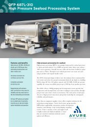
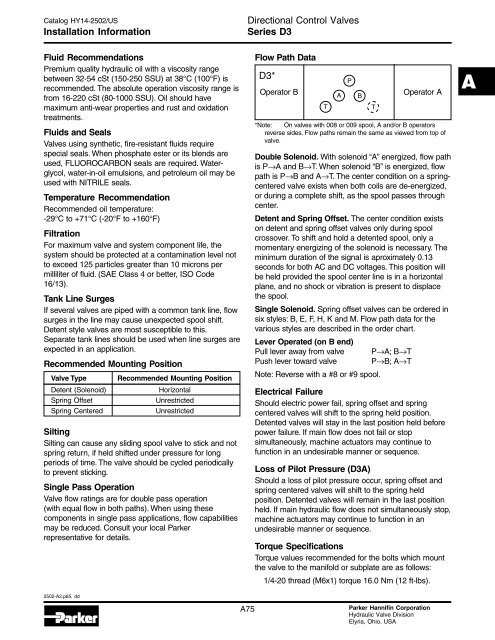
Catalog HY14-2502/USInstallation Information<s<strong>tr</strong>ong>Directional</s<strong>tr</strong>ong> <s<strong>tr</strong>ong>Con<strong>tr</strong>ol</s<strong>tr</strong>ong> ValvesSeries D3Fluid Re<s<strong>tr</strong>ong>com</s<strong>tr</strong>ong>mendationsPremium quality hydraulic oil with a viscosity rangebetween 32-54 cSt (150-250 SSU) at 38°C (100°F) isre<s<strong>tr</strong>ong>com</s<strong>tr</strong>ong>mended. The absolute operation viscosity range isfrom 16-220 cSt (80-1000 SSU). Oil should havemaximum anti-wear properties and rust and oxidation<strong>tr</strong>eatments.Fluids and SealsValves using synthetic, fire-resistant fluids requirespecial seals. When phosphate ester or its blends areused, FLUOROCARBON seals are required. Waterglycol,water-in-oil emulsions, and pe<strong>tr</strong>oleum oil may beused with NITRILE seals.Temperature Re<s<strong>tr</strong>ong>com</s<strong>tr</strong>ong>mendationRe<s<strong>tr</strong>ong>com</s<strong>tr</strong>ong>mended oil temperature:-29°C to +71°C (-20°F to +160°F)Fil<strong>tr</strong>ationFor maximum valve and system <s<strong>tr</strong>ong>com</s<strong>tr</strong>ong>ponent life, thesystem should be protected at a contamination level notto exceed 125 particles greater than 10 microns permilliliter of fluid. (SAE Class 4 or better, ISO Code16/13).Tank Line SurgesIf several valves are piped with a <s<strong>tr</strong>ong>com</s<strong>tr</strong>ong>mon tank line, flowsurges in the line may cause unexpected spool shift.Detent style valves are most susceptible to this.Separate tank lines should be used when line surges areexpected in an application.Re<s<strong>tr</strong>ong>com</s<strong>tr</strong>ong>mended Mounting PositionValve TypeDetent (Solenoid)Spring OffsetSpring CenteredRe<s<strong>tr</strong>ong>com</s<strong>tr</strong>ong>mended Mounting PositionHorizontalUnres<strong>tr</strong>ictedUnres<strong>tr</strong>ictedSiltingSilting can cause any sliding spool valve to stick and notspring return, if held shifted under pressure for longperiods of time. The valve should be cycled periodicallyto prevent sticking.Single Pass OperationValve flow ratings are for double pass operation(with equal flow in both paths). When using these<s<strong>tr</strong>ong>com</s<strong>tr</strong>ong>ponents in single pass applications, flow capabilitiesmay be reduced. Consult your local <s<strong>tr</strong>ong>Parker</s<strong>tr</strong>ong>representative for details.Flow Path DataD3*Operator B*Note: On valves with 008 or 009 spool, A and/or B operatorsreverse sides. Flow paths remain the same as viewed from top ofvalve.Double Solenoid. With solenoid “A” energized, flow pathis P→A and B→T. When solenoid “B” is energized, flowpath is P→B and A→T. The center condition on a springcenteredvalve exists when both coils are de-energized,or during a <s<strong>tr</strong>ong>com</s<strong>tr</strong>ong>plete shift, as the spool passes throughcenter.Detent and Spring Offset. The center condition existson detent and spring offset valves only during spoolcrossover. To shift and hold a detented spool, only amomentary energizing of the solenoid is necessary. Theminimum duration of the signal is aproximately 0.13seconds for both AC and DC voltages. This position willbe held provided the spool center line is in a horizontalplane, and no shock or vibration is present to displacethe spool.Single Solenoid. Spring offset valves can be ordered insix styles: B, E, F, H, K and M. Flow path data for thevarious styles are described in the order chart.Lever Operated (on B end)Pull lever away from valvePush lever toward valveNote: Reverse with a #8 or #9 spool.P→A; B→TP→B; A→TOperator AElec<strong>tr</strong>ical FailureShould elec<strong>tr</strong>ic power fail, spring offset and springcentered valves will shift to the spring held position.Detented valves will stay in the last position held beforepower failure. If main flow does not fail or stopsimultaneously, machine actuators may continue tofunction in an undesirable manner or sequence.Loss of Pilot Pressure (D3A)Should a loss of pilot pressure occur, spring offset andspring centered valves will shift to the spring heldposition. Detented valves will remain in the last positionheld. If main hydraulic flow does not simultaneously stop,machine actuators may continue to function in anundesirable manner or sequence.Torque SpecificationsTorque values re<s<strong>tr</strong>ong>com</s<strong>tr</strong>ong>mended for the bolts which mountthe valve to the manifold or subplate are as follows:1/4-20 thread (M6x1) torque 16.0 Nm (12 ft-lbs).A2502-A2.p65, ddA75<s<strong>tr</strong>ong>Parker</s<strong>tr</strong>ong> Hannifin CorporationHydraulic Valve DivisionElyria, Ohio, USA