Design of linear-phase FIR filters with minimum ... - ResearchGate
Design of linear-phase FIR filters with minimum ... - ResearchGate
Design of linear-phase FIR filters with minimum ... - ResearchGate

Create successful ePaper yourself
Turn your PDF publications into a flip-book with our unique Google optimized e-Paper software.
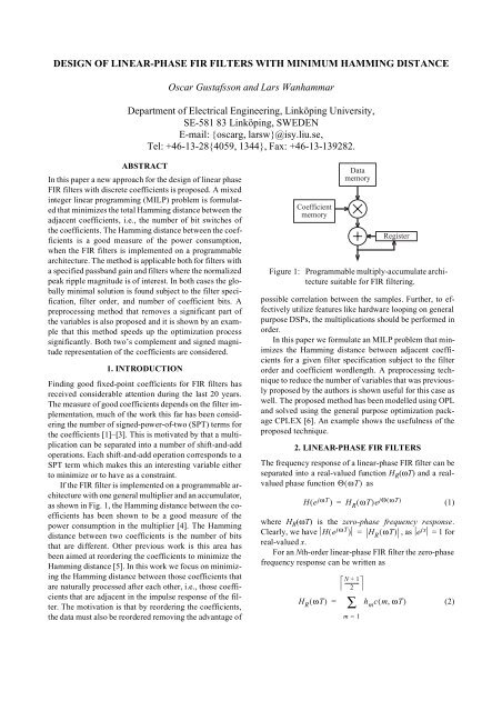
where cmωT ( , ) is a proper trigonometric function dependingon if the filter order is odd or even and if the impulseresponse is symmetric or anti-symmetric.Let the specifications <strong>of</strong> the filter be– δωT ( ) ≤ H R ( ωT) – D( ωT)≤ δωT ( )where D( ωT) is the desired magnitude and δ( ωT)is themaximum allowed ripple for a given angle ωT. Typically,D( ωT)is one in the passband and zero in the stopband <strong>of</strong>the filter.Note that (3), for each angle ωT, describes an inequalitythat is <strong>linear</strong> in the filter coefficients.When fixed-point coefficient is considered it is <strong>of</strong>tenuseful to allow a non-unity passband gain [7]. This can bedone by introducing a scaling factor, s, as– δωT ( ) ≤ H R ( ωT) ⁄ s – D( ωT)≤ δωT ( )The scaling factor is always larger than 0, so (4) can berewritten as(3)(4)sDωT [ ( ) – δ( ωT)] ≤ H R ( ωT) ≤ sDωT [ ( ) + δ( ωT)] (5)to obtain a <strong>linear</strong> inequality.3. PROPOSED DESIGN METHODThe objective is to form an MILP formulation <strong>of</strong> <strong>linear</strong><strong>phase</strong><strong>FIR</strong> filter design that minimizes the Hamming distancebetween adjacent coefficients. This will be done byfirst introducing a <strong>linear</strong> expression for the coefficientbits, where the bits corresponds to binary variables, x.Then, a second set <strong>of</strong> binary variables, y, will be introducedthat corresponds to if a bit position is switched betweentwo coefficients. As we want to minimize thenumber <strong>of</strong> switches, the optimization problem can be statedas minimizing the sum <strong>of</strong> all y variables.3.1. Two’s Complement CoefficientsTwo’s complement representation is commonly used inDSP applications. A coefficient, h m , <strong>of</strong> wordlength B expressedusing two’s complement can be written asB – 1h m = – x m,0 + x m, i 2 – ii = 1where x m, i ∈ { 0,1}. Thus, the coefficients <strong>of</strong> the <strong>FIR</strong> filtercan be described using a <strong>linear</strong> expression <strong>with</strong> binaryvariables.The Hamming distance between two coefficients isequal to the number <strong>of</strong> bits that are different. Introduce abinary variable, y m, i ∈ { 0,1}, as∑⎧1,x mi , ≠ x m + 1,iy m, i = ⎨0 , x x , m = 1 , …,M – 1⎩ mi , = m + 1 , i(6)(7)i.e., if bit i changes value between h m and h m + 1 , y m,i is oneotherwise it is zero. This can be expressed using <strong>linear</strong> expressionsas(8)Only one half <strong>of</strong> the impulse response needs to be considereddue to the symmetry <strong>of</strong> the magnitude <strong>of</strong> the coefficients.3.2. Signed Magnitude RepresentationAn alternative to two’s complement is signed magnituderepresentation. A B bit signed magnitude coefficient canbe written asHence, the first bit corresponds to the sign, while the remainingbits corresponds to the magnitude. Signed magnituderepresentation has a low switching probabilitywhen the numbers are small and <strong>with</strong> varying sign. Multiplicationis straight-forward using signed magnitude representation.The magnitudes can be multiplied usingunsigned multiplication, while the sign <strong>of</strong> the result is determined<strong>with</strong> a simple xor-operation <strong>of</strong> the sign bits <strong>of</strong>the multiplier and multiplicand. However, addition andsubtraction is more complex. It is possible to use two’scomplement representation <strong>of</strong> the data and signed magnituderepresentation <strong>of</strong> the coefficients. The multiplicationis then performed in two’s complement, <strong>with</strong> the coefficientalways being positive. The sign bit <strong>of</strong> the coefficientcontrols if the result <strong>of</strong> the multiplication should be addedor subtracted to the accumulator.Equation (9) can not be used directly in a <strong>linear</strong> formulation,instead for each coefficient a binary sign variables m is introduced along <strong>with</strong> B – 1 binary variables, x+m,i ,for positive coefficients and B – 1 binary variables, x–m,i ,for negative coefficients. The coefficient can now be writtenas<strong>with</strong> the constraintsandy m, i ≥ x mi , – x m + 1,iy m, i ≥ x m + 1,i – x mi ,⎧m = 1 ,…,M – 1, ⎨⎩ i = 0 , …,B – 1B – 1∑h m = (–1) x m, 0x mi , 2 – ii = 1h m=B – 1( x+ m,i – x–∑mi , )2 – ii = 1B – 1∑ x +m,i ≤ ( B – 1) ( 1 – s m ),1 ≤ m≤Mi = 1(9)(10)(11)
B – 1x–∑ m,i ≤ ( B – 1)s m , 1 ≤ m ≤Mi = 1(12)These constraints make sure that if the coefficient h m ispositive, s m = 0 and x– m,i = 0 for all i, and similarly, ifthe coefficient h m is negative, s m = 1 and x+ m,i = 0 for alli. The new variables are related to the formulation in (9) asx m, 0 = s mx m, i = x+ m,i + x –mi , , i = 1 , …,B – 1(13)The number <strong>of</strong> switched bits can now be expressed as in(8).3.3. Problem FormulationThe resulting optimization problem can for two’s complementrepresentation be formulated asminimizesubject toM – 1∑m = 1B – 1∑i = 0y m,isDωT [ ( ) – δ( ωT)] ≤ h m cmωT ( , )M∑m = 1(14)h m cmωT ( , ) ≤ sDωT [ ( ) + δ( ωT)]m = 1y m, i ≥ x m, i – x m + 1,iy m, i ≥ x m + 1,i – x m,iB – 1For signed magnitude representation the last row <strong>of</strong> (14)can be exchanged for (10)–(13).As the constraints are continuous in ωT it is necessaryformulate the constraint for discrete values <strong>of</strong> ωT. This iseasily done by selecting a number <strong>of</strong> values in the passbandand the stopband to obtain a grid <strong>of</strong> values whicheach leads to one constraint. As the specifications arechecked only in these points it is necessary to check the resultingtransfer function <strong>with</strong> a much finer grid to verifythat a valid coefficient set is obtained. If not, additionalpoints must be added to the constraints.If a prescribed passband gain is required the value <strong>of</strong> scan be fixed before the optimization starts. Note also thats must be larger than 0 as this otherwise would yield anoptimal solution <strong>with</strong> all variables equal to 0. In general itis possible to constrain s to be larger than 0.1, say, <strong>with</strong>out∑M∑h m = – x m,0 + x mi , 2 – ii = 1losing optimality in the solution. This is due to the factthat scaling s <strong>with</strong> 2 is equal to shifting each coefficientone step.4. REDUCING THE NUMBER OF VARIABLESIn the optimization problem in (14) the number <strong>of</strong> 0/1-variablesis (2M – 1)B and 3MB – M – B for two’s complementand signed magnitude representation, respectively.This number will be high for <strong>filters</strong> <strong>with</strong> stringent specificationsand the execution time will therefore be long.Hence, it is <strong>of</strong> interest to find ways to decrease the number<strong>of</strong> variables before the actual optimization starts. We willapply a method similar to that proposed in [3].To obtain the ranges for the coefficients it is possibleto use <strong>linear</strong> programming. The problem can be stated asfirst a separate maximization <strong>of</strong> each variable h m , subjectto (3). These values are assigned to the variables h ( ub)m .Then a minimization <strong>of</strong> each variable h m is performed andthe result is assigned the variables h( lb)m . However, thesevalues are for s = 1, so the possible range <strong>of</strong> s must befound to obtain the true bounds for h m .For a both a two’s complement and a signed-magnitudenumber <strong>with</strong> wordlength B, the maximal value forany positive coefficient is bounded approximately by one.A negative coefficient is bounded by minus one. To usethe complete range <strong>of</strong> the coefficients the absolute valuefor the coefficient <strong>with</strong> the largest magnitude should be atleast 1/2.The minimal value for the scaling factor is obtainedwhen the maximal absolute value for the upper or lowerbound times the scaling factor is 1/2. Hence(15)The maximal value for the scaling factor is when themaximal value <strong>of</strong> the coefficients <strong>minimum</strong> absolutebounds are 1. This is for coefficients that do not changesign. The upper bound is then(16)where the coefficients concerned are those that do notchange sign. This reasoning is only valid when at least onecoefficient have the same sign on its maximum and <strong>minimum</strong>value. However, this is the case for most <strong>filters</strong> unlessthe design margin is very large.New bounds on the coefficients can now be derived asands ( lb)1= -----------------------------------------------------------------------2max{ max{ h ( ub) m , h( lb)m }}s ( ub)1= -------------------------------------------------------------------max{ min{ h( ub) m , h ( lb)m }}ĥ ( ub)mmin( 1,h( ub )m s ( lb)) h ( ub) ⎧, m ≥ 0= ⎨max( – 1,h ( ub )m s ( ub)),h( ub) ⎩m < 0(17)
ĥ( lb)mmin( 1,h( lb )m s ( ub)) h ( lb) ⎧, m ≥ 0= ⎨max( – 1,h ( lb )m s ( lb)),h ( lb) ⎩m < 0(18)If the passband gain is specified we have s (ub) = s (lb) = s s ,where s s is the specified passband gain. Finally, the followinginequality is obtainedĥ ( lb ) m ≤ h ≤ ĥ ( ub )m m(19)This inequality can either be added to the constraints <strong>of</strong>the optimization or used to preevaluate possible values <strong>of</strong>the variables. Here, (19) is utilized to determine which bitsthat do have a fixed value and remove these from the optimizationproblem. This can be done by searching all possiblevalues for the filter coefficient and keep track <strong>of</strong>which values the bits assume. All variables that only assignone value can be fixed and thereby removed from theoptimization problem.As will be shown in the example below, the number <strong>of</strong>variables that can be removed depends on the availabledesign margin and the representation used. The number <strong>of</strong>variables that can be removed are in general not dependenton the coefficient wordlength, as typically it is the mostsignificant bits <strong>of</strong> a coefficient that are fixed. However,the relative savings will be smaller when the wordlengthis increased.5. EXAMPLETo show the usefulness <strong>of</strong> the proposed idea we will considerone filter design example. The filter under considerationis a lowpass filter <strong>with</strong> passband edge at 0.3π andstopband edge at 0.5π. The allowed ripple is 0.001 in boththe passband and the stopband. A filter order <strong>of</strong> 33 is used.Hence, there are 17 coefficients to be designed. Using theRemez exchange algorithm and rounding, 15 coefficientbits are required to satisfy the specification. For two’scomplement representation the sum <strong>of</strong> the Hamming distancesbetween subsequent coefficients are 118. Using theproposed design method a solution <strong>with</strong> 13 bits can befound <strong>with</strong> a total Hamming distance <strong>of</strong> 79. The originaloptimization problem has 448 variables, while after theproposed preprocessing it has 292 variables. Thus, a significantspeed-up was obtained for the solution. The problemwas solved on an AMD Athlon 1800+ <strong>with</strong> 1.5 GB <strong>of</strong>RAM. The pre-processing took approximately 30 s, whilethe MILP stage took 55 minutes. For signed magnituderepresentation, the rounded solution has a total Hammingdistance <strong>of</strong> 78. The original optimization problem has 652variables, while after preprocessing 255 variables remain.The optimized solution has a total Hamming distance <strong>of</strong>60. For this problem the MILP stage took approximately150 minutes. The magnitude responses for the three designed<strong>filters</strong> are shown in Fig. 2.|H(e jωT )| [dB]0−10−20−30−40−50−60−70−800 0.2π 0.4π 0.6π 0.8π πωT [rad]Figure 2: Magnitude responses for example filterdesigned using (solid) Remez and rounding,(dashed) proposed approach <strong>with</strong>two’s complement representation, and(dotted) proposed approach <strong>with</strong> signedmagnitude representation.6. CONCLUSIONSIn this paper a mixed integer <strong>linear</strong> programming problemfor design <strong>of</strong> <strong>linear</strong>-<strong>phase</strong> <strong>FIR</strong> <strong>filters</strong> <strong>with</strong> <strong>minimum</strong> Hammingdistance between adjacent coefficients was formulated.It has been shown in earlier work that the Hammingdistance is a good measure <strong>of</strong> the power consumption fora programmable <strong>FIR</strong> filter. A preprocessing technique toremove 0/1-variables, and, thus, decrease the solutiontime, was discussed. Both two’s complement and signedmagnitude representation were considered. A design exampleshowed the usefulness <strong>of</strong> the proposed method.7. REFERENCES[1] T. Saramäki and J. Yli-Kaakinen, “<strong>Design</strong> <strong>of</strong> digital <strong>filters</strong>and filter banks by optimization: applications,” in Proc. XEuropean Signal Processing Conf., Tampere, Finland,Sept. 4–8, 2000.[2] H. Samuli, “An improved search algorithm for the design<strong>of</strong> multiplierless <strong>FIR</strong> <strong>filters</strong> <strong>with</strong> powers-<strong>of</strong>-two coefficients,”IEEE Trans. Circuits Syst., vol. 36, pp. 1044–1047, July 1989.[3] O. Gustafsson, H. Johansson, and L. Wanhammar, “AnMILP approach for the design <strong>of</strong> <strong>linear</strong>-<strong>phase</strong> <strong>FIR</strong> <strong>filters</strong><strong>with</strong> <strong>minimum</strong> number <strong>of</strong> signed-power-<strong>of</strong>-two terms”, inProc. European Conf. Circuit Theory <strong>Design</strong>, Espoo, Finland,Aug. 28–31, 2001.[4] M. Mehendale, S. D. Sherlekar, and G. Venkatesh, “Coefficientoptimization for low power realization <strong>of</strong> <strong>FIR</strong> <strong>filters</strong>,”in Proc. IEEE Workshop VLSI Signal Processing,1995, pp. 352–361.[5] P. K. Merakos et al, “A novel transformation for reduction<strong>of</strong> switching activity in <strong>FIR</strong> <strong>filters</strong> implementation,” inProc. Int. Conf. Digital Signal Processing, 1997, vol. 2,pp. 653–656.[6] ILOG, http://www.ilog.com/, June 2002.[7] Y. C. Lim, “<strong>Design</strong> <strong>of</strong> discrete-coefficient-value <strong>linear</strong><strong>phase</strong> <strong>FIR</strong> <strong>filters</strong> <strong>with</strong> optimum normalized peak ripplemagnitude,” IEEE Trans. Circuits Syst., vol. 37, pp.1480–1486, Dec. 1990.