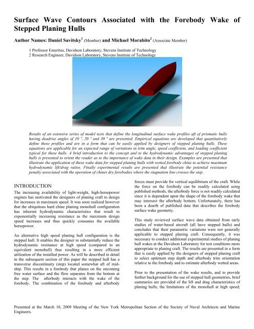
Surface Wave Contours Associated with the Forebody Wake of Stepped ...
Surface Wave Contours Associated with the Forebody Wake of Stepped ...
Surface Wave Contours Associated with the Forebody Wake of Stepped ...

Create successful ePaper yourself
Turn your PDF publications into a flip-book with our unique Google optimized e-Paper software.
<strong>Surface</strong> <strong>Wave</strong> <strong>Contours</strong> <strong>Associated</strong> <strong>with</strong> <strong>the</strong> <strong>Forebody</strong> <strong>Wake</strong> <strong>of</strong><strong>Stepped</strong> Planing HullsAuthor Names: Daniel Savitsky 1 (Member) and Michael Morabito 2 (Associate Member)1 Pr<strong>of</strong>essor Emeritus, Davidson Laboratory, Stevens Institute <strong>of</strong> Technology2 Research Engineer, Davidson Laboratory, Stevens Institute <strong>of</strong> TechnologyResults <strong>of</strong> an extensive series <strong>of</strong> model tests that define <strong>the</strong> longitudinal surface wake pr<strong>of</strong>iles aft <strong>of</strong> prismatic hullshaving deadrise angles <strong>of</strong> 10 º, 20 º and 30 º are presented. Empirical equations are developed that quantitativelydefine <strong>the</strong>se pr<strong>of</strong>iles and are in a form that can be easily applied by designers <strong>of</strong> stepped planing hulls. Theseequations are applicable for an expected range <strong>of</strong> variations in trim angle, speed coefficient, and loading coefficienttypical for <strong>the</strong>se hulls. A brief introduction to <strong>the</strong> concept and to <strong>the</strong> hydrodynamic advantages <strong>of</strong> stepped planinghulls is presented to orient <strong>the</strong> reader as to <strong>the</strong> importance <strong>of</strong> wake data in <strong>the</strong>ir design. Examples are presented thatillustrate <strong>the</strong> application <strong>of</strong> <strong>the</strong>se wake data for stepped planing hulls <strong>with</strong> wetted forebody chine to achieve maximumhydrodynamic lift/drag ratios. Finally experimental results are presented that illustrate <strong>the</strong> potential resistancepenalty associated <strong>with</strong> <strong>the</strong> operation <strong>of</strong> chines dry forebodies where <strong>the</strong> stagnation line crosses <strong>the</strong> step.INTRODUCTIONThe increasing availability <strong>of</strong> light-weight, high-horsepowerengines has motivated <strong>the</strong> designers <strong>of</strong> planing craft to designfor increases in maximum speed. It was soon realized howeverthat <strong>the</strong> ubiquitous hard chine planing monohull configurationhas inherent hydrodynamic characteristics that result inexponentially increasing resistance as <strong>the</strong> maximum designspeed increases and thus quickly consumes <strong>the</strong> availablehorsepower.An alternative high speed planing hull configuration is <strong>the</strong>stepped hull. It enables <strong>the</strong> designer to substantially reduce <strong>the</strong>hydrodynamic resistance at high speed (compared to anequivalent monohull) thus resulting in a more efficientutilization <strong>of</strong> <strong>the</strong> installed power. As will be described in detailin <strong>the</strong> subsequent section <strong>of</strong> this paper <strong>the</strong> stepped hull has atransverse discontinuity (step) located somewhat aft <strong>of</strong> midship.This results in a forebody that planes on <strong>the</strong> oncomingfree water surface and <strong>the</strong> flow separates from <strong>the</strong> bottom at<strong>the</strong> step. The afterbody interacts <strong>with</strong> <strong>the</strong> wake <strong>of</strong> <strong>the</strong>forebody. The combination <strong>of</strong> <strong>the</strong> forebody and afterbodyforces must provide for vertical equilibrium <strong>of</strong> <strong>the</strong> craft. While<strong>the</strong> force on <strong>the</strong> forebody can be readily calculated usingpublished methods, <strong>the</strong> afterbody force is not readily calculatedsince it is dependent upon <strong>the</strong> shape <strong>of</strong> <strong>the</strong> forebody wake thatmay intersect <strong>the</strong> afterbody bottom. Unfortunately, <strong>the</strong>re hasbeen a dearth <strong>of</strong> published data that describes <strong>the</strong> forebodysurface wake geometry.This study reviewed surface wave data obtained from earlystudies <strong>of</strong> water-based aircraft (all have stepped hulls) andconcludes that <strong>the</strong>ir parametric variations were not generallyapplicable to stepped planing craft. Consequently, it wasnecessary to conduct additional experimental studies <strong>of</strong> planinghull wakes at <strong>the</strong> Davidson Laboratory for test conditions moreappropriate to planing craft. The results are presented in a formthat is easily applied by <strong>the</strong> designers <strong>of</strong> stepped planing craftto select optimum step depth and afterbody trim orientationrelative to <strong>the</strong> forebody and to estimate afterbody wetted areas.Prior to <strong>the</strong> presentation <strong>of</strong> <strong>the</strong> wake results, and to providefur<strong>the</strong>r background for <strong>the</strong> use <strong>of</strong> stepped hull geometries, briefsummaries are provided <strong>of</strong> <strong>the</strong> lift and drag characteristics <strong>of</strong>planing hulls; <strong>the</strong> limitations <strong>of</strong> <strong>the</strong> monohull at high speed;Presented at <strong>the</strong> March 10, 2009 Meeting <strong>of</strong> <strong>the</strong> New York Metropolitan Section <strong>of</strong> <strong>the</strong> Society <strong>of</strong> Naval Architects and MarineEngineers.
and finally how <strong>the</strong> stepped hull overcomes <strong>the</strong>se limitations.A hull configuration having a length <strong>of</strong> 32 ft (9.8m), adisplacement <strong>of</strong> 10,000 lbs (4546 kg) and operating in <strong>the</strong>chines wetted condition is used to illustrate <strong>the</strong> results. Futurestudies <strong>of</strong> <strong>the</strong> chines dry operating condition, such as iscommon in multi-step high speed racing craft, are planned.It is believed that this background may be useful inunderstanding <strong>the</strong> necessity for defining <strong>the</strong> forebody surfacewake geometries in <strong>the</strong> design <strong>of</strong> stepped hulls.IMPORTANCE OF TRIM ANGLE ON THEHYDRODYNAMIC RESISTANCE OF PLANINGCRAFTOne <strong>of</strong> <strong>the</strong> most significant parameters that influence <strong>the</strong>performance <strong>of</strong> a planing craft is <strong>the</strong> equilibrium trim anglewhich varies <strong>with</strong> speed. It has a major effect on resistance,seakeeping, porpoising, and lateral stability. Each <strong>of</strong> <strong>the</strong>seperformance characteristics is worthy <strong>of</strong> a separate discussion.However, for <strong>the</strong> purposes <strong>of</strong> this paper only <strong>the</strong> effect <strong>of</strong> trimangle on hydrodynamic resistance is considered. It is shownthat <strong>the</strong> particular relationship between trim and resistancenaturally leads to adaptation <strong>of</strong> <strong>the</strong> stepped hull form at highplaning speeds.To best illustrate <strong>the</strong> dependence <strong>of</strong> resistance on trim angle,use is made <strong>of</strong> <strong>the</strong> planing lift and resistance equations forprismatic hulls from Savitsky (1964). These are repeatedbelow:Lift Coefficient <strong>of</strong> Zero Deadrise <strong>Surface</strong>:Cl o = Δ/ 0.50 ρ V 2 B 2= τ 1.1 ( 0.120 λ ½ + 0.0055 λ 5/2 / C V 2 ) (1)Lift Coefficient <strong>of</strong> Deadrise <strong>Surface</strong>:Cl β = Cl o –0.0065 β Cl o 0.60 (2)Hydrodynamic Resistance (exclusive <strong>of</strong> whisker-spray drag):R T = Δ tan τ + 0.50ρ V 2 λ B 2 C f (3)For <strong>the</strong> purpose <strong>of</strong> this illustration, consider a planing craft thathas <strong>the</strong> following geometry; loading and speed:LOA = 32 ft (9.8 m)Chine Beam (B) = 7.8 ft (2.4 m)Deadrise angle (β) = 12.5ºDisplacement (Δ) = 10,000 lbs (4546 kg)Velocity (Vk) = 40 knotsCl β = 0.036Roughness allowance = 0Now consider <strong>the</strong> planing surface free to heave but runningover a range <strong>of</strong> fixed trim angles. Using <strong>the</strong> above equations,<strong>the</strong> wetted area (λ B 2 ) and <strong>the</strong> total resistance/ displacementratio (R T /Δ) can be calculated as a function <strong>of</strong> trim angle. Theresults are plotted on Fig. 1. (Similar calculations can be madefor o<strong>the</strong>r deadrise angles; width <strong>of</strong> beam; displacements; andspeeds.) Although <strong>the</strong> absolute values <strong>of</strong> <strong>the</strong> results will bedifferent, <strong>the</strong> general conclusions on <strong>the</strong> effects <strong>of</strong> trim angleon wetted area and total resistance/displacement ratio will beessentially similar to that shown on Fig.1.Fig. 1: Calculated Wetted Area and R T /Δ vs. Trim AngleVariation <strong>of</strong> Wetted Area <strong>with</strong> Trim AngleReferring to Fig. 1 it is to be noted that <strong>the</strong> wetted surface areavaries inversely as an exponential power <strong>of</strong> trim angle. Forexample, decreasing <strong>the</strong> trim angle from 4º to 2º nearlyquadruples <strong>the</strong> wetted surface for a prismatic hull. This issignificant since <strong>the</strong> viscous resistance component increaseslinearly <strong>with</strong> <strong>the</strong> size <strong>of</strong> <strong>the</strong> wetted area (neglecting <strong>the</strong>relatively small change in C f as <strong>the</strong> wetted length increases).Fur<strong>the</strong>r, for trim angles less than 5º <strong>the</strong>re is a rapid increase inwetted area as <strong>the</strong> trim is decreased, while for larger trimangles <strong>the</strong>re is only a moderate decrease in wetted surface as<strong>the</strong> trim increases.Variation <strong>of</strong> R T /Δ <strong>with</strong> Trim AngleAs is well known to designers <strong>of</strong> planing craft, <strong>the</strong> totalhydrodynamic resistance (exclusive <strong>of</strong> whisker spray drag) is<strong>the</strong> sum <strong>of</strong> <strong>the</strong> pressure drag (Δ tan τ ) that increases <strong>with</strong>increasing trim angle and <strong>the</strong> viscous resistance developed by<strong>the</strong> wetted bottom area which decreases <strong>with</strong> increasing trimangle. For <strong>the</strong> current example, it is seen from Fig.1 that <strong>the</strong>sum <strong>of</strong> <strong>the</strong>se two components attains a minimum value in <strong>the</strong>proximity <strong>of</strong> 4º and increases for smaller and larger trimangles. The trim angle for minimum resistance increasesslightly as <strong>the</strong> deadrise angle is increased. For <strong>the</strong> present 12.5ºdeadrise angle it is seen that decreasing <strong>the</strong> trim angle from 4ºto 2º will nearly double <strong>the</strong> hydrodynamic resistance. Practicalhull forms have a longitudinally convex bow curvature that, ifwetted at low trim angles, will add additional form resistance.Designers are certainly aware <strong>of</strong> this trim effect on resistance
and attempt to locate <strong>the</strong> LCG to achieve optimum trim anglesand hence minimum resistance/displacement ratios. Of coursethis is not always achievable, particularly <strong>with</strong> high-speedplaning monohulls. Some designers will introduce a “rocker”geometry at <strong>the</strong> transom in order to increase <strong>the</strong> running trimangle-but this alternation is usually not completely effective.LIMITATIONS OF PLANING MONOHULLS ATHIGH SPEEDUsing <strong>the</strong> planing monohull hull geometry and dimensionspreviously listed, but now locating <strong>the</strong> LCG at 14.4 ft forward<strong>of</strong> <strong>the</strong> transom and allowing <strong>the</strong> craft to have freedom in heaveand trim, <strong>the</strong> equilibrium values <strong>of</strong> trim and resistance, asfunction <strong>of</strong> speed, can be calculated using <strong>the</strong> method fromSavitsky (1964). These results are shown on Fig. 2. For <strong>the</strong>purpose <strong>of</strong> presenting a simple illustration, <strong>the</strong> added resistancedue to <strong>the</strong> whisker spray (Savitsky, 2007) is omitted. This willnot change <strong>the</strong> conclusions <strong>of</strong> <strong>the</strong> present discussion.Trim Variation <strong>with</strong> SpeedNote from Fig.2 that, as is usual, <strong>the</strong> equilibrium trim angledecreases <strong>with</strong> increasing speed. At a planing speed <strong>of</strong> 20knots, <strong>the</strong> trim angle is approximately 3º and, as shown onFig.1, this results in an essentially minimum value <strong>of</strong>resistance/displacement ratio. As speed increases, <strong>the</strong>equilibrium trim decreases and attains a value <strong>of</strong>approximately 1º at 60 knots. (well below <strong>the</strong> optimum trimangle) The calculation method (Savitsky, 1964) will also showthat <strong>the</strong> wetted keel length will exceed <strong>the</strong> LOA <strong>of</strong> this hull at60 knots.—this will cause some bow penetration into <strong>the</strong>oncoming fluid and hence result in an added form resistance.This is an undesirable operating condition. To avoid bowwetting <strong>the</strong> wetted keel length should be less thanapproximately 0.90 LWL. The calculation method (Savitsky,1964) indicates that this will occur at a speed <strong>of</strong> 40 knots. Atthis speed <strong>the</strong> trim angle is 2º—unfortunately, as shown onFig. 1 this is substantially less than <strong>the</strong> optimum trim angle <strong>of</strong>approximately 4º.Resistance/Displacement Ratio Variation <strong>with</strong>SpeedAs shown on Fig. 2 <strong>the</strong> resistance/displacement ratio increasesrapidly <strong>with</strong> increasing speed and <strong>the</strong> associated decrease intrim. At 20 knots, R T /Δ = 0.10—a most acceptable value. At40 knots, R T /Δ = 0.20—an unavoidable value that may have tobe accepted by default. At 60 knots, R T /Δ = 0.35—acompletely unacceptably value.Fig. 2 Calculated Typical Trim R T /Δ and vs. Speed -MonohullSummarySince <strong>the</strong> equilibrium trim angle <strong>of</strong> planing monohullsnaturally decrease <strong>with</strong> increasing speed, <strong>the</strong>y quickly attainvalues that are well below <strong>the</strong> optimum trim angle required forminimum resistance. This may be partially alleviated bydesigning <strong>with</strong> a fur<strong>the</strong>r aft located LCG or incorporating some“rocker” at <strong>the</strong> transom. If <strong>the</strong>se are not feasible or totallyeffective, an alternative option is <strong>the</strong> use <strong>of</strong> a stepped planinghull that will allow for high speed operation at a more optimumtrim angle. The next section discusses <strong>the</strong> geometric featuresand resistance characteristics <strong>of</strong> <strong>the</strong> stepped hull and <strong>the</strong>importance <strong>of</strong> providing forebody surface wake pr<strong>of</strong>iles forproper total design <strong>of</strong> <strong>the</strong>se hulls.STEPPED PLANING HULLS DESIGNEDTOACHIEVE MAXIMUM LIFT/DRAG RATIOAT HIGH SPEEDThis brief discussion is not intended to provide a detaileddesign procedure for stepped hulls. It merely presents anoverview <strong>of</strong> <strong>the</strong> hydrodynamic influences that must beconsidered when designing <strong>the</strong>se hulls for minimumhydrodynamic resistance at high speed. This may be in contrast<strong>with</strong> <strong>the</strong> multi-step racing hulls that are designed for maximum
speed and stability. It is expected that at some future date <strong>the</strong>performance <strong>of</strong> <strong>the</strong>se multi-step racing stepped hulls will bebetter understood and <strong>the</strong>ir hydrodynamic lift/drag ratiosdocumented.The previous discussions have shown that <strong>the</strong> high speedplaning monohull has relatively large hydrodynamic resistancedue to its inherent characteristic <strong>of</strong> running at trim angles wellbelow <strong>the</strong> optimum trim angle required for minimumresistance at high planing speeds. The stepped hull overcomesthis deficiency in <strong>the</strong> following manner:The hull is split transversally at a position somewhat aft <strong>of</strong> midship creating a forebody and afterbody. The afterbody keel isslightly raised above <strong>the</strong> forebody keel creating a “step” in <strong>the</strong>pr<strong>of</strong>ile view (see Fig.3) hence <strong>the</strong> name “stepped hull”. Inaddition, <strong>the</strong> keel <strong>of</strong> <strong>the</strong> afterbody may be oriented at anappropriate angle relative to forebody keel to achieve a desiredintersection <strong>with</strong> <strong>the</strong> forebody wake. The water flow from <strong>the</strong>forebody separates from <strong>the</strong> bottom at <strong>the</strong> step location andclears most <strong>of</strong> <strong>the</strong> afterbody bottom. The contour <strong>of</strong> thisforebody wake governs <strong>the</strong> step height and angle <strong>of</strong> <strong>the</strong>afterbody. It is this forebody wake shape that is <strong>the</strong> primarysubject <strong>of</strong> this report.Typically approximately 90% <strong>of</strong> <strong>the</strong> total weight <strong>of</strong> a steppedhull is supported by <strong>the</strong> forebody since its lift/drag ratio isdesigned to be as large as possible. The remainder <strong>of</strong> <strong>the</strong>weight is supported by <strong>the</strong> afterbody or a stern appendage thatpenetrates <strong>the</strong> forebody wake. This appendage can be madeadjustable to control <strong>the</strong> trim angle as speed is varied. It shouldalso provide pitch damping to avoid porpoising. The LCGposition is in <strong>the</strong> forebody region and slightly forward <strong>of</strong> <strong>the</strong>step. This limits <strong>the</strong> extent <strong>of</strong> <strong>the</strong> planing area on <strong>the</strong> forebody.Thus, to support 90% <strong>of</strong> <strong>the</strong> total load on a relatively smallbottom area, <strong>the</strong> trim angle <strong>of</strong> <strong>the</strong> forebody must be larger thanthat <strong>of</strong> a monohull which uses both <strong>the</strong> forebody and afterbodyplaning areas. This is <strong>the</strong> key to attractiveness <strong>of</strong> <strong>the</strong> steppedhull—at high speed it can be designed to operate at <strong>the</strong> trimangle for minimum hydrodynamic resistance. To fur<strong>the</strong>rincrease <strong>the</strong> lift/drag ratio <strong>of</strong> <strong>the</strong> forebody, its trailing edge (at<strong>the</strong> step) can ei<strong>the</strong>r be cambered longitudinally (Clement andKoelbel, 1992) or fitted <strong>with</strong> an adjustable angle trailing edgeflap. The effectiveness <strong>of</strong> this later modification is discussedbelow.Estimate <strong>of</strong> <strong>the</strong> Performance <strong>of</strong> a <strong>Stepped</strong> HullTo illustrate <strong>the</strong> advantage <strong>of</strong> a stepped planing hull at highspeed, <strong>the</strong> monohull shown in Fig. 1 is reconfigured into anequivalent stepped hull as shown in Fig. 3. The totaldisplacement, 10,000 lbs (4546 kg), <strong>the</strong> LOA, 32 ft (9.8 m), <strong>the</strong>chine beam, 7.8 ft (2.4 m) and deadrise angle, 12.5º, remain <strong>the</strong>same. The afterbody length is taken to be 13.5 ft (4.1 m). Theforebody load (Δ f ) is 0.90 x 10,000 = 9,000 lbs (4091 kg). It isassumed that <strong>the</strong> remaining 1,000 lbs (455 kg) is carried by <strong>the</strong>afterbody or a submerged or surface piercing hydr<strong>of</strong>oil that isattached to <strong>the</strong> transom and penetrates <strong>the</strong> forebody wake.Fig. 3 Dimensions <strong>of</strong> Equivalent <strong>Stepped</strong> HullB = 7.8 ft, β = 12.5°For <strong>the</strong> purposes <strong>of</strong> this illustration, <strong>the</strong> afterbody resistance isassumed to be small compared to <strong>the</strong> forebody so <strong>the</strong>calculated results will be for <strong>the</strong> forebody which supports aload <strong>of</strong> 9,000 lbs (4091 kg). The afterbody load is taken to belocated approximately 1 ft (0.3 m) forward <strong>of</strong> <strong>the</strong> transom—this will be demonstrated in <strong>the</strong> illustrative example providedin a latter section <strong>of</strong> this paper. For pitch equilibrium <strong>the</strong>longitudinal location (Lo) <strong>of</strong> <strong>the</strong> 9,000 lb (4091 kg) load on <strong>the</strong>forebody relative to <strong>the</strong> load on <strong>the</strong> afterbody is obtained bytaking moments about <strong>the</strong> resultant afterbody load location.Thus:10,000 x 14.4 = 9,000 x LoThus: Lo = 16 ft (4.9 m)Hence, <strong>the</strong> center <strong>of</strong> pressure <strong>of</strong> <strong>the</strong> 9,000 lb (4091 kg) load is16.0 - 12.5 = 3.5 ft (1.1 m) forward <strong>of</strong> <strong>the</strong> step. This is animportant dimension in <strong>the</strong> design <strong>of</strong> <strong>the</strong> stepped hull since <strong>the</strong>stagnation line on <strong>the</strong> forebody should intersect <strong>the</strong> chineahead <strong>of</strong> <strong>the</strong> step. Given <strong>the</strong> 9,000 lbs (4091 kg) acting 3.5 ft(1.1 m) forward <strong>of</strong> <strong>the</strong> step, <strong>the</strong> simplified format equations inSavitsky (1964) can be used to calculate <strong>the</strong> orientation <strong>of</strong> <strong>the</strong>stagnation line relative to <strong>the</strong> keel and also <strong>the</strong> keel and chinewetted lengths relative to <strong>the</strong> step. If <strong>the</strong> stagnation lineintersects <strong>the</strong> step, <strong>the</strong> heavy main spray, that originates at thatpoint will impinge upon <strong>the</strong> bottom <strong>of</strong> <strong>the</strong> afterbody and resultin a substantial increase in resistance.Performance Without Flaps Using <strong>the</strong> performanceestimating equations for <strong>the</strong> forebody <strong>with</strong>out flaps (Savitsky,1964) <strong>the</strong> calculated equilibrium trim angle and resistance/displacement ratio are plotted on Fig. 4. (solid symbols) andare compared <strong>with</strong> <strong>the</strong> monohull results (curves). A transversestep was used in this illustration since it was shown in Savitskyand Brown (1976) that while a reentrant vee-transom, such assuggested by Clement and Koelbel (1992), can attain higheraspect ratios, <strong>the</strong> lift-drag ratio <strong>of</strong> <strong>the</strong> reentrant step issomewhat smaller than that <strong>of</strong> a transverse step that has <strong>the</strong>same wetted area.
The calculations for <strong>the</strong> stepped hull are limited to speeds lessthan 40 knots (F ∇ =5.2) and greater than 30 knots (F ∇ = 3.9). Atspeeds greater than 40 knots, <strong>the</strong> trim angle will decrease and<strong>the</strong> stagnation line will cross <strong>the</strong> step. The main spray will thusimpinge on <strong>the</strong> afterbody bottom <strong>with</strong> an un-quantifiedassociated increase in resistance. This is an undesirableoperating condition, however it can be alleviated by anadjustable hydr<strong>of</strong>oil attached to <strong>the</strong> stern than will control <strong>the</strong>trim. At speeds less than 30 knots, <strong>the</strong> flow from <strong>the</strong> forebodymay not completely ventilate at <strong>the</strong> step. This will result in anincreased form drag <strong>of</strong> <strong>the</strong> forebody which, at <strong>the</strong> present time,cannot be easily calculated. It is likely that, at speeds less than30 knots, <strong>the</strong> resistance <strong>of</strong> <strong>the</strong> stepped hull will be greater thatthat <strong>of</strong> <strong>the</strong> equivalent monohull.From Fig. 4 it is seen that <strong>the</strong> running trim angles <strong>of</strong> <strong>the</strong>stepped hull are larger than those <strong>of</strong> <strong>the</strong> monohull and well<strong>with</strong>in <strong>the</strong> favorable range <strong>of</strong> trim angles as shown on Fig. 1.At an operating speed <strong>of</strong> 40 knots, <strong>the</strong> trim angle is 4.3º and<strong>the</strong> R T /Δ for <strong>the</strong> stepped hull is nearly ½ that <strong>of</strong> <strong>the</strong> monohull.This is a significant improvement in performance that justifiesconsideration <strong>of</strong> <strong>the</strong> stepped hull for high speed operation. At30 knots, (F ∇ = 3.9) <strong>the</strong> R T /Δ for both hull forms are nearlyequal, so that <strong>the</strong> more simply constructed monohull would be<strong>the</strong> desired hull form.Performance With Controlled <strong>Forebody</strong> Transom FlapsClement and Koelbel (1992) recommended that <strong>the</strong> afterbottom <strong>of</strong> <strong>the</strong> forebody have longitudinal camber that isdefined by a Johnson 3 term pr<strong>of</strong>ile (Johnson, 1961).Since <strong>the</strong> primary curvature <strong>of</strong> <strong>the</strong> cambered section is along asmall area just forward <strong>of</strong> <strong>the</strong> trailing edge, it was speculatedthat a deflected flap located at <strong>the</strong> trailing edge <strong>of</strong> <strong>the</strong> forebodymay have similar beneficial effects on improving <strong>the</strong> lift/dragratio. Studies <strong>of</strong> <strong>the</strong> effectiveness <strong>of</strong> transom flaps installed onplaning craft are reported in Savitsky and Brown (1976). Itwas shown that for a fixed trim, load and speed <strong>the</strong> drag/liftratio was reduced as <strong>the</strong> deflected flap area was increased.Savitsky and Brown (1976) also presents methods forcalculating <strong>the</strong> flap effectiveness on a planing craft. Using<strong>the</strong>se methods, a flap was selected for <strong>the</strong> stepped hull justdescribed. The dimensions and deflection <strong>of</strong> <strong>the</strong> flap whichwas attached to <strong>the</strong> hull bottom were:Full span = 7.8 ft (2.4 m)Chord = 0.40 ft (0.12 m)Deflection: 2.5º @ 40 knots10.0º @ 30 knotsThe flap deflection angles were selected to assure that <strong>the</strong>stagnation line on <strong>the</strong> forebody intersected <strong>the</strong> chine at eachtest speed.It is important to understand that <strong>the</strong> objective <strong>of</strong> this briefintroduction to stepped planing hulls is not to compare <strong>the</strong>performance <strong>of</strong> a transverse step <strong>with</strong> <strong>the</strong> re-entrant andlongitudinally cambered step described by Clement andKoelbel. Each has <strong>the</strong>ir advantages and disadvantages. Ra<strong>the</strong>r,since <strong>the</strong> primary objective <strong>of</strong> this study is to supply wakedata, <strong>the</strong> transverse step was used as a simple illustration toemphasize <strong>the</strong> need for such data when designing steppedhulls.Using <strong>the</strong> methods <strong>of</strong> Savitsky (1964) and Savitsky and Brown(1976), <strong>the</strong> equilibrium trim angles and R T /Δ values werecalculated and are presented on Fig. 4. As expected, <strong>the</strong> flapreduced <strong>the</strong> running trim and, in addition, reduced R T /Δ at 30and 40 knots At <strong>the</strong>se speeds, <strong>the</strong> R T /Δ was 0.10, a mostsignificant improvement compared to <strong>the</strong> planing monohull. Itis important to note that, while <strong>the</strong> deflected flap reduced <strong>the</strong>trim angle at 40 knots, this lower trim angle was still <strong>with</strong> in<strong>the</strong> acceptable trim range as shown on Fig. 1. It is suggestedthat a stepped planing hull may be designed <strong>with</strong>out active trimcontrol if <strong>the</strong> LCG is located so that <strong>the</strong> craft operates atoptimum trim at <strong>the</strong> design high speed. For modest changes intrim, due to changes in speed, <strong>the</strong> R T /Δ varies very little.Fig. 4: Calculated Trim and R T /Δ vs. Speed – Monohull vs.<strong>Stepped</strong> HullsComparison <strong>of</strong> Wetted Areas and Performance<strong>of</strong> a <strong>Stepped</strong> Hull vs. a MonohullFigures 5(a-c) present this comparison for a 40 knot planingspeed. The results are self explanatory. Note that <strong>the</strong> afterbody
forces are not considered. Although not discussed in this paperit is likely that, <strong>with</strong>out an afterbody contribution to lift andespecially pitch damping, <strong>the</strong> forebody will porpoise. This canbe demonstrated by comparing <strong>the</strong> tabulated equilibrium trimangles <strong>with</strong> <strong>the</strong> porpoising limit criteria given in Savitsky(1964).Fig. 5(c) Comparison <strong>of</strong> Trim and Wetted Areas<strong>Stepped</strong> Hull With Flap on Transom <strong>of</strong> <strong>Forebody</strong>(<strong>Forebody</strong> Load = 9,000 lb; V K = 40; F V = 5.2)Fig. 5(a) Comparison <strong>of</strong> Trim and Wetted AreasMonohull(Δ = 10,000 lb; V K = 40; F V = 5.1)SummaryThe stepped planing hull configuration <strong>of</strong>fers significantreductions in total resistance at F ∇ greater than approximately5.0 as compared to a similar planing monohull.Unfortunately, <strong>the</strong>re has been a dearth <strong>of</strong> data on <strong>the</strong> shape <strong>of</strong><strong>the</strong> forebody wake which interacts <strong>with</strong> <strong>the</strong> afterbody. Thisinhibits <strong>the</strong> complete development <strong>of</strong> an analytical predictionmethod. The subsequent section <strong>of</strong> this paper presents suchdata.SURFACE WAVE CONTOURS IN THE WAKEOF PLANING SURFACESFig. 5(b) Comparison <strong>of</strong> Trim and Wetted Areas<strong>Stepped</strong> Hull(Δ = 0.9 x 10,000 = 9,000 lb; V K = 40; F V = 5.1)Previous Experimental StudiesFor <strong>the</strong> reader who may not be familiar <strong>with</strong> <strong>the</strong> geometricform <strong>of</strong> <strong>the</strong> surface wake aft <strong>of</strong> a planing craft, Fig. 6, takenfrom Korvin-Kroukovsky, Savitsky and Lehman (1948b),presents a sketch <strong>of</strong> typical transverse and longitudinal wavecontours aft <strong>of</strong> a 10º deadrise hull that has a ventilated transom.As shown, <strong>the</strong> defined surface geometry extends 6 beams aft <strong>of</strong><strong>the</strong> transom and 3 beams on ei<strong>the</strong>r side <strong>of</strong> <strong>the</strong> longitudinalcenterline. Two characteristic geometric features areimmediately apparent. Along <strong>the</strong> aft extension <strong>of</strong> <strong>the</strong>longitudinal centerline <strong>of</strong> <strong>the</strong> hull, <strong>the</strong> separated flow from <strong>the</strong>transom is initially deflected below <strong>the</strong> level waterline. As <strong>the</strong>distance aft <strong>of</strong> <strong>the</strong> transom increases, this depressed flowslowly rises and crosses <strong>the</strong> level surface to form <strong>the</strong> familiar“rooster tail” associated <strong>with</strong> planing craft. The second readilyvisible geometric features are <strong>the</strong> two longitudinally directedwave crests that are initiated at <strong>the</strong> chines. Their transversedistance from <strong>the</strong> centerline increases <strong>with</strong> distance aft <strong>of</strong> <strong>the</strong>
transom. Fur<strong>the</strong>r, <strong>the</strong>se crests maintain a nearly constant heightfor a distance <strong>of</strong> approximately 6 beams aft <strong>of</strong> <strong>the</strong> transom.Korvin-Kroukovsky, Savitsky and Lehman (1948a, 1948b,1949) contain many such plots for a range <strong>of</strong> planingconditions (trim angle, loading, and speed coefficients)appropriate to seaplane hulls. Specifically, <strong>the</strong> summary report<strong>of</strong> <strong>the</strong>se three references (Korvin-Kroukovsky, Savitsky andLehman, 1949) questions <strong>the</strong> reliability <strong>of</strong> <strong>the</strong>se data at trimangles less than 6º. This is precisely <strong>the</strong> trim range appropriateto stepped planing hulls.Fig. 6 Experimentally Obtained <strong>Surface</strong> <strong>Wave</strong> <strong>Contours</strong> Aft <strong>of</strong> Transom <strong>of</strong> 10 Degree Deadrise Hull (Korvin-Kroukovsky,Savitsky and Lehman, 1948b)The wake data presented in Van Dyck (1960) are mainlyapplicable to seaplanes using hydro skis as landing and take <strong>of</strong>fdevices. For that application, <strong>the</strong> test loading, speed, and trimconditions are substantially out <strong>of</strong> range <strong>with</strong> those associated<strong>with</strong> stepped planing hulls. Of particular significance in thatstudy however was <strong>the</strong> observation that <strong>the</strong> flow in anytransverse section aft <strong>of</strong> <strong>the</strong> transom is essentially twodimensional.That is, <strong>the</strong> trough developed by <strong>the</strong> hull fills infrom <strong>the</strong> sides and bottom. Hence <strong>the</strong> time history <strong>of</strong> <strong>the</strong> surfaceoscillation in <strong>the</strong> transverse plane can be combined <strong>with</strong> <strong>the</strong>forward speed to develop <strong>the</strong> longitudinal pr<strong>of</strong>iles <strong>of</strong> <strong>the</strong> surfacewake. It was also shown, that for a given depth <strong>of</strong> keel anddownwash velocity (V sin τ ), <strong>the</strong> resultant wake shape remains<strong>the</strong> same regardless <strong>of</strong> <strong>the</strong> separate values <strong>of</strong> V and τ.One <strong>of</strong> <strong>the</strong> earliest publications on wake shapes was a paper bySottorf, a German scientist who, in 1932, conducted model testsrelated to water-based aircraft. His work, which wassubsequently translated by NACA, (Sottorf, 1934) presentsseveral examples <strong>of</strong> <strong>the</strong> longitudinal centerline pr<strong>of</strong>ile <strong>of</strong> <strong>the</strong>wake. Unfortunately, his test conditions were limited to onespeed and one displacement for several deadrise hulls and henceare insufficient for <strong>the</strong> general design <strong>of</strong> stepped planing craft.The original intent <strong>of</strong> <strong>the</strong> present study was to extract wake datafrom <strong>the</strong>se references that would be suitable for <strong>the</strong> steppedplaning hulls. It soon became apparent that most <strong>of</strong> <strong>the</strong>published data would not be applicable. Hence, a model testprogram was undertaken to provide wake data for planingconditions appropriate to <strong>the</strong> stepped hull. A subsequent section
<strong>of</strong> this report describes this test program and presents <strong>the</strong> resultsin a format that can be directly used by <strong>the</strong> naval architect todefine <strong>the</strong> step height and afterbody angle to properly orient <strong>the</strong>afterbody relative to <strong>the</strong> forebody wake. An example <strong>of</strong> thisdesign procedure is also included in <strong>the</strong> present report.Analytical Efforts to Define <strong>Surface</strong> <strong>Wake</strong>GeometryMacPhail and Tye In 1944, MacPhail and Tye <strong>of</strong> <strong>the</strong> RoyalAircraft Establishment, Farnborough, England published a<strong>the</strong>oretical analysis <strong>of</strong> <strong>the</strong> wake geometry <strong>of</strong> planing hulls(MacPhail and Tye, 1944). The motivation for this study was“high speed porpoising <strong>of</strong> flying boat models seem to beseriously aggravated by inopportune striking <strong>of</strong> <strong>the</strong> rear step on<strong>the</strong> surface <strong>of</strong> <strong>the</strong> through behind <strong>the</strong> main step. It would clearlybe useful to know <strong>the</strong> shape <strong>of</strong> <strong>the</strong> trough in order to predict <strong>the</strong>likelihood <strong>of</strong> such an occurrence”In <strong>the</strong>ir analysis, <strong>the</strong> authors examine a planing surface having afixed trim angle and constant forward speed passing through atransverse plane that is fixed in space and normal to <strong>the</strong> levelwater surface. At planing speeds <strong>the</strong> flow separates from <strong>the</strong>bottom <strong>of</strong> <strong>the</strong> hull and <strong>the</strong> transom and is completely ventilatedto <strong>the</strong> atmosphere. At <strong>the</strong> instant <strong>of</strong> passage <strong>of</strong> <strong>the</strong> transomthough this plane, a trough conforming to <strong>the</strong> shape <strong>of</strong> <strong>the</strong> hullbottom and having a slight local “wave rise “ just outboard <strong>of</strong><strong>the</strong> chines appears. This trough has imposed on it a verticalvelocity equal to <strong>the</strong> planing velocity times <strong>the</strong> sine <strong>of</strong> <strong>the</strong> trimangle. It is fur<strong>the</strong>r assumed that <strong>the</strong> trough fills in from <strong>the</strong> sidesand bottom under <strong>the</strong> influence <strong>of</strong> gravity and that <strong>the</strong> entireprocess is two dimensional in transverse planes. Thisassumption was essentially confirmed by model tests reportedby Van Dyck (1960). Using potential flow <strong>the</strong>ory <strong>the</strong> authorscompute <strong>the</strong> time history <strong>of</strong> <strong>the</strong> vertical position <strong>of</strong> <strong>the</strong> freesurfaceas <strong>the</strong> though fills in. Multiplying time by <strong>the</strong> forwardvelocity <strong>of</strong> <strong>the</strong> hull translates into a longitudinal position aft <strong>of</strong><strong>the</strong> transom. Thus <strong>the</strong> longitudinal pr<strong>of</strong>ile <strong>of</strong> <strong>the</strong> wake can bedefined.MacPhail and Tye compare <strong>the</strong>ir analytical results <strong>with</strong> <strong>the</strong>limited amount <strong>of</strong> model data that was available in 1944. Theyconclude that, even <strong>with</strong> <strong>the</strong> introduction <strong>of</strong> empirical factorsinto <strong>the</strong> analytical model that are required to obtain a reasonableagreement <strong>with</strong> <strong>the</strong> overall geometric features, <strong>the</strong>re is stillfur<strong>the</strong>r development required for a reliable quantitativeprediction <strong>of</strong> <strong>the</strong> wake shape. They suggest possible additions to<strong>the</strong>ir analytical approach that are expected to improve <strong>the</strong>accuracy <strong>of</strong> <strong>the</strong>ir method. Interested readers are encouraged tostudy this reference. The authors did not fur<strong>the</strong>r pursue thisstudy because <strong>of</strong> <strong>the</strong> pressure <strong>of</strong> more urgent problems duringWorld War 2.Shoemaker Zero Deadrise <strong>Wake</strong> Pr<strong>of</strong>ile In 1934 J.M.Shoemaker published an analytical method for calculating <strong>the</strong>wake behind a flat plate planing at a fixed trim angle(Shoemaker, 1934). He assumed that <strong>the</strong> wake shape crosssectionwas essentially a rectangular trough. Neglecting staticlift, and using <strong>the</strong> principle <strong>of</strong> conservation <strong>of</strong> energy, hecalculated <strong>the</strong> height <strong>of</strong> <strong>the</strong> wake pr<strong>of</strong>ile aft <strong>of</strong> <strong>the</strong> plate. Theseresults compared favorably <strong>with</strong> data collected by Sottorf (1934)in tests <strong>of</strong> a flat plate.Computational Fluid Dynamics (CFD) Computational FluidDynamics methods can be a useful tool for predicting <strong>the</strong>surface wake pr<strong>of</strong>iles behind a planing hull. There are manycommercially available codes that may be applied. As <strong>with</strong> allCFD developments, to assure accurate results, it is essential toselect a mesh density that is appropriate to <strong>the</strong> complexity <strong>of</strong> <strong>the</strong>geometry <strong>of</strong> <strong>the</strong> body. This usually requires experimental data toguide <strong>the</strong> iterative process <strong>of</strong> selecting <strong>the</strong> proper mesh size andto also judge <strong>the</strong> reality <strong>of</strong> <strong>the</strong> final analytical predictions. Thepresent report provides experimental data that can be used byresearchers interested in developing a CFD solution for <strong>the</strong>planing hull wake geometry.It is believed that, even if CFD s<strong>of</strong>tware becomes available, itwill not be at <strong>the</strong> level where it can be easily used by small craftdesigners who may have a limited basic knowledge <strong>of</strong> <strong>the</strong>underlying numerics. Consequently, <strong>the</strong> present study provides awide base <strong>of</strong> experimental data which are presented in a formatthat is directly and easily used by <strong>the</strong> designer <strong>of</strong> steppedplaning hulls. These data will also be quite useful to potentialCFD analysts who may be interested in this problem. Theauthors encourage <strong>the</strong> development <strong>of</strong> CFD since such a toolmay be useful in extending <strong>the</strong> range <strong>of</strong> parametric variables atmodest cost.Present Experimental StudiesScope <strong>of</strong> Model Tests The wake region surveyed in this testprogram was limited to <strong>the</strong> surface area located ½ beam onei<strong>the</strong>r side <strong>of</strong> <strong>the</strong> aft extended longitudinal centerline, and 3beams aft <strong>of</strong> <strong>the</strong> transom <strong>of</strong> <strong>the</strong> test models. This is in contrast to<strong>the</strong> large surface area shown on Fig. 6. The smaller area isjustified because <strong>the</strong> length <strong>of</strong> afterbodies are typically between2 and 3 beams so that <strong>the</strong> collected data are well <strong>with</strong>in <strong>the</strong>practical design range for stepped hulls. This limited range <strong>of</strong>study reduced <strong>the</strong> number <strong>of</strong> test runs and hence expedited <strong>the</strong>completion <strong>of</strong> this study.Test Models The test models were 9 inch beam, 10º, 20º, and30º prismatic hulls. They were constructed <strong>of</strong> white pine and <strong>the</strong>chines and transom were sharpened to assure complete flowseparation from <strong>the</strong>se edges. Fig. 7 shows <strong>the</strong> lines <strong>of</strong> <strong>the</strong> 20ºdeadrise parent model.
Fig. 7 Lines <strong>of</strong> 20 Degree, 9” Beam Parent ModelMeasurement <strong>of</strong> <strong>Surface</strong> <strong>Wake</strong> <strong>Contours</strong> Several methods formeasuring <strong>the</strong> wake contours were considered. These includedoverhead stereo photography; a traversing sonic probe mountedabove <strong>the</strong> water surface; and a system <strong>of</strong> vertical probes thatcould be adjusted vertically until <strong>the</strong>y just touched <strong>the</strong> watersurface. It was concluded that <strong>the</strong> simplest method was toattach a thin vertical plate, marked <strong>with</strong> a grid, to <strong>the</strong> transom<strong>of</strong> <strong>the</strong> model. The bottom <strong>of</strong> <strong>the</strong> plate was aligned <strong>with</strong> <strong>the</strong>bottom <strong>of</strong> <strong>the</strong> model at <strong>the</strong> transom. It extended 3 beams aft <strong>of</strong><strong>the</strong> transom (see photographs in Fig. 8). The longitudinal wakepr<strong>of</strong>ile was readily identified against this grid.Fig. 8(b) Typical <strong>Wake</strong> Pr<strong>of</strong>ile Looking into Trough fromCamera on CeilingFig. 8(a) Typical Stern Quartering View From Camera onTank SillFig. 8(c) Typical Under Water Photo Showing WettedLengths
Load Coefficient = C Δ = Δ/wB 3 : After a review <strong>of</strong> <strong>the</strong>dimensions and displacements <strong>of</strong> many planing hulls itappeared that loading coefficients varied between 0.40 and0.80. The smaller values are more nearly representative <strong>of</strong>recreational craft while <strong>the</strong> tendency to larger values is usuallyassociated <strong>with</strong> heavily loaded military craft. Of course, it is <strong>the</strong>designers’ decision to specify <strong>the</strong> loading on <strong>the</strong> craft. Theseobservations were used primarily to select a range <strong>of</strong> testloadings that would be realistic and also result in a reasonablysized test matrix. Thus, <strong>the</strong> test loading coefficients were:C Δ = 0.40, 0.60, and 0.80Trim Angle (τ) Range: The previous discussions <strong>of</strong> <strong>the</strong>operating conditions <strong>of</strong> <strong>the</strong> stepped hull concluded that itsfavorable resistance characteristics are a result <strong>of</strong> running atoptimum trim angles as shown on Fig.1. It is seen thatresistance/weight ratio is at its minimum <strong>with</strong> only a smallvariation for trim angles between 3º and 5º. The test range <strong>of</strong>trim angles were somewhat extended to include a trim angle <strong>of</strong>2º. Thus:τ =2, 3, 4, 5 º.Fig. 9 Cross Section <strong>of</strong> Towing Tank Showing CameraLocations Used During TestsAs shown on <strong>the</strong> sketch in Fig. 9, four cameras were used torecord <strong>the</strong> test results. One camera was mounted on <strong>the</strong> ceiling<strong>of</strong> <strong>the</strong> tank and provided a view directly into <strong>the</strong> wake through.A second camera was mounted high on <strong>the</strong> moving test carriageand also provided a view directly into <strong>the</strong> wake trough. <strong>Wake</strong>pr<strong>of</strong>iles were recorded by both <strong>the</strong>se cameras. A third camerawas mounted on <strong>the</strong> tank sill and provided data on <strong>the</strong> sprayheight. The fourth camera was located in a water tight box andprovided underwater photographs <strong>of</strong> <strong>the</strong> wetted bottom area <strong>of</strong><strong>the</strong> model. The camera on <strong>the</strong> test carriage photographed <strong>the</strong>grid 4 times during each run. Photographs were taken <strong>of</strong> <strong>the</strong>longitudinal wake contours along <strong>the</strong> extended hull centerline;¼ beam from <strong>the</strong> centerline; and along <strong>the</strong> chine.The underwater photographs provided <strong>the</strong> wetted keel andchine lengths. When combined <strong>with</strong> <strong>the</strong> trim angle, a measure<strong>of</strong> <strong>the</strong> keel draft at <strong>the</strong> transom was obtained.Range <strong>of</strong> Model Test Conditions A test matrix was developedfor a range <strong>of</strong> loading, wetted lengths, and speeds that wereconsidered to be representative <strong>of</strong> stepped hull designs and <strong>the</strong>iroperating conditions.Speed Coefficient = C v = V/ √ gB It was previously stated that<strong>the</strong> advantages <strong>of</strong> a stepped hull are primarily at high speedwhere <strong>the</strong> equivalent monohull is likely running at unfavorablysmall trim angles. It was also suggested <strong>the</strong> stepped hull is bestused at volume Froude numbers greater than 5.0. Using <strong>the</strong>definition <strong>of</strong> speed coefficient, C v , that is more commonly usedby planing hull hydrodynamic researchers, it appears that a C v =4 may represent a lower limit <strong>of</strong> speed for <strong>the</strong> stepped hull.Hence, <strong>the</strong> test values <strong>of</strong> C v were selected to be:C v = 4, 6, 8Test Procedure: The models were fixed in trim and were free toheave. The sequence <strong>of</strong> tests runs was as follows:For each deadrise hull <strong>the</strong> model was fixed at specified trimangle and loaded to correspond to a prescribed value <strong>of</strong> C Δ .Tests were <strong>the</strong>n conducted over a speed range corresponding to<strong>the</strong> range <strong>of</strong> C v values identified above. For <strong>the</strong> centerline andquarter buttock <strong>of</strong> <strong>the</strong> 20º hull, <strong>the</strong> surface wave pr<strong>of</strong>ile relativeto <strong>the</strong> lower edge <strong>of</strong> <strong>the</strong> grid was photographed four timesduring <strong>the</strong> length <strong>of</strong> <strong>the</strong> run. The heights <strong>of</strong> <strong>the</strong> wave weremeasured at 9 evenly spaced (1/3 beam) intervals aft <strong>of</strong> <strong>the</strong>transom. For <strong>the</strong> 10º and 20º hulls, data were obtained at 3evenly spaced (1.0 beams) intervals aft <strong>of</strong> <strong>the</strong> transom. Theresults from <strong>the</strong> different photographs were combinedarithmetically to obtain average values. In addition, anunderwater photograph <strong>of</strong> <strong>the</strong> wetted area was taken to identify<strong>the</strong> wetted keel and chine lengths. For those tests conditionswhere <strong>the</strong> stagnation line crossed <strong>the</strong> transom (chines drycondition) <strong>the</strong> wetted width <strong>of</strong> <strong>the</strong> transom was alsophotographed. This procedure was repeated for each <strong>of</strong> <strong>the</strong>deadrise models over <strong>the</strong> same range <strong>of</strong> trim angles, C Δ , and C v
identified above. There were nearly 2,500 data points collectedduring what was planned to be a limited test program to define<strong>the</strong> surface wake pr<strong>of</strong>ile over a relatively small area <strong>of</strong> <strong>the</strong>wake. It would be impractical to tabulate <strong>the</strong>se data in <strong>the</strong>present report. They are in storage at <strong>the</strong> Davidson Laboratoryand can be made available to interested researchers.Presentation <strong>of</strong> Test ResultsAlthough <strong>the</strong> number <strong>of</strong> experimental data points appear to beoverwhelming, it was found that <strong>the</strong> longitudinal wake pr<strong>of</strong>ilescould be presented simply in a graphical form easily used bystepped hull designers. The sketches <strong>of</strong> Fig. 10 are diagrams <strong>of</strong><strong>the</strong> reference axis used to identify <strong>the</strong> surface wake pr<strong>of</strong>iles.Figures 11, 12, and 13 present <strong>the</strong>se results for hull deadriseangles <strong>of</strong> 10º, 20º and 30º respectively. Each figure presents <strong>the</strong>longitudinal centerline wake pr<strong>of</strong>ile on <strong>the</strong> left and <strong>the</strong>corresponding ¼ buttock line wake pr<strong>of</strong>ile on <strong>the</strong> right. Eachcontain three vertically arranged plots that provide results forL k /B values that assure chines wet operating conditions and<strong>the</strong>se are a function <strong>of</strong> trim and deadrise angle. Fig. 14 presentsa tabulation <strong>of</strong> <strong>the</strong> minimum values <strong>of</strong> L k /B. These values weredeveloped using an assumed minimum value <strong>of</strong> 0.10B forminimum L c and <strong>the</strong> quantity (L k – L c ) as given in Savitsky(1964).Within each plot <strong>the</strong> ordinate is <strong>the</strong> wake height in beams(relative to <strong>the</strong> bottom edge <strong>of</strong> <strong>the</strong> grid) and <strong>the</strong> abscissa is <strong>the</strong>distance aft <strong>of</strong> <strong>the</strong> transom in beams. Note that <strong>the</strong> vertical scaleis 4 times <strong>the</strong> horizontal scale so that <strong>the</strong> actual slopes <strong>of</strong> <strong>the</strong>wake contours are exaggerated. The curves <strong>the</strong>mselves are forcombinations <strong>of</strong> trim angle = 3º and 5º and C v = 4 and 8.Although similar curves are available for a trim angle <strong>of</strong> 4º andC v <strong>of</strong> 6.0, <strong>the</strong>y were not included on <strong>the</strong>se figures since <strong>the</strong>ywould crowd <strong>the</strong> plots and make it somewhat morecumbersome to use. For trim = 4º and C v = 6.0 <strong>the</strong> designer caneasily interpolate between <strong>the</strong> plotted curves.Development <strong>of</strong> <strong>Surface</strong> <strong>Wake</strong> Pr<strong>of</strong>iles on Figures 11,12 and13 While <strong>the</strong> wake pr<strong>of</strong>iles are shown to plot smoothly and tovary systematically as <strong>the</strong> operational parameters are varied, <strong>the</strong>data itself had scatter (+/- .03 beams), and anomalies. As isusual in analyzing large data collections, a fairing procedurewas developed to provide faired curves through <strong>the</strong> data. Ra<strong>the</strong>rthan use computer based methods to arbitrarily fair <strong>the</strong> data, itwas decided to develop empirical equations that are based uponphysical phenomena that can be associated <strong>with</strong> <strong>the</strong>development <strong>of</strong> <strong>the</strong> wake. Specifically, <strong>the</strong> following physicalphenomena were to be represented in <strong>the</strong> empirical equations.1) The depth <strong>of</strong> <strong>the</strong> keel at <strong>the</strong> transom relative to <strong>the</strong> levelwater-line. For a given deadrise this defines <strong>the</strong> intitialcavity just behind <strong>the</strong> planing surface This depth is equal toL k sinτ. For <strong>the</strong> relatively small trim angles associated <strong>with</strong>minimum lift/drag ratios, this can be written as L k τ / 57.3.2) The downwash velocity at <strong>the</strong> transom = f (planingvelocity and trim angle). In <strong>the</strong> empirical developments, itappeared that using √ τ best represented <strong>the</strong> data. In thiscase τ is in degrees.3) Combining (1) and (2), it was found that <strong>the</strong> combination(L k τ 1.5 /57.3) was an important parameter when collapsing<strong>the</strong> data.4) The longitudinal pr<strong>of</strong>iles <strong>of</strong> <strong>the</strong> surface wake appear to berepresented by sine curves whose origins are at <strong>the</strong>intersection <strong>of</strong> <strong>the</strong> submerged keel and <strong>the</strong> transom or <strong>the</strong>intersection <strong>of</strong> <strong>the</strong> quarter beam line and <strong>the</strong> transom.5) For a given draft and trim angle <strong>the</strong> height <strong>of</strong> <strong>the</strong> wakepr<strong>of</strong>ile at a given distance aft <strong>of</strong> <strong>the</strong> hull transom isinversely proportional to <strong>the</strong> speed coefficient C v . Thisfollows from <strong>the</strong> conclusions <strong>of</strong> Van Dyck (1960) where itis shown that, given fixed trim and draft, <strong>the</strong> formation <strong>of</strong><strong>the</strong> three-dimensional wake geometry is essentially <strong>the</strong>result <strong>of</strong> two-dimensional flow in a vertical plane. It wasshown that <strong>the</strong> time history <strong>of</strong> <strong>the</strong> two-dimensional flow(relative to <strong>the</strong> level waster surface) was essentially <strong>the</strong>same for any combination <strong>of</strong> trim and speed as long asVsin τ is constant. For <strong>the</strong> relatively small trim angles,shallow drafts and longitudinal positions ≤ 3B aft <strong>of</strong> <strong>the</strong>step that are associated <strong>with</strong> stepped planing hulls, <strong>the</strong>re isonly a small variation in <strong>the</strong> two dimensional time histories<strong>with</strong> V sin τ. This time history is converted to longitudinalpositions along <strong>the</strong> three-dimensional wake by multiplyingtime by <strong>the</strong> speed <strong>of</strong> <strong>the</strong> craft. Thus: T = X/V ≈ X/ C v Thevertical displacement <strong>of</strong> <strong>the</strong> wake increases <strong>with</strong> time, T (atleast for X ≤ 3B). Hence, for a given X, T decreases as 1/C v , so that <strong>the</strong> wake displacement decreases as a function<strong>of</strong> 1/ C v .Fig. 10 Diagram <strong>of</strong> Reference Axis for <strong>Wake</strong> Pr<strong>of</strong>ileEquations (Top) Centerline Pr<strong>of</strong>ile (Bottom) Quarter BeamPr<strong>of</strong>ile
Fig. 11 Longitudinal <strong>Surface</strong> <strong>Wave</strong> <strong>Contours</strong> Along <strong>Wake</strong> <strong>of</strong> Prismatic Planing <strong>Surface</strong> β = 10°
Fig. 12 Longitudinal <strong>Surface</strong> <strong>Wave</strong> <strong>Contours</strong> Along <strong>Wake</strong> <strong>of</strong> Prismatic Planing <strong>Surface</strong> β = 20°
Fig. 13 Longitudinal <strong>Surface</strong> <strong>Wave</strong> <strong>Contours</strong> Along <strong>Wake</strong> <strong>of</strong> Prismatic Planing <strong>Surface</strong> β = 30°
Using <strong>the</strong> above physical phenomena inputs as guidance,empirical equations were developed which best represented <strong>the</strong>experimental data. This required <strong>the</strong> selection <strong>of</strong> correlationfactors which are necessary to quantify <strong>the</strong> equations and toobtain agreement <strong>with</strong> <strong>the</strong> data. The resulting formulations aresummarized as shown:Equations for Longitudinal <strong>Surface</strong> <strong>Wake</strong> Pr<strong>of</strong>ilesCenterline Pr<strong>of</strong>ile:β = 10 ºH = 0.17 [1.5 + 0.03 L k τ 1.5 ⎡]πSin ⎢⎢⎣Cvβ = 20 ºH = 0.17 [2.0 + 0.03 L k τ 1.5 ⎡]πSin ⎢⎢⎣Cvβ = 30 ºH = 0.17 [2.0 + 0.03 L k τ 1.5 ⎡]πSin ⎢⎢⎣Cv1/4 Beam Buttockβ = 10 ºH = 0.17 [0.75 + 0.03 L k τ 1.5 ] Sin1 .5⎡ π ⎛ X ⎞ ⎤⎢ ⎜ ⎟ ⎥⎢⎣Cv ⎝ 3 ⎠ ⎥⎦(7)β= 20 ºH = 0.17 [0.75 + 0.03 L k τ 1.5 ] Sin1 .5⎡ π ⎛ X ⎞ ⎤⎢ ⎜ ⎟ ⎥ (8)⎢⎣Cv ⎝ 3 ⎠ ⎥⎦β = 30 ºH = 0.17 [0.75 + 0.03 L k τ 1.5 ] Sin1 .5⎡ π ⎛ X ⎞ ⎤⎢ ⎜ ⎟ ⎥ (9)⎢⎣Cv ⎝ 3 ⎠ ⎥⎦where:H = height <strong>of</strong> wake pr<strong>of</strong>ile above extended keel or ¼buttock, beamsL k = wetted keel length, beamsτ = trim angle, degreesX = distance aft <strong>of</strong> transom, beamsB = beamC v = speed coefficient, V/√ gBLimits <strong>of</strong> Application It is essential that <strong>the</strong> application <strong>of</strong> anydata based equations be limited to <strong>the</strong> range and combination<strong>of</strong> parameters used in <strong>the</strong> test program. For this study:⎛⎜⎝⎛⎜⎝⎛⎜⎝X3X3X3⎞⎟⎠⎞⎟⎠⎞⎟⎠10º ≤ β ≤ 30º3º ≤ τ ≤ 5ºL k ≥ 0.10 + tan β /π tan τ0.017L k τ 1.5 ≥ 0.18L k < 3.5B for 20° and 30° deadrise and < 2.5B for 10°4.0 ≤ C v ≤ 8.0X ≤ 3B1 .51 .51 .5⎤⎥⎥⎦⎤⎥⎥⎦⎤⎥⎥⎦(4)(5)(6)The reason for <strong>the</strong> lower limit on L k follows from <strong>the</strong>requirement that <strong>the</strong> stagnation line should cross <strong>the</strong> chinera<strong>the</strong>r than <strong>the</strong> transom <strong>of</strong> <strong>the</strong> forebody. In fact, it isrecommended that <strong>the</strong> wetted chine length be at least 0.10beams. If <strong>the</strong> stagnation line does cross <strong>the</strong> transom (this iscalled <strong>the</strong> chines dry planing condition) intense aft flowingspray jets will be developed at <strong>the</strong>se points. These jets willimpact <strong>the</strong> afterbody <strong>of</strong> a stepped boat and result in a largedrag increment and possible longitudinal instability. Asubsequent section <strong>of</strong> this paper illustrates <strong>the</strong> severity <strong>of</strong> <strong>the</strong>sejets.The quantity (L k τ 1.5 /57.3) ≥ 0.18 represents <strong>the</strong> lower limit <strong>of</strong>this parameter as tested in <strong>the</strong> present study.Fig. 14 Minimum Values <strong>of</strong> L k /B to Avoid Chines DryConditionDiscussion <strong>of</strong> <strong>Wake</strong> Pr<strong>of</strong>ilesComparisons <strong>of</strong> <strong>the</strong> above empirical equations <strong>with</strong> <strong>the</strong> testdata are shown on Fig. 15. There is good agreement between<strong>the</strong> equations and test data. The curves shown on Figures 11,12 and 13 are developed from <strong>the</strong>se equations and provide aclear graphical representation <strong>of</strong> <strong>the</strong> appearance <strong>of</strong> <strong>the</strong>forebody wakes. Note that <strong>the</strong> parameters defining <strong>the</strong> curvesare varied in even increments. A designer using <strong>the</strong>se figurescan ei<strong>the</strong>r interpolate between <strong>the</strong> curves for odd values <strong>of</strong><strong>the</strong>se parameters or can use <strong>the</strong> equations to obtain wakepr<strong>of</strong>iles for specific combinations <strong>of</strong> L k , τ, and C v . Theequations can be easily evaluated.
CALCULATED WAKE HEIGHT(BEAMS)CALCULATED WAKE HEIGHT(BEAMS)CALCULATED WAKE HEIGHT(BEAMS)CHINES WET CENTERLINE WAKE HEIGHTSMEASURED IN TESTS VS. EQUATION0.450.400.350.300.250.200.150.100.050.000.00 0.10 0.20 0.30 0.40 0.500.300.250.200.150.100.05MEASURED WAKE HEIGHT (BEAMS)CHINES WET QUARTER BEAM WAKE HEIGHTSMEASURED IN TESTS VS. EQUATION0.000.00 0.05 0.10 0.15 0.20 0.25 0.300.300.250.200.150.100.05MEASURED WAKE HEIGHT (BEAMS)CHINES DRY CENTERLINE WAKE HEIGHTSMEASURED IN TESTS VS. EQUATION0.000.00 0.05 0.10 0.15 0.20 0.25 0.30MEASURED WAKE HEIGHT (BEAMS)Fig. 15 Plots Showing Goodness <strong>of</strong> Fit <strong>of</strong> <strong>Wake</strong> EquationsPr<strong>of</strong>ile Heights at ½ Beam Outboard <strong>of</strong> Keel It will be notedthat while measurements were also made <strong>of</strong> <strong>the</strong> longitudinalpr<strong>of</strong>iles at a transverse distance <strong>of</strong> ½ beam outboard <strong>of</strong> <strong>the</strong> keel(chine location), <strong>the</strong>y are not presented in this paper. As will beshown in a subsequent section <strong>of</strong> this paper, for deadrise hulls,where <strong>the</strong> forebody carries 90% <strong>of</strong> <strong>the</strong> total load, <strong>the</strong> afterbodyintersection <strong>with</strong> <strong>the</strong> wake occurs primarily along <strong>the</strong> afterbodykeel.Effect <strong>of</strong> Deadrise on <strong>Wake</strong> Pr<strong>of</strong>iles It was found that <strong>the</strong>deadrise angle has a small effect on <strong>the</strong> longitudinal wakepr<strong>of</strong>iles. As shown in <strong>the</strong> empirical equations, <strong>the</strong> center-linepr<strong>of</strong>iles for <strong>the</strong> 20º and 30º deadrise hulls were <strong>the</strong> same(<strong>with</strong>in <strong>the</strong> scatter <strong>of</strong> <strong>the</strong> experimental data). The centerlinepr<strong>of</strong>iles for <strong>the</strong> 10º deadrise hull were slightly smaller thanthose for <strong>the</strong> larger deadrise hulls. The wake pr<strong>of</strong>iles for <strong>the</strong> ¼beam buttock reference position were <strong>the</strong> same for all deadriseangles and were smaller than <strong>the</strong> center-line pr<strong>of</strong>iles. Theseobservations are in general agreement <strong>with</strong> <strong>the</strong> conclusionsstated in <strong>the</strong> seaplane wake paper (Korvin-Kroukovsky,Savitsky and Lehman, 1949).Effect <strong>of</strong> Wetted Keel Length on <strong>Wake</strong> Pr<strong>of</strong>iles As shown onFigures 9, 10, and 11, for a fixed trim angle and speed, <strong>the</strong>height <strong>of</strong> <strong>the</strong> wake pr<strong>of</strong>iles increases <strong>with</strong> increasing wettedkeel length. Since <strong>the</strong> draft <strong>of</strong> <strong>the</strong> keel = L k sinτ , it follows thatan increase in L k increases <strong>the</strong> penetration <strong>of</strong> <strong>the</strong> transomrelative to <strong>the</strong> level water line, This in turn increases <strong>the</strong>hydrostatic pressure at <strong>the</strong> transom and <strong>the</strong> volume <strong>of</strong> <strong>the</strong>initial cavity generated by <strong>the</strong> hull. These increased initialdisturbances result in larger wake pr<strong>of</strong>iles. The reader shouldremember that <strong>the</strong> reference lines for <strong>the</strong> wake pr<strong>of</strong>iles shownin this paper are <strong>the</strong> extension <strong>of</strong> <strong>the</strong> keel or ¼ buttock linesfrom <strong>the</strong> transom into <strong>the</strong> wake cavity.Effect <strong>of</strong> Trim Angle on <strong>Wake</strong> Pr<strong>of</strong>ile As shown on Figures 9,10, and 11, for a fixed L k and speed, <strong>the</strong> height <strong>of</strong> <strong>the</strong> wakepr<strong>of</strong>iles increases <strong>with</strong> increasing trim angle. This is a result <strong>of</strong><strong>the</strong> increase in keel draft (as discussed above) and also to anincrease in downwash velocity at <strong>the</strong> transom due to <strong>the</strong>increasing trim angle. More energy is thus initially imparted to<strong>the</strong> wake and, as a consequence, <strong>the</strong> height <strong>of</strong> <strong>the</strong> followingwake is increased.For <strong>the</strong> present test range <strong>of</strong> trim angles and speed, <strong>the</strong> wakewas observed to be tangent to <strong>the</strong> hull bottom as it separatedfrom <strong>the</strong> hull.Effect <strong>of</strong> 0.017L k τ 1.5 on <strong>Wake</strong> Pr<strong>of</strong>ile In developing <strong>the</strong>empirical equations for wake pr<strong>of</strong>ile it was found <strong>the</strong> L k and τeffects could be well represented by <strong>the</strong> quantity 0.017 L k τ 1.5 .The test parameters were such that <strong>the</strong> minimum value <strong>of</strong> thisquantity was 0.18. Hence <strong>the</strong> application <strong>of</strong> <strong>the</strong> equations isrestricted to 0.017 L k τ 1.5 values equal to or greater than 0.18.Effect <strong>of</strong> Speed Coefficient (C v ) on <strong>Wake</strong> Pr<strong>of</strong>ile Foro<strong>the</strong>rwise identical planing conditions, increasing C v“stretches” <strong>the</strong> longitudinal wake pr<strong>of</strong>iles. Thus, at anyposition X, <strong>the</strong> wake height decreases <strong>with</strong> increasing speedcoefficient, C v .
Application <strong>of</strong> <strong>Wake</strong> Pr<strong>of</strong>iles in Design <strong>of</strong><strong>Stepped</strong> Planing HullsTo illustrate possible applications <strong>of</strong> <strong>the</strong> wake pr<strong>of</strong>iles to <strong>the</strong>design <strong>of</strong> stepped hulls, <strong>the</strong> configuration shown on Fig. 3 isused as an example. The principal features <strong>of</strong> this hull aresummarized below:Total displacement = 10,000 lbs (4546 kg)LOA = 32ft (9.8m)Load supported by forebody = 9,000 lbs (4091 kg)Location <strong>of</strong> forebody load = 3.5 ft (1.1 m) forward<strong>of</strong> stepDeadrise angle <strong>of</strong> forebody = 12.5ºLength <strong>of</strong> afterbody = 13.5 ft (4.1 m)Load on afterbody = 1,000 lbs (455 kg)Deadrise angle <strong>of</strong> afterbody = 12.5ºBeam <strong>of</strong> forebody & afterbody = 7.8 ft (2.4 m)Speed = 40 knotsSpeed Coefficient, C v = 4.3The objective <strong>of</strong> this illustration is to define <strong>the</strong> depth <strong>of</strong> stepand <strong>the</strong> trim angle <strong>of</strong> <strong>the</strong> afterbody relative to <strong>the</strong> forebody fortwo possible operating conditions:1. The aft end <strong>of</strong> <strong>the</strong> afterbody intersects <strong>the</strong> wake anddevelops <strong>the</strong> afterbody load and center <strong>of</strong> pressureposition required to provide for vertical equilibrium. In<strong>the</strong> present illustration <strong>the</strong> required afterbody load is1,000 lbs.2. The afterbody is clear <strong>of</strong> <strong>the</strong> wake. In this case <strong>the</strong>afterbody load will be developed by submerged orsurface piercing adjustable lifting hydr<strong>of</strong>oil that isattached to <strong>the</strong> stern.Using published planing hull performance prediction methods,such as shown in Savitsky (1964), <strong>the</strong> equilibrium trim angleand wetted keel length <strong>of</strong> <strong>the</strong> forebody are readily calculatedbased on <strong>the</strong> loading and speed defined above. The results are:L k = 1.1 beamsL c = 0.12 beamsτ = 4.3ºC v = 4.3Using <strong>the</strong>se inputs and <strong>the</strong> wake equations developed in thispaper, <strong>the</strong> longitudinal centerline wake pr<strong>of</strong>ile can be definedand is plotted on Figures 16 and 17. Note that <strong>the</strong> vertical scaleis substantially larger than <strong>the</strong> horizontal scale. This was doneto more clearly demonstrate <strong>the</strong> longitudinal curvature <strong>of</strong> <strong>the</strong>wake pr<strong>of</strong>iles.The two illustrative cases are discussed as follows:Afterbody Intersecting <strong>Wake</strong> Pr<strong>of</strong>ile (Fig. 16) The procedureconsists in first locating <strong>the</strong> forward keel end <strong>of</strong> <strong>the</strong> afterbodyat a sufficient distance above <strong>the</strong> forebody keel (called <strong>the</strong> stepdepth) to allow <strong>the</strong> atmospheric air to proceed downward from<strong>the</strong> chine to <strong>the</strong> keel. This will assure ventilation <strong>of</strong> <strong>the</strong> flow asit separates from <strong>the</strong> forebody. Based on many experimentalstudies <strong>of</strong> stepped seaplane hulls it was found that a step depth<strong>of</strong> approximately 5% <strong>of</strong> <strong>the</strong> beam would be sufficient to assurenatural separation <strong>of</strong> <strong>the</strong> flow. Artificial aeration injectedthrough <strong>the</strong> hull bottom just aft <strong>of</strong> <strong>the</strong> step should also beconsidered since it can promote flow separation. This willreduce <strong>the</strong> required step height and, as a consequence, reduce<strong>the</strong> hull drag at non-planing speeds.
Fig. 16 <strong>Stepped</strong> Hull (See Fig. 5b) Afterbody Orientation Relative to <strong>Wake</strong> Pr<strong>of</strong>ile to Provide 1,000 lb (455 kg) <strong>of</strong> LiftThe next step is to orient <strong>the</strong> trim angle <strong>of</strong> <strong>the</strong> afterbody relativeto <strong>the</strong> forebody so that its after end intersects <strong>the</strong> wake andestablishes a small lifting area. The extent <strong>of</strong> <strong>the</strong> lifting area isrelated to <strong>the</strong> afterbody trim angle and thus, defines <strong>the</strong> load on<strong>the</strong> afterbody. The quantitative relation between afterbody trimangle and afterbody wetted area is established by superposing<strong>the</strong> pr<strong>of</strong>ile <strong>of</strong> <strong>the</strong> afterbody on to <strong>the</strong> wake pr<strong>of</strong>ile (as shown inFig. 16) and measuring <strong>the</strong> wetted keel length for different trimangles. These inputs are used to calculate <strong>the</strong> afterbody load.Unfortunately, at this time <strong>the</strong>re is no verified analytical methodfor calculating <strong>the</strong> lift force on a hull planing on <strong>the</strong> surface <strong>of</strong><strong>the</strong> wake pr<strong>of</strong>ile. Until fur<strong>the</strong>r studies are carried out, it issuggested that established planing lift equations be used <strong>with</strong> <strong>the</strong>added condition that <strong>the</strong> vertical velocity <strong>of</strong> local free surfacewake pr<strong>of</strong>ile be included when defining <strong>the</strong> effective trim angle<strong>of</strong> <strong>the</strong> afterbody. This vertical velocity is directly related to <strong>the</strong>slope <strong>of</strong> <strong>the</strong> wake contour at its intersection <strong>with</strong> <strong>the</strong> afterbody.(a) For <strong>the</strong> case when <strong>the</strong> afterbody wetted area includes chinewetting, <strong>the</strong> following lift equations can be used:C Lo = τ 1.1 (0.0120 λ ½ + 0.0055 λ 5/2 / C 2 v ) (1)C Lβ = Clo - 0.0065 β Clo 0.60 (2)(b) For <strong>the</strong> case when <strong>the</strong> afterbody chines are not wetted,The planform <strong>of</strong> <strong>the</strong> wetted bottom area has a triangular shapesuch as shown on Fig.16. This makes it amenable to simple twodimensional analytical treatments such as developed byMilwitzky (1948). While that study deals <strong>with</strong> <strong>the</strong> impact <strong>of</strong>chines-dry prismatic hulls on a level water surface, <strong>the</strong> resultsare readily adaptable to <strong>the</strong> steady planing process byeliminating <strong>the</strong> impact acceleration terms. The followingequation for <strong>the</strong> planing lift <strong>of</strong> a chines-dry prismatic hull is thusdevelopedC L = W / ½ ρ V 2 2L k (10)C L = π( π / 2β - 1) 2 sin 3 τ [(1 – tan τ / 2 tanβ)] (11)The term just ahead <strong>of</strong> <strong>the</strong> brackets represents <strong>the</strong> results <strong>of</strong> <strong>the</strong>two dimensional flow analysis. The term in <strong>the</strong> brackets is <strong>the</strong>correction for end flow losses due to <strong>the</strong> finite aspect ratio <strong>of</strong> <strong>the</strong>triangular plan form. Milwitzky states that <strong>the</strong>se functions arein good agreement <strong>with</strong> <strong>the</strong> experimental data for deadriseangles <strong>of</strong> 22.5, 30 and 40 degrees and “may not be too far inerror for angles as low as 15 deg.”For <strong>the</strong> present illustrative example, it was found that <strong>the</strong>afterbody intersection <strong>with</strong> <strong>the</strong> wake resulted in a chines-drywetted bottom area. Also an afterbody trim angle <strong>of</strong> 0.50º.
elative to <strong>the</strong> forebody resulted in a wetted keel length <strong>of</strong> 2.8 ft.This is shown on Fig. 16. The hydrodynamic trim angle <strong>of</strong> thisarea is a combination <strong>of</strong> forebody trim, afterbody trim relative to<strong>the</strong> forebody and <strong>the</strong> local vertical velocity <strong>of</strong> <strong>the</strong> rising surfacepr<strong>of</strong>ile <strong>of</strong> <strong>the</strong> wake in <strong>the</strong> wetted bottom region. This verticalvelocity is <strong>of</strong> course related to <strong>the</strong> surface wave slope. For <strong>the</strong>present case, as can be seen in Fig. 16, <strong>the</strong> local slope <strong>of</strong> <strong>the</strong>wake contour is essentially parallel to <strong>the</strong> free water surface sothat <strong>the</strong>re in no vertical component <strong>of</strong> velocity due to <strong>the</strong> wake.These components result in an effective local hydrodynamictrim angle <strong>of</strong> <strong>the</strong> afterbody <strong>of</strong> 3.8º Substituting <strong>the</strong>se values into<strong>the</strong> chines-dry lift equation results in an afterbody load <strong>of</strong>approximately 1080 lbs. Assume that <strong>the</strong> center <strong>of</strong> pressure <strong>of</strong>this load is 0.40 L K forward <strong>of</strong> <strong>the</strong> transom. (1.1 ft. forward <strong>of</strong><strong>the</strong> stern). It will be recalled that an afterbody load <strong>of</strong> 1,000 lbsand a longitudinal position <strong>of</strong> its center <strong>of</strong> pressure 1 ft forward<strong>of</strong> <strong>the</strong> transom was required for vertical equilibrium. Fur<strong>the</strong>riteration <strong>of</strong> <strong>the</strong> trim angle <strong>of</strong> <strong>the</strong> afterbody will result in a keellength that provides <strong>the</strong> required values <strong>of</strong> load and center <strong>of</strong>pressure. Unfortunately, <strong>the</strong> present experimental set-up did notprovide means for measuring <strong>the</strong> afterbody load, hencecomparison <strong>with</strong> equation 11 was not possible.The relatively small calculated triangular shaped wetted bottomarea at <strong>the</strong> stern <strong>of</strong> <strong>the</strong> deadrise afterbody is limited to <strong>the</strong> keelregion. Hence <strong>the</strong> longitudinal wake pr<strong>of</strong>ile along <strong>the</strong> forebodycenterline is <strong>of</strong> primary importance in defining <strong>the</strong> afterbodyinterference <strong>with</strong> <strong>the</strong> wake. Fig. 17 is an underwater photograph<strong>of</strong> a typical stepped planing hull. The small triangular shapedafterbody wetted bottom is clearly evident.Fig. 17 Wetted Areas for Typical <strong>Stepped</strong> HullAfterbody Clear <strong>of</strong> <strong>Wake</strong> (Fig. 18) It may well be that, in <strong>the</strong>above illustrative example, <strong>the</strong> attempt to obtain verticalequilibrium by using <strong>the</strong> afterbody load may not be a stablesolution. The uncertainty is associated <strong>with</strong> <strong>the</strong> relatively smallafterbody wetted area and <strong>the</strong> small wetted keel length, L k .Since <strong>the</strong> load varies as <strong>the</strong> square <strong>of</strong> L k , small perturbations inwetted length may produce significant perturbations in this loadand thus result in longitudinal instability. Fur<strong>the</strong>r, as <strong>the</strong> speedvaries, <strong>the</strong> extent <strong>of</strong> <strong>the</strong> afterbody wetted area and its lift forcewill also vary. It may well be that longitudinal equilibrium maynot be attainable over <strong>the</strong> operating speed range. This possibilityshould be studied.A possible solution to this uncertainty is to trim <strong>the</strong> afterbody sothat it is entirely clear <strong>of</strong> <strong>the</strong> wake. The vertical force requiredfor equilibrium can be provided by a small, adjustable,submerged or surface piercing hydr<strong>of</strong>oil that is attached to <strong>the</strong>stern <strong>of</strong> <strong>the</strong> afterbody. The angle <strong>of</strong> attack <strong>of</strong> this foil can beadjusted to provide <strong>the</strong> lift force required for verticalequilibrium at each speed. Its pitch moment arm relative to <strong>the</strong>LCG is independent <strong>of</strong> <strong>the</strong> wake slope. In addition, <strong>the</strong> hydr<strong>of</strong>oilwill also provide pitch damping to attenuate any porpoisingtendency. Fig. 18 shows such an arrangement. The afterbody isnow oriented at a trim angle <strong>of</strong> 2.0º relative to <strong>the</strong> forebody.Designers <strong>of</strong> stepped planing hulls may find alternate ways toincorporate <strong>the</strong>se wake pr<strong>of</strong>iles into <strong>the</strong>ir design. They areencouraged to do so. What is presented herein is just onepossible application that is intended to illustrate a possiblemethodology.Spray Pattern When <strong>the</strong> Stagnation Line Crosses<strong>the</strong> StepThis paper emphasized <strong>the</strong> importance <strong>of</strong> designing a steppedplaning hull so that <strong>the</strong> forebody chines are always wetted(stagnation line crosses <strong>the</strong> chine). To accomplish this, it hasbeen recommended that <strong>the</strong> wetted chine length be at least 0.10beams. If <strong>the</strong> stagnation lines do cross <strong>the</strong> step, large, highvelocity, spray sheets originate at <strong>the</strong>se intersection points andimpact against <strong>the</strong> bottom <strong>of</strong> <strong>the</strong> afterbody. This will result in alarge increase in total resistance and possibly initiatelongitudinal instability. Water-based aircraft commonly observe<strong>the</strong>se effects during take-<strong>of</strong>f since <strong>the</strong> stagnation line must cross<strong>the</strong> step just prior to <strong>the</strong> aircraft becoming airborne.In some designs it may not be feasible to achieve chine wettingat high speed. Hence several runs were deliberately made <strong>with</strong><strong>the</strong> stagnation lines crossing <strong>the</strong> transom <strong>of</strong> <strong>the</strong> test model. Fig.19 is a photograph <strong>of</strong> <strong>the</strong> spray pattern associated <strong>with</strong> thisplaning condition. Although measurements were not made <strong>of</strong><strong>the</strong> spray height or intensity, <strong>the</strong> photograph does clearlydemonstrate <strong>the</strong> severity <strong>of</strong> this spray. Measurements were made<strong>of</strong> <strong>the</strong> longitudinal centerline surface wave pr<strong>of</strong>ile in <strong>the</strong> wake.It was found that <strong>the</strong> data are also well represented by empiricalequations similar to those for <strong>the</strong> chines wetted case. These areequations 12-14.
Fig. 18 <strong>Stepped</strong> Hull (see Fig. 5b) Afterbody Orientation Relative to Centerline <strong>Wake</strong> Pr<strong>of</strong>ile to Avoid Afterbody WettingCenterline Pr<strong>of</strong>ile:β = 10 ºH = 0.17 [1.5 + 0.03 L k τ 1.5 ] Sinβ = 20 ºH = 0.17 [1.5 + 0.03 L k τ 1.5 ] Sinβ = 30 ºH = 0.17 [1.0 + 0.03 L k τ 1.5 ] Sin⎡ π⎢⎢⎣Cv⎡ π⎢⎢⎣Cv⎡ π⎢⎢⎣Cv⎛⎜⎝⎛⎜⎝⎛⎜⎝X3X3X3⎞⎟⎠⎞⎟⎠⎞⎟⎠1 .51 .51 .5⎤⎥⎥⎦⎤⎥⎥⎦⎤⎥⎥⎦(13)(12)(14)20º <strong>with</strong> Wetted Beam = 61% Chine Beam* In this chines dry case B = actual wetted beam width incontrast to <strong>the</strong> geometric beam used in <strong>the</strong> chines wettedequations. It is used to non-dimensionalize L k , C v , and X.Fig. 20 illustrates <strong>the</strong> additional afterbody wetting due to <strong>the</strong>forebody stagnation line intersecting <strong>the</strong> step. The wetting dueto <strong>the</strong> intersection <strong>with</strong> <strong>the</strong> forebody wake was calculated and isidentified separately on Fig. 20. The additional wetting due to<strong>the</strong> spray cones originating at <strong>the</strong> stagnation lines <strong>with</strong> <strong>the</strong> stepis also shown and was obtained from an underwater photograph<strong>of</strong> a stepped hull. Note <strong>the</strong> large increase in afterbody wettedarea due to <strong>the</strong> spray wetting. This emphasizes <strong>the</strong> need todesign a chine wetted forebody for stepped hulls to avoid largeincreases in hydrodynamic resistance.30º <strong>with</strong> Wetted Beam = 58% Chine BeamFig. 19 Spray Patterns <strong>Associated</strong> <strong>with</strong> Stagnation LineIntersecting StepNote: The height highlighted on <strong>the</strong> photos is <strong>the</strong> heightfrom <strong>the</strong> undisturbed water surface to <strong>the</strong> top <strong>of</strong> <strong>the</strong>spray
forebody upon which <strong>the</strong> afterbody planes. Unfortunately, <strong>the</strong>rehas been a dearth <strong>of</strong> published data defining <strong>the</strong>se surface wakecontours. The present study fills this void by presenting <strong>the</strong>results <strong>of</strong> an extensive series <strong>of</strong> model tests to measure <strong>the</strong>surface wake pr<strong>of</strong>iles for several prismatic planing hulls over arange <strong>of</strong> test parameters typical for high speed stepped hulls.Empirical equations are developed that represent <strong>the</strong>longitudinal surface pr<strong>of</strong>iles <strong>of</strong> <strong>the</strong> wake at various lateraldistances from <strong>the</strong> model centerline. These equations can beeasily evaluated for specified operating conditions <strong>of</strong> a steppedplaning hull.Sketch <strong>of</strong> Wetted Areas Due to Solid <strong>Wake</strong> and Due to SprayConeTwo illustrative examples are presented that demonstrate amethodology for combining <strong>the</strong> wake form <strong>with</strong> establishedplaning lift equations to properly orient <strong>the</strong> afterbody relative to<strong>the</strong> forebody and its wake pr<strong>of</strong>ile so that both longitudinalequilibrium and maximum hydrodynamic lift/drag ratios areattained. It is demonstrated that this single stepped hull has ahydrodynamic drag approximately ½ that <strong>of</strong> an equivalentmonohull at high speeds. This presentation is intended todemonstrate to designers <strong>the</strong> ease and simplicity <strong>of</strong> using <strong>the</strong>sewake data to complete <strong>the</strong>ir designs.Although five longitudinal surface wake pr<strong>of</strong>iles were obtained,it is shown that <strong>the</strong> most relevant for deadrise hulls is <strong>the</strong>longitudinal pr<strong>of</strong>ile aft <strong>of</strong> <strong>the</strong> forebody keel centerline.The report also demonstrates <strong>the</strong> substantial increase inafterbody wetted area associated <strong>with</strong> <strong>the</strong> forebody stagnationline intersecting <strong>the</strong> step (<strong>the</strong> so-called chines dry planingcondition).ACKNOWLEDGMENTThe authors are indebted to <strong>the</strong> T&R Steering Committee <strong>of</strong> <strong>the</strong>Society <strong>of</strong> Naval Architects and Marine Engineers for <strong>the</strong>irencouragement to undertake this study and for providing partialfinancial support. We also thank Stevens Institute <strong>of</strong>Technology for <strong>the</strong> use <strong>of</strong> <strong>the</strong> Davidson Laboratory towing tankand undergraduate students, Maggie Hayes, Eric Giesberg andKyle Manning, who enthusiastically assisted in all phases <strong>of</strong> thisstudy.REFERENCESUnder Water Photograph <strong>of</strong> Chines Dry Run, and samephotograph <strong>with</strong> areas highlightedFig. 20: Additional Afterbody Wetting Due to Chines Dry<strong>Forebody</strong> SprayCONCLUSIONSThe ubiquitous monohull configuration <strong>of</strong> planing hulls hasinherently large drag/lift ratios at very high planing speeds. It isdemonstrated that this deficiency can be overcome by <strong>the</strong> use <strong>of</strong>stepped hulls. A complete design <strong>of</strong> stepped hulls howeverrequires a knowledge <strong>of</strong> <strong>the</strong> wake form developed by <strong>the</strong>CLEMENT, E.P. and KOELBEL, J.G., Jr. “OptimizedDesigns for <strong>Stepped</strong> Planing Monohulls andCatamarans.” HPMV-92, Intersociety HighPerformance Marine Vehicles and Exhibit,Washington D.C., June, 1992JOHNSON, V.E., Jr. “Theoretical and ExperimentalInvestigation <strong>of</strong> Supercavtating Hydr<strong>of</strong>oils OperatingNear <strong>the</strong> Free Water <strong>Surface</strong>.” NASA TechnicalReport R-93, 1961.
KORVIN-KROUKOVSKY, B.V., SAVITSKY,DANIEL and LEHMAN, W.F. “<strong>Wave</strong> <strong>Contours</strong> in<strong>the</strong> <strong>Wake</strong> <strong>of</strong> a 20-degree Deadrise Planing <strong>Surface</strong>.”Davidson Laboratory, Stevens Institute <strong>of</strong>Technology Report R-337, June, 1948a.KORVIN-KROUKOVSKY, B.V., SAVITSKY,DANIEL and LEHMAN, W.F. “<strong>Wave</strong> <strong>Contours</strong> in<strong>the</strong> <strong>Wake</strong> <strong>of</strong> a 10-degree Deadrise Planing <strong>Surface</strong>.”Davidson Laboratory, Stevens Institute <strong>of</strong>Technology Report-R-344.November, 1948bKORVIN-KROUKOVSKY, B.V., SAVITSKY,DANIEL and LEHMAN, W.F. “<strong>Wave</strong> Pr<strong>of</strong>ile <strong>of</strong> aVEE Planing <strong>Surface</strong>, Including Test Data on a 30-degree Deadrise <strong>Surface</strong>.” Davidson Laboratory,Stevens Institute <strong>of</strong> Technology Report R-339, April,1949.MACPHAIL, D.C. and TYE, W.D. “The <strong>Wave</strong>s CloseBehind a Planing Hull.” Royal AircraftEstablishment, Farnborough Report No. Aero, 1992.November, 1944.MILWITZKY, B. “A General Theoretical andExperimental Investigation <strong>of</strong> Motions andHydrodynamic Loads Experienced by V-BottomSeaplanes during Step-Landing Conditions.” NACATechnical Note No. 1516. Washington DC, February1948NOMENCLATUREC Lo = lift coefficient, zero deadriseΔ / 0.50 ρ V 2 B 2C Lβ = lift coefficient, deadrise surfaceΔ / 0.50 ρ V 2 B 2C v = speed coefficientV / (gB) 1/2C Δ = load coefficient= Δ / w B 3C f = friction coefficient= Rf / 0.50 ρ V 2 SL k = wetted keel length , beamsL c = wetted chine length , beamsλ = mean wetted length/beam ratio( L k + L c ) /2Δ = displacement, lbsSAVITSKY, DANIEL “Hydrodynamic Design <strong>of</strong>Planing Hulls.” SNAME–MARINE TECHNOLGYVol.1, No.1, Oct. 1964, pp 71-95SAVITSKY, DANIEL, AND BROWN, P.W.“Procedures for Hydrodynamic Evaluation <strong>of</strong> PlaningHulls in Smooth and Rough Water” SNAME MarineTechnology, Vol.13, No. 4, Oct. 1976, pp 381-400SAVITSKY, DANIEL, DELORME, M. F. andDATLA, R., “Inclusion <strong>of</strong> Whisker Spray inPerformance Prediction Method for High SpeedPlaning Hulls.” SNAME Marine Technology, Vol.44,No.1, Jan. 2007, pp 35-5SHOEMAKER, J. “Tank Tests <strong>of</strong> Flat and V-bottomPlaning <strong>Surface</strong>s.” NACA Technical Note No.509. 1934SOTTORF, W. “Experiments <strong>with</strong> Planing <strong>Surface</strong>s.”NACA Technical Memorandum No. 739, March1934.VAN DYCK, R. “Final Engineering Report On <strong>Wake</strong>-Shapes <strong>of</strong> Planing Forms <strong>Associated</strong> With High-Speed Water Based Aircraft” Davidson Laboratory,Stevens Institute <strong>of</strong> Technology Report R-768,October, 1960.Δ f = load on forebody, lbsW = load on afterbody, lbsB = chine beam, ftS = wetted area , ft 2τ = trim angle, degreesβ = deadrise angle, degreesX = distance aft <strong>of</strong> step, beamsH = height <strong>of</strong> wake pr<strong>of</strong>ile above extendedforebody bottom, beamsT = time, sec.R T = total resistance, lbsR f = viscous resistance, lbsV = velocity, ft/secσ = flap deflection, degrees∇ = displaced volume, ft 3F ∇ = Volumetric Froude NumberV / (g∇ 1/3 ) 1/2