Hydrodynamic Design of a Stern Flap Appendage for the HALIFAX ...
Hydrodynamic Design of a Stern Flap Appendage for the HALIFAX ...
Hydrodynamic Design of a Stern Flap Appendage for the HALIFAX ...

You also want an ePaper? Increase the reach of your titles
YUMPU automatically turns print PDFs into web optimized ePapers that Google loves.
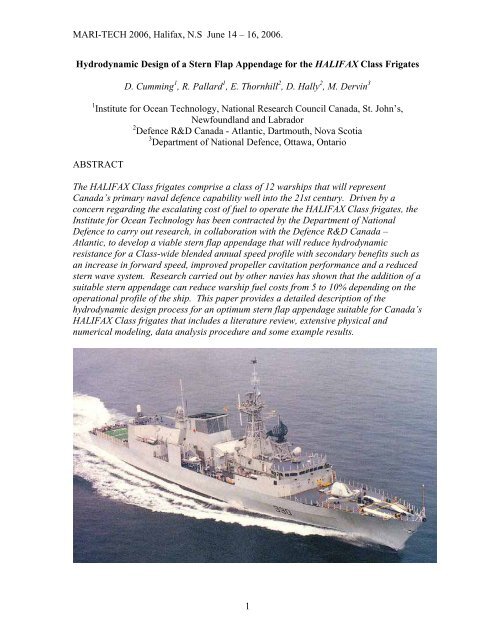
MARI-TECH 2006, Halifax, N.S June 14 – 16, 2006.<strong>Hydrodynamic</strong> <strong>Design</strong> <strong>of</strong> a <strong>Stern</strong> <strong>Flap</strong> <strong>Appendage</strong> <strong>for</strong> <strong>the</strong> <strong>HALIFAX</strong> Class FrigatesD. Cumming 1 , R. Pallard 1 , E. Thornhill 2 , D. Hally 2 , M. Dervin 31 Institute <strong>for</strong> Ocean Technology, National Research Council Canada, St. John’s,Newfoundland and Labrador2 Defence R&D Canada - Atlantic, Dartmouth, Nova Scotia3 Department <strong>of</strong> National Defence, Ottawa, OntarioABSTRACTThe <strong>HALIFAX</strong> Class frigates comprise a class <strong>of</strong> 12 warships that will representCanada’s primary naval defence capability well into <strong>the</strong> 21st century. Driven by aconcern regarding <strong>the</strong> escalating cost <strong>of</strong> fuel to operate <strong>the</strong> <strong>HALIFAX</strong> Class frigates, <strong>the</strong>Institute <strong>for</strong> Ocean Technology has been contracted by <strong>the</strong> Department <strong>of</strong> NationalDefence to carry out research, in collaboration with <strong>the</strong> Defence R&D Canada –Atlantic, to develop a viable stern flap appendage that will reduce hydrodynamicresistance <strong>for</strong> a Class-wide blended annual speed pr<strong>of</strong>ile with secondary benefits such asan increase in <strong>for</strong>ward speed, improved propeller cavitation per<strong>for</strong>mance and a reducedstern wave system. Research carried out by o<strong>the</strong>r navies has shown that <strong>the</strong> addition <strong>of</strong> asuitable stern appendage can reduce warship fuel costs from 5 to 10% depending on <strong>the</strong>operational pr<strong>of</strong>ile <strong>of</strong> <strong>the</strong> ship. This paper provides a detailed description <strong>of</strong> <strong>the</strong>hydrodynamic design process <strong>for</strong> an optimum stern flap appendage suitable <strong>for</strong> Canada’s<strong>HALIFAX</strong> Class frigates that includes a literature review, extensive physical andnumerical modeling, data analysis procedure and some example results.1
MARI-TECH 2006, Halifax, N.S June 14 – 16, 2006.1.0 INTRODUCTIONThis paper describes <strong>the</strong> hydrodynamic design ef<strong>for</strong>t to derive a suitable stern flap <strong>for</strong> <strong>the</strong><strong>HALIFAX</strong> Class frigates. The primary objective <strong>of</strong> this stern appendage is to reduce fuelconsumption without degrading o<strong>the</strong>r per<strong>for</strong>mance characteristics. The overall designprocess is delineated with a detailed description provided <strong>of</strong> <strong>the</strong> numerical predictionscarried out by Defence R & D Canada – Atlantic (DRDC Atlantic) based in Dartmouth,NS and bare hull resistance experiments carried out using a 1:13.54 scale (9.19 m long)physical model by <strong>the</strong> Institute <strong>for</strong> Ocean Technology in St. John’s, NL. Future ef<strong>for</strong>ts tovalidate <strong>the</strong> per<strong>for</strong>mance <strong>of</strong> <strong>the</strong> final flap design with fur<strong>the</strong>r numerical modelling,physical model experiments on a fully appended model, and full scale trials are included.2.0 BACKGROUNDAs multi-purpose plat<strong>for</strong>m, <strong>the</strong> <strong>HALIFAX</strong> Class frigates carry extensive anti-submarinewarfare and surface warfare weapons and sensors to complement its substantial anti-airwarfare defenses. The combination <strong>of</strong> its varied and proven weapon and sensor systemscoupled with modern damage control and machinery control systems makes this Classone <strong>of</strong> <strong>the</strong> most advanced warship designs in <strong>the</strong> world. The peace time role <strong>of</strong> <strong>the</strong>sevessels include a variety <strong>of</strong> important missions such as search and rescue, trainingdeployments, sovereignty patrols and combined operations with Canada’s allies.The <strong>HALIFAX</strong> Class frigates are fitted with twin inboard turning controllable pitchpropellers on exposed shafts supported by two sets <strong>of</strong> ‘A’ brackets. O<strong>the</strong>r appendagesinclude a large centerline rudder, a set <strong>of</strong> bilge keels and a centerline sonar dome fittednear <strong>the</strong> bow. The vessels are powered by one cruise diesel engine with <strong>the</strong> option to useone or two gas turbine engines <strong>for</strong> high speed operations. Fur<strong>the</strong>r in<strong>for</strong>mation on <strong>the</strong> fullscale ship including principal particulars, weapons and sensors as well as per<strong>for</strong>mancespecifications <strong>for</strong> <strong>the</strong> <strong>HALIFAX</strong> Class can be found in Reference 1.Starting in 2010, <strong>the</strong> twelve <strong>HALIFAX</strong> Class ships will undergo an extensive refitprogram; Frigate Life Extension (FELEX) that will enhance and extend <strong>the</strong> life <strong>of</strong> <strong>the</strong>seships up to at least 2025. With <strong>the</strong> anticipated rise in fuel costs over this time periodcombined with <strong>the</strong> positive results from research carried out on similar ships in o<strong>the</strong>rnavies (Reference 2), <strong>the</strong> Canadian Navy has initiated a project to explore <strong>the</strong> potential<strong>for</strong> reducing operating costs by fitting a effective stern appendage.According to in<strong>for</strong>mation provided in Reference 2, stern flaps improve fuel consumptionby modifying <strong>the</strong> pressure field under <strong>the</strong> hull afterbody, causing <strong>the</strong> flow to slow downover an area extending from <strong>the</strong> position <strong>of</strong> <strong>the</strong> flap to generally <strong>for</strong>ward <strong>of</strong> <strong>the</strong>propellers. Decreased flow velocity causes an increase in pressure, which in turn,reduces resistance due to reduced after-body suction <strong>for</strong>ce (<strong>for</strong>m drag).The overall project plan is described as follows:2
MARI-TECH 2006, Halifax, N.S June 14 – 16, 2006.1) Institute <strong>for</strong> Ocean Technology (IOT) staff were tasked to carry out a review <strong>of</strong>literature related to monohull stern appendage research and development(March/April 2005);2) Based on <strong>the</strong> results <strong>of</strong> <strong>the</strong> literature review, a recommendation wascommunicated to <strong>the</strong> Department <strong>of</strong> National Defence (DND) and DRDC Atlanticregarding <strong>the</strong> most promising stern appendage geometry;3) To reduce <strong>the</strong> scope <strong>of</strong> <strong>the</strong> physical modeling ef<strong>for</strong>t, DRDC Atlantic was taskedto carry out an investigation <strong>of</strong> several stern appendage geometries using variousnumerical prediction tools and provide recommendations to IOT with respect to<strong>the</strong> most likely optimum geometry <strong>for</strong> <strong>the</strong> <strong>HALIFAX</strong> Class;4) IOT was assigned responsibility <strong>for</strong> <strong>the</strong> design and fabrication <strong>of</strong> a 1:13.54 scale(9.19 m long) physical model <strong>of</strong> <strong>the</strong> <strong>HALIFAX</strong> Class frigate <strong>for</strong> <strong>the</strong> purpose <strong>of</strong>carrying out a matrix <strong>of</strong> bare hull resistance experiments using <strong>the</strong> IOT 200 mlong Towing Tank to identify <strong>the</strong> optimum stern appendage geometry <strong>for</strong> <strong>the</strong><strong>HALIFAX</strong> Class hull (testing completed January 2006);5) IOT were assigned responsibility <strong>for</strong> carrying out appended resistance, selfpropulsionand astern manoeuvring experiments on a fully appended physicalmodel <strong>of</strong> <strong>the</strong> <strong>HALIFAX</strong> Class frigate with final faired design <strong>of</strong> <strong>the</strong> optimum sternappendage in place to fur<strong>the</strong>r evaluate <strong>the</strong>ir influence on ship per<strong>for</strong>mance(planned <strong>for</strong> May – June 2006).6) IOT were also assigned responsibility to carry out a wake survey on <strong>the</strong> frigatehull <strong>for</strong>m with/without a final faired flap fitted to provide input data to DRDCAtlantic s<strong>of</strong>tware to predict flap impact on propeller cavitation inception speed(2006 – date TBD);7) Full scale trials may be carried out on a <strong>HALIFAX</strong> Class frigate fitted with aprototype stern flap appendage to evaluate propulsion, hydrodynamic noise andcavitation related issues (date TBD).Simplified sketches describing <strong>the</strong> options <strong>for</strong> stern appendages include a stern flap, sternwedge and integrated wedge-flap are depicted in Figure 1 from Reference 3.Figure 1: <strong>Stern</strong> <strong>Appendage</strong> OptionsDue to <strong>the</strong> proximity <strong>of</strong> <strong>the</strong> trailing edge <strong>of</strong> <strong>the</strong> large centerline rudder on <strong>the</strong> <strong>HALIFAX</strong>Class to <strong>the</strong> transom (Figure 2) however, <strong>the</strong> only viable option without expensivemodifications to <strong>the</strong> existing stern area was deemed to be a simple flap projecting from<strong>the</strong> edge <strong>of</strong> <strong>the</strong> transom.3
MARI-TECH 2006, Halifax, N.S June 14 – 16, 2006.Figure 2: Pr<strong>of</strong>ile Drawing/Dry Dock Photograph <strong>of</strong> Halifax Class Frigate <strong>Stern</strong>Thus <strong>the</strong> focus <strong>of</strong> <strong>the</strong> design ef<strong>for</strong>t was to isolate <strong>the</strong> optimum flap in terms <strong>of</strong> angle,chord length and span across <strong>the</strong> transom.3.0 NUMERICAL PREDICTION RESULTSTo reduce <strong>the</strong> scope <strong>of</strong> <strong>the</strong> physical modeling, DRDC Atlantic used a free surfacepotential flow program and a Reynolds-averaged Navier Stokes (RANS) solver toestimate <strong>the</strong> effectiveness <strong>of</strong> stern flap configurations in reducing <strong>the</strong> resistance. Fulldetails <strong>of</strong> <strong>the</strong>se calculations are given in References 4 to 6. <strong>Stern</strong> flaps with anglesbetween -5º and 20º (<strong>the</strong> angle is measured trailing edge downward from <strong>the</strong> horizontal),chord lengths between 0.5% and 2% <strong>of</strong> LBP, and spans from 0 to 9 metres were tested atspeeds between 10 and 30 knots. The resistance <strong>for</strong> each configuration was comparedwith <strong>the</strong> resistance <strong>for</strong> <strong>the</strong> hull with no flap fitted.Figure 3: Percent decrease in total resistance as a function <strong>of</strong> flap angle:speed = 20 knots; span = 9m.4
MARI-TECH 2006, Halifax, N.S June 14 – 16, 2006.As expected, <strong>for</strong> each speed, chord length and span, <strong>the</strong>re was an optimum angle at which<strong>the</strong> largest reduction <strong>of</strong> resistance was obtained (see Figure 3). Both potential flow andRANS calculations show that longer flaps are slightly better than shorter ones, but this is<strong>of</strong>fset by greater sensitivity to angle. In addition, it was expected that longer flaps wouldper<strong>for</strong>m worse at lower speeds when <strong>the</strong> transom was wet. The numerical models do nottreat this effect correctly. There<strong>for</strong>e it was suggested that lengths between 1% and 1.5%LBP should be tested on a physical model in <strong>the</strong> tank.Figure 4: Optimum flap angle as a function <strong>of</strong> speed: span = 9m.Figure 4 plots <strong>the</strong> optimum angle versus speed <strong>for</strong> flaps <strong>of</strong> different lengths as predictedby <strong>the</strong> potential flow program; in all cases <strong>the</strong> span is 9 metres. The optimum angleranges roughly between 5º and 9º <strong>for</strong> <strong>the</strong> two recommended chord lengths. The results<strong>for</strong> <strong>the</strong> RANS calculations were similar but predicted optimal angles that were severaldegrees higher. To cover <strong>the</strong> full range <strong>of</strong> optimum angles predicted by both methods, itwas recommended that angles between 5º and 12.5º be tested in <strong>the</strong> tank. The actual testprogram used angles between 4º and 13º in 3º degree increments.As expected, <strong>the</strong> tests in which <strong>the</strong> flap span was varied showed that <strong>the</strong> maximumbenefit could be obtained by making <strong>the</strong> span as wide as possible without incurringproblems in installation due to <strong>the</strong> turn <strong>of</strong> <strong>the</strong> bilge.4.0 DESCRIPTION OF BARE HULL RESISTANCE PHYSICAL MODEL TESTINGAn extensive bare hull resistance experimental program was carried out in <strong>the</strong> 200 m longIOT Towing Tank to evaluate a series <strong>of</strong> flap options with geometries based onrecommendations derived from <strong>the</strong> literature search and numerical studies:IOT Towing Tank Description: The IOT Towing Tank has dimensions <strong>of</strong> 200 m by 12 mby 7 m with a dual-flap wavemaker fitted at one end capable <strong>of</strong> generating uni-directionalregular waves up to 1 m in height or irregular waves up to a 0.5 m significant waveheight. A wave absorber consisting <strong>of</strong> a parabolic beach is fitted at <strong>the</strong> opposite end.Flexible side absorbers can also be deployed along <strong>the</strong> entire length <strong>of</strong> <strong>the</strong> tank tominimize <strong>the</strong> time between runs. The 80 t tow carriage capable <strong>of</strong> speeds up to 10 m/s is5
MARI-TECH 2006, Halifax, N.S June 14 – 16, 2006.used to accommodate models <strong>for</strong> a wide range <strong>of</strong> test types carried out in calm water orwaves.Description <strong>of</strong> Physical Model: The bare hull physical model (i.e.: no appendages)fabricated <strong>for</strong> this project was a 1:13.54 scale, 9.19 m long representation <strong>of</strong> <strong>the</strong><strong>HALIFAX</strong> Class frigate constructed using foam and glass rein<strong>for</strong>ced plastic - and paintedyellow as described in IOT model fabrication standard (Reference 7). Principalparticulars <strong>of</strong> ship and model tested at a full scale draft <strong>of</strong> 5.34 m level trim (modeldisplacement was scaled and corrected <strong>for</strong> fresh water) – <strong>the</strong> midpoint between post-FELEX Operational Light and end <strong>of</strong> life condition are provided as follows:ShipModelLength Between Perpendiculars LBP (m) 124.5 9.192Maximum Waterline Beam (m) 15.06 1.112Test Draft (m) 5.34 0.394Wetted Surface Area (m 2 ) 2073.16 11.30Displacement (tonnes Salt Water, kg Fresh Water) 5238.44 2056.7A photograph <strong>of</strong> <strong>the</strong> completed bare hull model is provided in Figure 5:Figure 5: 1:13.54 Scale <strong>HALIFAX</strong> Class Frigate ModelDescription <strong>of</strong> Instrumentation: Tow <strong>for</strong>ce was measured using a 250 lb S-type load cellwhile model sinkage, heel and trim were measured using <strong>the</strong> tow post mounted yo-yopotentiometer and gimbal Rotational Voltage Displacement Transducers (RVDT)respectively. Water temperature was periodically measured manually using a hand-helddigital <strong>the</strong>rmometer submerged at <strong>the</strong> nominal mean draft depth.Three NIKON D100 digital single lens reflex cameras were mounted on <strong>the</strong> tow carriageto take photographs <strong>of</strong> <strong>the</strong> steady state dynamic swell-up at <strong>the</strong> bow and stern as well as<strong>the</strong> wake during <strong>the</strong> steady state portion <strong>of</strong> each run.6
MARI-TECH 2006, Halifax, N.S June 14 – 16, 2006.All acquired analog DC signals were low pass filtered at 10 Hz, amplified as required anddigitized at 50 Hz using IOT’s standard data acquisition system and s<strong>of</strong>tware.Description <strong>of</strong> Test Program: With <strong>the</strong> model ballasted to <strong>the</strong> 5.34 m full scale level trimcondition, <strong>the</strong> full baseline resistance curve <strong>of</strong> <strong>the</strong> unappended model was evaluated asper <strong>the</strong> IOT standard resistance procedure (Reference 8) from 3.5 knots to 31.5 knots fullscale with several repeat runs included <strong>for</strong> data verification. The evaluation <strong>of</strong> eightflaps, two chord lengths (1% and 1.5% <strong>of</strong> LBP) and four angles ranging from 4 to 13degrees trailing edge down relative to <strong>the</strong> horizontal, was planned <strong>for</strong> <strong>the</strong> <strong>HALIFAX</strong> Classhull <strong>for</strong>m (see table below).<strong>Flap</strong> Angle (deg.) Chord (% LBP) Chord (m) – Full Scale<strong>Design</strong>ated L1A4 4 1 1.245<strong>Design</strong>ated L1A7 7 1 1.245<strong>Design</strong>ated L1A10 10 1 1.245<strong>Design</strong>ated L1A13 13 1 1.245<strong>Design</strong>ated L1P5A4 4 1.5 1.8675<strong>Design</strong>ated L1P5A7 7 1.5 1.8675<strong>Design</strong>ated L1P5A10 10 1.5 1.8675<strong>Design</strong>ated L1P5A13 13 1.5 1.8675NOTE: <strong>Flap</strong> angles trailing edge down – relative to horizontal.LBP = 124.5 m full scale.A sketch <strong>of</strong> a typical simplified flap with hard edges is provided in Figure 6:Figure 6: Sketch <strong>of</strong> Simplified <strong>Flap</strong>To optimize <strong>the</strong> available tank time, six point resistance experiments were carried out <strong>for</strong>each flap option in 5 knot increments from 5 to 30 knots full scale and initially comparedonline to a six point data set acquired <strong>for</strong> <strong>the</strong> unappended (no flap fitted) hull. Afteracquisition <strong>of</strong> <strong>the</strong> data <strong>for</strong> all <strong>the</strong> flap configurations, <strong>the</strong> six point curve <strong>for</strong> <strong>the</strong>unappended model was repeated <strong>for</strong> verification. The data set was <strong>the</strong>n reviewed and afull resistance curve acquired with <strong>the</strong> three most promising candidates <strong>for</strong> comparisonwith <strong>the</strong> full baseline curve. This test strategy was designed to acquire <strong>the</strong> necessary data7
MARI-TECH 2006, Halifax, N.S June 14 – 16, 2006.to determine <strong>the</strong> optimum flap <strong>for</strong> <strong>the</strong> existing <strong>HALIFAX</strong> Class frigates in an efficientmanner. Photographs <strong>of</strong> <strong>the</strong> model during testing are provided in Figure 7:Figure 7: Photographs <strong>of</strong> Model During TestingPreliminary Test Results: A preliminary review <strong>of</strong> <strong>the</strong> relative per<strong>for</strong>mance <strong>of</strong> each flapoption in comparison to <strong>the</strong> baseline unappended resistance data was evaluated using <strong>the</strong>data acquired during <strong>the</strong> abbreviated test program (6 point resistance curves) by plotting<strong>the</strong> Total Resistance Coefficient (C TM ) <strong>for</strong> <strong>the</strong> Model (appended)/ Total ResistanceCoefficient (C TM ) <strong>for</strong> <strong>the</strong> Model (unappended) vs. Froude Number where C TM wasdetermined using <strong>the</strong> following relationship:RTMCTM=20.5ρMSMVMR TM = total resistance <strong>for</strong> <strong>the</strong> model (N)ρ M = water density <strong>for</strong> <strong>the</strong> model test facility (kg/m 3 )S M = wetted surface area <strong>of</strong> <strong>the</strong> model (m 2 )V M = model speed (m/s)Based on <strong>the</strong> results <strong>of</strong> this evaluation, <strong>the</strong> following three most promising flaps wereinvestigated fur<strong>the</strong>r by carrying out full resistance curves:• 1% LBP chord length, 4 degree flap (L1A4)• 1% LBP chord length, 7 degree flap (L1A7)• 1.5% LBP chord length, 4 degree flap (L1P5A4)Detailed Data Analysis and Optimum <strong>Flap</strong> Selection: Typically, adding a flap to a hullincreases <strong>the</strong> resistance at lower speeds, at some point <strong>the</strong>re is a crossover whereby <strong>the</strong>reis a benefit at higher speeds. A typical plot <strong>of</strong> resistance induced by adding a flap relativeto an unappended hull is provided in Figure 8:8
MARI-TECH 2006, Halifax, N.S June 14 – 16, 2006.Tow Force Comparison Between Unappended Hull/<strong>Flap</strong> L1P5A4Tow Force Diff. (N)50-5 0 5 10 15 20 25 30 35-10-15-20-25-30Forward Speed (knots)<strong>Flap</strong> L1P5A4Figure 8: Relative Tow Force With/Without <strong>Flap</strong> FittedEffective power (P E ) was <strong>the</strong>n computed using both <strong>the</strong> ITTC’57 (Reference 9) as well asITTC’78 (Reference 10) methodologies. A spline curve was fitted to <strong>the</strong> effective powerdata and interpolated from zero to 30 knots in two knot increments. The criteria <strong>for</strong>evaluating a given stern appendage was computed single ship annual consumption <strong>of</strong> fuelbased on experimentally derived effective power using a Class-wide blended peace timepercent time at speed pr<strong>of</strong>ile (see Figure 9 below) <strong>for</strong> <strong>the</strong> <strong>HALIFAX</strong> Class hull <strong>for</strong>membedded in a DND Ship Endurance/Range Prediction EXCEL 1 spreadsheet (Reference11) that was tailored specifically <strong>for</strong> this project.Percent Time At Speed22201816141210864200.0 0.8 1.6 2.7 18.4 18.415.0 15.28.77.32.9 2.0 1.2 0.8 0.74.30 2 4 6 8 10 12 14 16 18 20 22 24 26 28 30Speed (knots)Figure 9: <strong>HALIFAX</strong> Class Frigate Peace Time Percent Time at Speed Pr<strong>of</strong>ile1 EXCEL (© Micros<strong>of</strong>t Corporation) spreadsheets were used <strong>for</strong> all <strong>the</strong> Ship Endurance/Range Predictionanalysis.9
MARI-TECH 2006, Halifax, N.S June 14 – 16, 2006.The single ship annual fuel consumption savings prediction based on <strong>the</strong> full resistancecurve data was approximately 1% as provided in Table 1 at <strong>the</strong> end <strong>of</strong> this paper.Predicted amount <strong>of</strong> fuel saved per year and percent fuel saving from baseline(unappended ship) is also included in Table 1.Conclusions & Recommendations: The trends observed in <strong>the</strong> IOT results acquired weregenerally similar to those reported in <strong>the</strong> open literature. Initially <strong>the</strong> addition <strong>of</strong> a flapincreased resistance, with a crossover at roughly 15 knots full scale with significantlyreduced fuel consumption provided <strong>for</strong> higher speeds. A minor reduction in bothdynamic sinkage and trim angle due to <strong>the</strong> addition <strong>of</strong> a flap was also noted.Bare hull resistance test data is assumed to be conservative since actual per<strong>for</strong>mance <strong>of</strong>full scale stern flaps have generally exceeded model scale predictions (Reference 2).Benefits provided by <strong>the</strong> stern flaps on <strong>the</strong> <strong>HALIFAX</strong> Class frigates are generally lowerthan reported in <strong>the</strong> literature <strong>for</strong> U.S. warships primarily due to <strong>the</strong> lower average speed<strong>of</strong> <strong>the</strong> peace time percent time at speed pr<strong>of</strong>ile.So in conclusion, eight flaps were investigated <strong>for</strong> <strong>the</strong> <strong>HALIFAX</strong> class hull <strong>for</strong>m - twochord lengths (1% and 1.5% LBP) and four trailing edge down angles ranging from 4 to13 degrees to <strong>the</strong> horizontal. Preliminary resistance results from <strong>the</strong> abbreviated (6 point)curves indicated only three <strong>of</strong> <strong>the</strong> flaps provided a benefit relative to <strong>the</strong> unappended hull.These three options were fur<strong>the</strong>r investigated with full resistance curves. Applying <strong>the</strong>computed results to <strong>the</strong> fuel prediction algorithm supplied by DND, both 4 degree flaps(1% and 1.5% <strong>of</strong> LBP) provide a similar overall benefit with <strong>the</strong> longer chord length flapbeing slightly superior. A sketch <strong>of</strong> <strong>the</strong> final optimum flap with rounded edges to befabricated <strong>for</strong> fur<strong>the</strong>r validation tests is provided in Figure 10:Figure 10: Final <strong>Flap</strong> <strong>Design</strong> <strong>for</strong> <strong>the</strong> Physical Model5.0 ADDITIONAL FLAP VALIDATION EFFORT PLANNEDThe following ef<strong>for</strong>t is planned to fur<strong>the</strong>r evaluate <strong>the</strong> final flap design:10
MARI-TECH 2006, Halifax, N.S June 14 – 16, 2006.1) Appended Resistance Experiments: Resistance experiments on <strong>the</strong> fully appendedmodel over a <strong>for</strong>ward speed range from 3.5 to 31.5 knots full scale with/withoutfinal flap in place ballasted to <strong>the</strong> 5.34 m level trim condition.2) Self-Propulsion Experiments: Self-propulsion experiments at 6, 10, 14, 18, 22, 28knots and full speed with <strong>the</strong> fully appended model fitted with/without <strong>the</strong> finalflap design. IOT has recently procured <strong>the</strong> equipment necessary to propel thisvery large model at 30 knots full scale (4.193 m/s model scale) along withdynamometers to measure <strong>the</strong> propulsion parameters (shaft speed, torque andthrust). Stock 5-bladed warship propellers are available to propel <strong>the</strong> model.3) Astern Manoeuvring: Astern manoeuvring will consist <strong>of</strong> steady speed asternruns from 1 to 15 knots full scale as well as crash stops using speed pr<strong>of</strong>ilesderived from actual full scale trials. All experiments will be carried outwith/without final flap design and dedicated instrumentation will be used assess<strong>the</strong> structural loads on <strong>the</strong> flap. Crash stop runs will include:- 10 knots ahead full scale to full astern- 20 knots ahead full scale to full astern- high speed ahead to stop- high speed ahead to full astern4) Wake Survey: wake survey to be carried out specifically to acquire data <strong>for</strong> inputto dedicated DRDC Atlantic s<strong>of</strong>tware designed to evaluate any change inpropeller cavitation inception speed due to <strong>the</strong> presence <strong>of</strong> <strong>the</strong> final flap.5) Full Scale Trials: Full scale trials are in <strong>the</strong> very early planning stage but couldinclude some or all <strong>of</strong> <strong>the</strong> following trials be<strong>for</strong>e and after any flap is fitted: calmwater propulsion, manoeuvring including standard turning circles, zig zags, steadystate astern test and crash stops, seakeeping, propeller viewing and hydrodynamicnoise evaluation on a sound range. Presumably <strong>the</strong> final flap as fitted to <strong>the</strong><strong>HALIFAX</strong> Class would look similar to <strong>the</strong> flap installed on <strong>the</strong> USS CurtusWilbur (DDG 54) shown in Figure 11 from Reference 2.An investigation is also planned with a 2 m transom extension option. For thisconfiguration, a preliminary investigation has shown an improvement in resistance <strong>of</strong>greater than 4% over <strong>the</strong> existing hull.11
MARI-TECH 2006, Halifax, N.S June 14 – 16, 2006.Figure 11: <strong>Stern</strong> <strong>Flap</strong> Installed on <strong>the</strong> USS Curtus Wilbur (DDG 54)6.0 SECONDARY BENEFITS OF STERN FLAPSIf a flap was fitted to <strong>the</strong> <strong>HALIFAX</strong> Class frigate hull <strong>for</strong>m, <strong>the</strong> full scale influence shouldcon<strong>for</strong>m to those listed in <strong>the</strong> open literature (Reference 12) including:• Delivered power reductions a few percent greater than <strong>the</strong> resistance reductiondue to improved propulsive efficiency;• Reduced propeller loading;• Reduced vibration and noise;• Increased cavitation inception speed;• A reduction in both near field and far field wave energy;• A slight increase in maximum <strong>for</strong>ward speed; and generally positive impacts interms <strong>of</strong> emissions from ship internal combustion engines.Thus over <strong>the</strong> next few years, assuming <strong>the</strong> required funding is secured, <strong>the</strong> CanadianNavy should start deriving <strong>the</strong> many benefits from installation <strong>of</strong> stern flaps to thiscritical naval asset.7.0 ACKNOWLEDGEMENTSFunding <strong>for</strong> this project was provided by DND. The authors would like to thank all IOTtechnical staff that assisted with this project.8.0 REFERENCES1) Su<strong>the</strong>rland, Capt. (N) R.A., Dumbrille, Cdr. L.P., Stenson, Cdr. M.A., “The CanadianPatrol Frigate: Today’s Technology”, Proc. <strong>of</strong> <strong>the</strong> ASNE Symposium: Destroyer,Cruiser and Frigate Technology, Biloxi & Pascagoula, Mississippi, October 2 – 4,1986, pp. 197-249.2) Cusanelli, D.S., Karafiath, G.,”Advances in <strong>Stern</strong> <strong>Flap</strong> <strong>Design</strong> and Application”, 6 thInternational Conference on Fast Sea Transportation (FAST’01), September 4 – 6,2001, Southampton, U.K.3) Cusanelli, D.S., Percival, S.,”CFD Development and Model Test Evaluation on anIntegrated Wedge-<strong>Flap</strong> <strong>for</strong> <strong>the</strong> DDG 79 Flight IIA”, NSWCCD-50-TR—2001/024,September 2001.4) Thornhill, E., Hally, D, ”CFD Analysis <strong>of</strong> <strong>Stern</strong> <strong>Flap</strong> Configurations <strong>for</strong> <strong>the</strong> CanadianPatrol Frigate”, DRDC Atlantic TR 2005-219, Defence R&D Canada – Atlantic,2005. LIMITED DISTRIBUTION12
MARI-TECH 2006, Halifax, N.S June 14 – 16, 2006.5) Hally, D, ”Potential Flow Calculations <strong>of</strong> <strong>the</strong> Effect <strong>of</strong> <strong>Stern</strong> <strong>Flap</strong>s and Wedges on <strong>the</strong>Canadian Patrol Frigate”, DRDC Atlantic TR 2005-220, Defence R&D Canada –Atlantic, 2005. LIMITED DISTRIBUTION6) Thornhill, E., ”CFD Calculations <strong>of</strong> <strong>the</strong> Effect <strong>of</strong> <strong>Stern</strong> <strong>Flap</strong>s and Wedges on <strong>the</strong>Canadian Patrol Frigate”, DRDC Atlantic TR 2005-254, Defence R&D Canada –Atlantic, 2005. LIMITED DISTRIBUTION7) “Construction <strong>of</strong> Models <strong>of</strong> Ships, Offshore Structures, and Propellers”, IOT StandardTest Method GM-1, V9.0, October 28, 2004.8) “Resistance in Open Water”, IOT Standard Test Method TM-1, V6.0, April 2, 2004.9) Proceedings <strong>of</strong> 8 th International Towing Tank Conference (ITTC), Madrid, Spain,1957.10) ITTC Recommended Procedure 7.5-02-03-01.4, “1978 International Towing TankConference (ITTC) Per<strong>for</strong>mance Prediction Method”, 1999.11) Dervin, M.F.,”Ship Endurance / Range Prediction”, DND Reference #D-03-002-010/SG-001, (EXCEL Workbook), 2005.12) Cusanelli, D.S.,”<strong>Stern</strong> <strong>Flap</strong>s – A Chronicle <strong>of</strong> Success at Sea (1989-2002)”,Innovations in Marine Transportation, SNAME Nor<strong>the</strong>rn Cali<strong>for</strong>nia Section JointSection Meeting, Pacific Grove, Cali<strong>for</strong>nia, May 30 – June 2, 2002.13
MARI-TECH 2006, Halifax, N.S June 14 – 16, 2006.ITTC'78ITTC'57RES1F L1A4F L1A7F L1P5A4F RES1F L1A4F L1A7F L1P5A4FBaselineEnter Time At Sea Per Year Days 100 100 100 100 100 100 100 100FO Available For PM Tonnes 386.09 385.48 386.13 385.23 385.45 384.87 385.54 384.63Endurance Range N. Miles 3745.26 3768.38 3743.82 3777.77 3769.17 3791.11 3766.08 3800.48Time Between Refuelings Days 10.52 10.58 10.52 10.61 10.59 10.65 10.58 10.68No. Of Refuelings per ''100'' Days9.51 9.45 9.51 9.42 9.45 9.39 9.45 9.37Annual Fuel Consumption Tonnes 3670.05 3641.75 3671.83 3630.36 3640.79 3614.27 3644.55 3603.03FUEL SAVED/YEAR (tonnes) 28.29 -1.78 39.69 26.52 -3.75 37.76% FUEL SAVING FROM BASELINE 0.77% -0.05% 1.08% 0.73% -0.10% 1.04%Table 1: Predicted Annual Fuel Consumption <strong>for</strong> Three Optimum <strong>Flap</strong>sPeace Time Percent Time at Speed Pr<strong>of</strong>ile14