C Sta rt - Müller Elektronik
C Sta rt - Müller Elektronik
C Sta rt - Müller Elektronik

You also want an ePaper? Increase the reach of your titles
YUMPU automatically turns print PDFs into web optimized ePapers that Google loves.
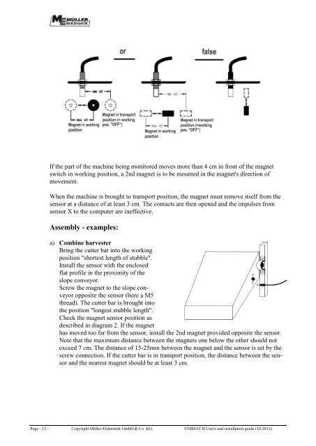
If the pa<strong>rt</strong> of the machine being monitored moves more than 4 cm in front of the magnet<br />
switch in working position, a 2nd magnet is to be mounted in the magnet's direction of<br />
movement.<br />
When the machine is brought to transpo<strong>rt</strong> position, the magnet must remove itself from the<br />
sensor at a distance of at least 3 cm. The contacts are then opened and the impulses from<br />
sensor X to the computer are ineffective.<br />
Assembly - examples:<br />
a) Combine harvester<br />
Bring the cutter bar into the working<br />
position "sho<strong>rt</strong>est length of stubble".<br />
Install the sensor with the enclosed<br />
flat profile in the proximity of the<br />
slope conveyor.<br />
Screw the magnet to the slope conveyor<br />
opposite the sensor (bore a M5<br />
thread). The cutter bar is brought into<br />
the position "longest stubble length".<br />
Check the magnet sensor position as<br />
described in diagram 2. If the magnet<br />
has moved too far from the sensor, install the 2nd magnet provided opposite the sensor.<br />
Note that the maximum distance between the magnets one below the other should not<br />
exceed 7 cm. The distance of 15-25mm between the magnet and the sensor is set by the<br />
screw connection. If the cutter bar is in transpo<strong>rt</strong> position, the distance between the sensor<br />
and the nearest magnet should be at least 3 cm.<br />
Page - 12 - Copyright <strong>Müller</strong>-<strong>Elektronik</strong> GmbH & Co. KG, UNIMAT II User's and installation guide (10.2012)