C Sta rt - Müller Elektronik
C Sta rt - Müller Elektronik
C Sta rt - Müller Elektronik

Create successful ePaper yourself
Turn your PDF publications into a flip-book with our unique Google optimized e-Paper software.
3 EC declaration of conformity<br />
This product has been manufactured in conformity with the following national and harmonised<br />
standards as specified in the current EMC Directive 89/336/EC:<br />
• EN ISO 14982<br />
4 Installation instructions<br />
4.1 Computer<br />
Operating voltage is 12 V and must be taken directly from the battery or from the 12-volt<br />
sta<strong>rt</strong>er. Care should be taken when laying the battery cable and it should be sho<strong>rt</strong>ened if<br />
necessary. The crimpon ring terminal for the ground line (blue) and the end sleeve for<br />
strands for the + line (brown) should be fitted using suitable pliers. The end sleeve for<br />
strands for the + line are in the connection clamp of the fuse holder.<br />
brown = + 12 volts<br />
blue = ground<br />
!<br />
4.2 Sensors - generally<br />
Attention !!!<br />
The voltage supply must be taken directly from the battery or from the<br />
12-v sta<strong>rt</strong>er. Attention must be paid to polarity.<br />
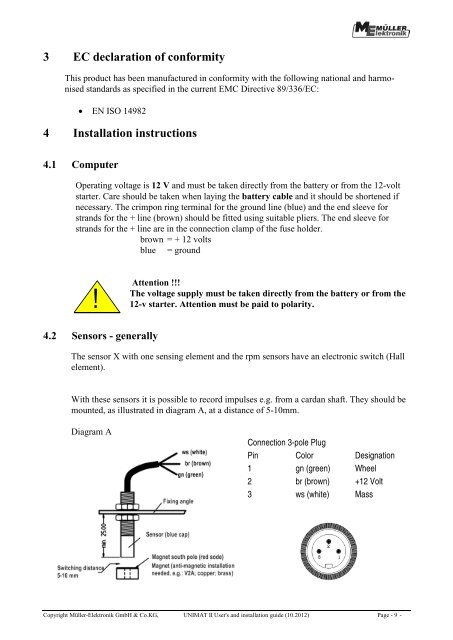
The sensor X with one sensing element and the rpm sensors have an electronic switch (Hall<br />
element).<br />
With these sensors it is possible to record impulses e.g. from a cardan shaft. They should be<br />
mounted, as illustrated in diagram A, at a distance of 5-10mm.<br />
Diagram A<br />
Connection 3-pole Plug<br />
Pin Color Designation<br />
1 gn (green) Wheel<br />
2 br (brown) +12 Volt<br />
3 ws (white) Mass<br />
Copyright <strong>Müller</strong>-<strong>Elektronik</strong> GmbH & Co.KG, UNIMAT II User's and installation guide (10.2012) Page - 9 -