
Create successful ePaper yourself
Turn your PDF publications into a flip-book with our unique Google optimized e-Paper software.
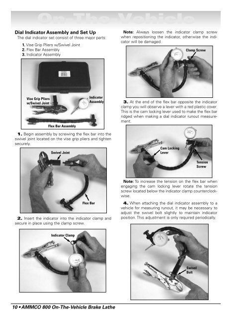
<strong>On</strong>-<strong>The</strong>-<strong>Vehicle</strong>Dial Indicator Assembly and Set Up<strong>The</strong> dial indicator set consist of three major parts:1. Vise Grip Pliers w/Swivel Joint2. Flex Bar Assembly3. Indicator AssemblyNote: Always loosen the indicator clamp screwwhen repositioning the indicator, otherwise the indicatorwill be damaged.Clamp ScrewVise Grip Pliersw/Swivel JointFlex Bar AssemblyIndicatorAssembly3. At the end of the flex bar opposite the indicatorclamp you will observe a lever with a red plastic cover.This is the cam locking lever used to make the flex barridged when making a dial indicator runout measurement.1. Begin assembly by screwing the flex bar into theswivel joint located on the vise grip pliers and tightensecurely.Swivel JointCam LockingLeverTensionScrewFlex Bar2. Insert the indicator into the indicator clamp andsecure in place using the clamp screw.Note: To increase the tension on the flex bar whenengaging the cam locking lever rotate the tensionscrew located below the indicator clamp counterclockwise.4. When attaching the dial indicator assembly to avehicle for measuring runout, it may be necessary toadjust the swivel bolt slightly to maintain indicatorposition. This adjustment is only required periodically.Indicator ClampSwivelBolt10 • AMMCO 800 <strong>On</strong>-<strong>The</strong>-<strong>Vehicle</strong> Brake Lathe