Designing a USB Keyboard and PS/2® Mouse Combination Device ...
Designing a USB Keyboard and PS/2® Mouse Combination Device ...
Designing a USB Keyboard and PS/2® Mouse Combination Device ...

Create successful ePaper yourself
Turn your PDF publications into a flip-book with our unique Google optimized e-Paper software.
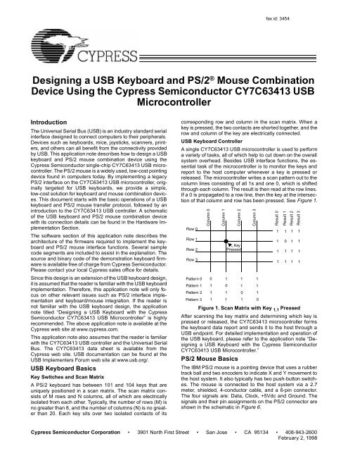
fax id: 3454<strong>Designing</strong> a <strong>USB</strong> <strong>Keyboard</strong> <strong>and</strong> <strong>PS</strong>/2 ® <strong>Mouse</strong> <strong>Combination</strong><strong>Device</strong> Using the Cypress Semiconductor CY7C63413 <strong>USB</strong>MicrocontrollerIntroductionThe Universal Serial Bus (<strong>USB</strong>) is an industry st<strong>and</strong>ard serialinterface designed to connect computers to their peripherals.<strong>Device</strong>s such as keyboards, mice, joysticks, scanners, printers,<strong>and</strong> others can all benefit from the connectivity providedby <strong>USB</strong>. This application note describes how to design a <strong>USB</strong>keyboard <strong>and</strong> <strong>PS</strong>/2 mouse combination device using theCypress Semiconductor single-chip CY7C63413 <strong>USB</strong> microcontroller.The <strong>PS</strong>/2 mouse is a widely used, low-cost pointingdevice found in computers today. By implementing a legacy<strong>PS</strong>/2 interface on the CY7C63413 <strong>USB</strong> microcontroller, originallytargeted for <strong>USB</strong> keyboards, we provide a simple,low-cost solution for keyboard <strong>and</strong> mouse combination devices.This document starts with the basic operations of a <strong>USB</strong>keyboard <strong>and</strong> <strong>PS</strong>/2 mouse transfer protocol, followed by anintroduction to the CY7C63413 <strong>USB</strong> controller. A schematicof the <strong>USB</strong> keyboard <strong>and</strong> <strong>PS</strong>/2 mouse combination devicewith its connection details can be found in the Hardware ImplementationSection.The software section of this application note describes thearchitecture of the firmware required to implement the keyboard<strong>and</strong> <strong>PS</strong>/2 mouse interface functions. Several samplecode segments are included to assist in the explanation. Thesource <strong>and</strong> binary code of the demonstration keyboard firmwareis available free of charge from Cypress Semiconductor.Please contact your local Cypress sales office for details.Since this design is an extension of the <strong>USB</strong> keyboard design,it is assumed that the reader is familiar with the <strong>USB</strong> keyboardimplementation. Therefore, this application note will only focuson other relevant issues such as <strong>PS</strong>/2 interface implementation<strong>and</strong> keyboard/mouse integration. If the reader isnot familiar with the <strong>USB</strong> keyboard design, the applicationnote titled “<strong>Designing</strong> a <strong>USB</strong> <strong>Keyboard</strong> with the CypressSemiconductor CY7C63413 <strong>USB</strong> Microcontroller” is highlyrecommended. The above application note is available at theCypress web site at www.cypress.com.This application note also assumes that the reader is familiarwith the CY7C63413 <strong>USB</strong> controller <strong>and</strong> the Universal SerialBus. The CY7C63413 data sheet is available from theCypress web site. <strong>USB</strong> documentation can be found at the<strong>USB</strong> Implementers Forum web site at www.usb.org/.<strong>USB</strong> <strong>Keyboard</strong> BasicsKey Switches <strong>and</strong> Scan MatrixA <strong>PS</strong>/2 keyboard has between 101 <strong>and</strong> 104 keys that areuniquely positioned in a scan matrix. The scan matrix consistsof M rows <strong>and</strong> N columns, all of which are electricallyisolated from each other. Typically, the number of rows (M) isno greater than 8, <strong>and</strong> the number of columns (N) is no greaterthan 20. Each key sits over two isolated contacts of itscorresponding row <strong>and</strong> column in the scan matrix. When akey is pressed, the two contacts are shorted together, <strong>and</strong> therow <strong>and</strong> column of the key are electrically connected.<strong>USB</strong> <strong>Keyboard</strong> ControllerA single CY7C63413 <strong>USB</strong> microcontroller is used to performa variety of tasks, all of which help to cut down on the overallsystem overhead. Besides <strong>USB</strong> interface functions, the essentialtask of the microcontroller is to monitor the keys <strong>and</strong>report to the host computer whenever a key is pressed orreleased. The microcontroller writes a scan pattern out to thecolumn lines consisting of all 1s <strong>and</strong> one 0, which is shiftedthrough each column. The result is then read at the row lines.If a 0 is propagated to a row line, then the key at the intersectionof that column <strong>and</strong> row has been pressed. See Figure 1.Row 0Row 1Row 2Row 3Pattern 0Pattern 1Pattern 2Pattern 3Column 0Column 10 11 01 11 1Column 2KeyPressedFigure 1. Scan Matrix with Key 1,1 PressedAfter scanning the key matrix <strong>and</strong> determining which key ispressed or released, the CY7C63413 microcontroller formsthe keyboard data report <strong>and</strong> sends it to the host through a<strong>USB</strong> endpoint. For detailed implementation <strong>and</strong> operation ofthe <strong>USB</strong> keyboard, please refer to the application note “<strong>Designing</strong>a <strong>USB</strong> <strong>Keyboard</strong> with the Cypress SemiconductorCY7C63413 <strong>USB</strong> Microcontroller.”<strong>PS</strong>/2 <strong>Mouse</strong> BasicsThe IBM <strong>PS</strong>/2 mouse is a pointing device that uses a rubbertrack ball <strong>and</strong> two encoders to indicate X <strong>and</strong> Y movement tothe host system. It also typically has two push-button switches.The mouse is connected to the host system via a 2.7meter, shielded, 4-conductor cable, <strong>and</strong> a 6-pin connector.The four signals are: Data, Clock, +5Vdc <strong>and</strong> Ground. Thesignals <strong>and</strong> their pin assignments on the <strong>PS</strong>/2 connector areshown in the schematic in Figure 6.Column 31 11 10 11 0Result 0Result 1Result 2Result 31111101111111111Cypress Semiconductor Corporation • 3901 North First Street • San Jose • CA 95134 • 408-943-2600February 2, 1998
<strong>Designing</strong> a <strong>USB</strong> <strong>Keyboard</strong> <strong>and</strong> <strong>PS</strong>/2 <strong>Mouse</strong> <strong>Combination</strong> <strong>Device</strong>Operation ModesThe <strong>PS</strong>/2 mouse can operate in four different modes, shownbelow:• Reset Mode: in this mode a self-test is initiated duringpower-on or by a Reset comm<strong>and</strong>. Upon successful completionof the self-test, a completion code (AAh) <strong>and</strong> an IDcode (00h) are transmitted to the host system. Any comm<strong>and</strong>ssent before the transmission of the completion code<strong>and</strong> the ID byte are ignored. If the self-test fails, the mouseresponds with a error code (FCh) <strong>and</strong> an ID code (00h),after which the mouse is disabled <strong>and</strong> awaits further comm<strong>and</strong>sfrom the host system.• Stream Mode: in this mode a data report is only transmittedto the host system if a button is pressed or released orif at least one count of movement has been detected. Themaximum rate of transfer is the programmed sample rate.• Remote Mode: also known as “polling” mode. In this mode,a data report is transmitted only in response to a Read Datacomm<strong>and</strong>.• Wrap Mode: in this mode, any byte of data sent by the hostsystem, except hexadecimal values ECh <strong>and</strong> FFh, is returnedby the mouse.<strong>PS</strong>/2 <strong>Mouse</strong> Protocol <strong>and</strong> Comm<strong>and</strong>sThe <strong>PS</strong>/2 mouse communicates with the host system througha defined protocol consisting of comm<strong>and</strong>s <strong>and</strong> responses.The ACK byte (FAh) is always the first response to any validinput received from the host system, except for Resend comm<strong>and</strong><strong>and</strong> in Wrap mode. Table 1 shows a list of all the validcomm<strong>and</strong>s.Table 1. <strong>PS</strong>/2 <strong>Mouse</strong> Comm<strong>and</strong>sHex CodeFFFEF6F5F4F3F2F0EEECEBEAE9E8Comm<strong>and</strong>ResetResendSet DefaultDisableEnableSet Sampling RateRead <strong>Device</strong> TypeSet Remote ModeSet Wrap ModeReset Wrap ModeRead DataSet Stream ModeStatus RequestSet ResolutionE7 Set Scaling 2:1E6Reset ScalingOnly the mouse comm<strong>and</strong>s that are used in this design arediscussed below. For complete description of the <strong>PS</strong>/2 mousecomm<strong>and</strong>s <strong>and</strong> operation, please see “IBM Personal System/2<strong>Mouse</strong> Technical Reference.” from IBM (DocumentNumber S68X-2229-00).The following are the comm<strong>and</strong>s used by this design <strong>and</strong> theirbrief descriptions:• Reset: this comm<strong>and</strong> causes the mouse to enter the resetmode <strong>and</strong> do an internal self-test.• Resend: any time the mouse receives an invalid comm<strong>and</strong>,it returns a Resend comm<strong>and</strong> to the host system. The hostsystem, in turn, sends this comm<strong>and</strong> when it detects anyerror in any transmission from the mouse. When the mousereceives a Resend comm<strong>and</strong>, it retransmits the last packetof data sent.• Set Stream Mode: this comm<strong>and</strong> sets the Stream mode.• Enable: this comm<strong>and</strong> is used in the Stream mode to begintransmission.• Disable: this comm<strong>and</strong> is used in the Stream mode to stoptransmissions initiated by the mouse. The mouse respondsto all other comm<strong>and</strong>s while disabled. If the mouse is inthe Stream mode, it must be disabled before sending it anycomm<strong>and</strong> that requires a response.• Read Data: this comm<strong>and</strong> requests that all data definedin the data packet format be transmitted. This comm<strong>and</strong> isexecuted in either remote or stream mode. The data istransmitted even if there has been no movement since thelast report or the switch status is unchanged.<strong>Mouse</strong> Data ReportIn the Stream mode, a data report is sent at the end of asample interval if there has been a button event or mousemovement. The sampling rate is, by default, 100 reports persecond, but it can be changed by the Set Sampling Rate comm<strong>and</strong>.On the other h<strong>and</strong>, in the Remote (or polling) mode, adata report is sent in response to a Read Data comm<strong>and</strong>.The data report is three bytes long <strong>and</strong> its format is shown inTable 2.Table 2. <strong>PS</strong>/2 <strong>Mouse</strong> Data Report FormatByte Bit Description1 7 Y Data Overflow 1= Overflow6 X Data Overflow 1= Overflow5 Y Data Sign 1= Negative4 X Data Sign 1= Negative3 Reserved2 Reserved1 Right Button Status 1= Pressed0 Left Button Status 1 = Pressed2 7–0 X Data3 7–0 Y DataData TransmissionData transmission between the <strong>PS</strong>/2 mouse <strong>and</strong> the host systemis carried out by 2 signals: Clock <strong>and</strong> Data. The Clocksignal is used to clock serial data. The mouse generates theclocking signal when sending data to or receiving data fromthe host system. The host system requests the mouse to receivehost data output by forcing the Data line LOW <strong>and</strong> allowingClock to go HIGH. Figure 2 illustrates a <strong>PS</strong>/2 dataframe containing a single byte of data.2
<strong>Designing</strong> a <strong>USB</strong> <strong>Keyboard</strong> <strong>and</strong> <strong>PS</strong>/2 <strong>Mouse</strong> <strong>Combination</strong> <strong>Device</strong>Start Bit (Always = 0)Stop Bit (Always = 1)DataBit 0DataBit 1. . . . Data OddBit 7 ParityFigure 2. <strong>PS</strong>/2 Data Frame FormatCommunication is bidirectional using the Clock <strong>and</strong> Data signallines. The signal for each of these lines comes from opencollector devices, allowing either the mouse or the host systemto drive a line LOW. During a non-transmission state, bothClock <strong>and</strong> Data lines are held HIGH. For detailed informationon signaling protocol for data transmission using Clock <strong>and</strong>Data lines, please refer to “IBM Personal System/2 <strong>Mouse</strong>Technical Reference.”Introduction to CY7C63413The CY7C63413 is a high performance 8-bit RISC microcontrollerwith an integrated <strong>USB</strong> Serial Interface Engine (SIE).The architecture implements 37 instructions that are optimizedfor <strong>USB</strong> applications. The CY7C63413 has a built-inclock oscillator <strong>and</strong> timers, as well as general purpose I/Olines that can be configured as inputs with internal pull-ups,open-drain outputs, or traditional CMOS outputs. High performance,low-cost human-interface type computer peripheralssuch as a keypad or keyboard can be implemented with aminimum of external components <strong>and</strong> firmware effort.Clock CircuitThe CY7C63413 has a built-in clock oscillator <strong>and</strong> PLL-basedfrequency doubler. This circuit allows a cost-effective 6-MHzceramic resonator to be used externally while the on-chipRISC core runs at 12 MHz.<strong>USB</strong> Serial Interface Engine (SIE)The operation of the SIE is totally transparent to the user. Inthe receive mode, <strong>USB</strong> packet decode <strong>and</strong> data transfer tothe endpoint FIFO are automatically done by the SIE. The SIEthen generates an interrupt to invoke a service routine after apacket is unpacked.In the transmit mode, data transfer from the endpoint <strong>and</strong> theassembly of the <strong>USB</strong> packet are h<strong>and</strong>led automatically by theSIE.General Purpose I/OThe CY7C63413 has 32 general purpose I/O lines dividedinto 4 ports: Port 0 through Port 3. One such I/O circuit isshown in Figure 3. Each port (8 bits) can be configured asinputs with internal pull-ups (7 Kohms), open drain outputs(high-impedance inputs), or traditional CMOS outputs. Theport configuration is determined according to Table 3 below.Table 3. GPIO ConfigurationPortConfigurationBitsPinInterrupt Bit Driver modeInterruptPolarity11 X Resistive –10 0 CMOS disabledOutput10 1 CMOS Input disabled01 X Open Drain –00 X Open Drain +GPIOCFGmode2-bitsV CCInternalData BusInterruptEnableInternalBufferDataOutLatchPort WritePort ReadControl ControlQ17 KΩQ2to InterruptControllerQ3ESDGPIOPinFigure 3. One General Purpose I/O Line3
<strong>Designing</strong> a <strong>USB</strong> <strong>Keyboard</strong> <strong>and</strong> <strong>PS</strong>/2 <strong>Mouse</strong> <strong>Combination</strong> <strong>Device</strong>Ports 0 to 2 offer low current drive with a typical current sinkcapability of 7 mA. Port 3 offers a higher current drive, with atypical current sink of 12 mA which can be used to drive LEDs.Each General Purpose I/O (GPIO) is capable of generatingan interrupt to the RISC core. Interrupt polarity is selectableon a per port basis using the GPIO Configuration Register(see Table 3 above.) Selecting a negative polarity (“–”) willcause falling edges to trigger an interrupt, while a positivepolarity (“+”) selects rising edges as triggers. The interrupttriggered by a GPIO line is individually enabled by a dedicatedbit in the Interrupt Enable Register. All GPIO interrupts arefurther masked by the Global GPIO Interrupt Enable Bit in theGlobal Interrupt Enable Register.The GPIO Configuration Register is located at I/O address0x08. The Data Registers are located at I/O addresses 0x00to 0x03 for Port 0 to Port 3 respectively.Power-up ModeThe CY7C63413 offers 2 modes of operation after a power-on-reset(POR) event: suspend-on-reset (typical for a <strong>USB</strong>application) <strong>and</strong> run-on-reset (typical for a non-<strong>USB</strong> application).The suspend-on-reset mode is selected by attaching apull-up resistor (100 to 470 KΩ) to V CC on Bit 7 of GPIO Port3. The run-on-reset mode is selected by attaching a pull-downresistor (0 to 470 KΩ) to ground on Bit 7 of GPIO Port 3. SeeFigure 4. As the <strong>USB</strong> keyboard <strong>and</strong> <strong>PS</strong>/2 mouse combinationdevice is a <strong>USB</strong> implementation, the CY7C63413 should beconfigured for suspend-on-reset.Port 2 is configured as resistive inputs (7 Kohm pull-ups toV CC ), <strong>and</strong> are connected to the M rows of the scan matrix (upto 8 rows are supported). Ports 0, 1, <strong>and</strong> 3 are configured asopen drain outputs, <strong>and</strong> are used to connect to the N columnsof the scan matrix, the 3 LEDs (Num Lock, Caps Lock, <strong>and</strong>Scroll Lock), <strong>and</strong> the two <strong>PS</strong>/2 mouse signals. Since the <strong>PS</strong>/2signals occupy two bits of Port 3, we can only support keyboardscan matrices up to 18 columns. Most of the existingAT-101 or AT-104 type keyboards do not use more than 18columns. For keyboards that use scan matrices with morethan 18 columns, it is usually possible to relocate the keysfrom the columns 19 <strong>and</strong> greater to unassigned locations oncolumns 18 or below. The three LEDs are connected to thelower three bits of Port 3 as well (for high current drive). Forscan matrices with less then 8 rows or 18 columns, the unusedport bits should be left unconnected.The <strong>PS</strong>/2 signals are connected to the <strong>PS</strong>/2 mouse througha 6-pin <strong>PS</strong>/2 receptacle. +5V <strong>and</strong> GND are also available onthe receptacle to power the <strong>PS</strong>/2 mouse. The strap optionpull-up resistor R8 (470 KΩ) selects the Suspend-On-Resetmode for the <strong>USB</strong> microcontroller, <strong>and</strong> the series terminationresistor R7 (100Ω) is used to reduce crosstalk problems overthe <strong>PS</strong>/2 lines.During a keyboard scan test where no key is pressed, the rowport data bits will be HIGH since all row lines are internallypulled up to V CC . When a key is pressed, driving its columnport line LOW (key scan pattern) will cause its row line to goLOW as well. See Figure 5.VCCPort 3, Bit 7Rpullup100 100K to to 470 470K KΩOHMFigure 4. (a) Suspend-On-Reset ModeRow Port LineRow iColumn jColumn Port LinePort 3, Bit 7Closed when key i,j is pressedDriven LOW by the key scanRpulldown0 to 470K OHMFigure 4. (b) Run-On-Reset ModeHardware ImplementationFigure 6 is the schematic for a <strong>USB</strong> keyboard <strong>and</strong> <strong>PS</strong>/2mouse combination device. This schematic is very similar tothe one in the <strong>USB</strong> keyboard-only design. The major differenceis the addition of the <strong>PS</strong>/2 mouse Clock <strong>and</strong> Data signallines to the GPIO Port 3 bit 6 <strong>and</strong> bit 7, respectively.Figure 5. Row/Column Port ConfigurationA 6 MHz ceramic resonator is connected to the clock inputsof the microcontroller. This component should be placed asclose to the microcontroller as possible.According to the <strong>USB</strong> specification, the <strong>USB</strong> D– line of alow-speed device (1.5 Mbps) should be tied to a voltagesource between 3.0V <strong>and</strong> 3.6V with a 1.5 KΩ pull-up terminator.The CY7C63413 eliminates the need for a 3.3V regulatorby specifying a 7.5-KΩ resistor connected between the <strong>USB</strong>D– line <strong>and</strong> the nominal 5V V CC . This is compliant with “<strong>Device</strong>Working Group Review Request 135.”4
<strong>Designing</strong> a <strong>USB</strong> <strong>Keyboard</strong> <strong>and</strong> <strong>PS</strong>/2 <strong>Mouse</strong> <strong>Combination</strong> <strong>Device</strong>Figure 6. Hardware Implementation - Schematic5
<strong>Designing</strong> a <strong>USB</strong> <strong>Keyboard</strong> <strong>and</strong> <strong>PS</strong>/2 <strong>Mouse</strong> <strong>Combination</strong> <strong>Device</strong>Firmware Implementation<strong>USB</strong> InterfaceLike the <strong>USB</strong> keyboard-only device, the <strong>USB</strong> keyboard <strong>and</strong><strong>PS</strong>/2 mouse combination device is also a <strong>USB</strong> Human Interface<strong>Device</strong> (HID). All <strong>USB</strong> HID-class devices follow the same<strong>USB</strong> start-up procedure. The procedure is shown in Figure 7.<strong>Device</strong> Plug-in(Power On Reset)Bus ResetEnumerationData Acquisition/TransferFigure 7. <strong>USB</strong> Start-Up ProcedureHowever, designing a <strong>USB</strong> HID combination device (keyboard<strong>and</strong> mouse functions) requires different approaches inphases such as <strong>USB</strong> enumeration <strong>and</strong> data acquisition/transfer.We will discuss these differences in the following sections.<strong>Device</strong> Plug-in <strong>and</strong> Bus Reset phases remain basically thesame for the combination device as for the keyboard-only design.EnumerationA combination device follows the same usual <strong>USB</strong> enumerationprocess, where the device responds to the host with anumber of <strong>USB</strong> descriptors. In this design, the combinationdevice chooses to transmit both the keyboard <strong>and</strong> mousedata reports through a single interface, <strong>and</strong> over the sameinterrupt endpoint (endpoint 1). This means that the HID reportdescriptor needs to be modified to describe both the keyboard<strong>and</strong> mouse data reports. All the other <strong>USB</strong> descriptors(device, configuration, interface, class, <strong>and</strong> endpoint descriptors)can remain the same as in the keyboard-only design.HID Report DescriptorThe HID report descriptor is basically divided into two applicationcollections, corresponding to the keyboard <strong>and</strong> themouse collections. To allow the host system to distinguishdifferent reports arriving over the same interrupt endpoint, aReport ID tag is added to each of the two reports. The ReportID value indicates the prefix added to a particular report. Forexample, the report descriptor defines a 3-byte mouse reportwith a report ID of 02. Therefore, whenever the combinationdevice needs to send a mouse report in response to an INpacket on endpoint 1, it will generate a 4-byte data report, inwhich the first byte is the report ID 02. The keyboard report isassigned a report ID of 01.Example of HID Report DescriptorUsage Page (Generic Desktop)Usage (<strong>Keyboard</strong>)Collection (Application)ReportID (0x01)Usage Page (Key Codes)Usage Minimum (234)Usage Maximum (231)Logical Minimum (0)Logical Maximum (1)Report Size (1)Report Count (8)Input (Data,Variable,Absolute)Report Count (1)Report Size (8)Input (Constant);reserved byteReport Count (5);LED reportReport Size (1)Usage Page (LEDs)Usage Minimum (1)Usage Maximum (5)Output (Data,Variable,Absolute)Report Count (1)Report Size (3)Output (Constant);3-bit paddingReport Count (6)Report Size (8)Logical Minimum (0)Logical Maximum (101)Usage Page (Key Codes)Usage Minimum (0)Usage Maximum (101)Input (Data, Array);key array(6)End CollectionUsage Page (Generic Desktop)Usage (<strong>Mouse</strong>)Collection (Application)ReportID (0x02)Usage (Pointer)Collection (Linked)Usage Page (Buttons)Usage Minimum (1)Usage Maximum (3)Logical Minimum (0)Logical Maximum (1)Report Count (3);three buttonsReport Size (1)Input (Data,Variable,Absolute)Report Count (1)Report Size (5)Input (Constant);5-bit paddingUsage Page (Generic Desktop)Usage (X)Usage (Y)Logical Minimum (-127)Logical Maximum (127)Report Size (8);X <strong>and</strong> Y dataReport Count (2)Input (Data,Variable,Variable)End CollectionEnd Collection6
<strong>Designing</strong> a <strong>USB</strong> <strong>Keyboard</strong> <strong>and</strong> <strong>PS</strong>/2 <strong>Mouse</strong> <strong>Combination</strong> <strong>Device</strong>A more detailed description of HID <strong>and</strong> all the items used inan HID report descriptor can be found in the “<strong>Device</strong> ClassDefinition for Human Interface <strong>Device</strong>s (HID) Revision 1.0.”Data Acquisition/TransferThe firmware alternately scans the keyboard scan matrix <strong>and</strong>polls the <strong>PS</strong>/2 mouse to determine whether data reports needto be sent to the host system. As mentioned earlier, both thekeyboard <strong>and</strong> mouse data reports are sent to the host usingendpoint 1. When the firmware determines there is a key ormany keys pressed, it sets up the keyboard data report, loadsit into the endpoint 1 FIFO, <strong>and</strong> enables the endpoint 1 transmission.Then the keyboard data report will be sent when thenext IN packet is received on the endpoint 1 from the host.The <strong>PS</strong>/2 mouse follows the same steps to send its data reportto the host.The HID keyboard data report is 8 bytes long, <strong>and</strong> consists ofone byte of modifiers plus 7 key scan code bytes. Table 4shows the format of the keyboard report. Usage codes foreach key can be found in Appendix A.3 of the “<strong>Device</strong> ClassDefinition for Human Interface <strong>Device</strong>s (HID).”Since the maximum data packet size of an interrupt pipe fora low-speed <strong>USB</strong> device is limited to 8 bytes, the deviceneeds to send the complete report (1-byte report ID plus8-byte data report) in two interrupt transactions, instead ofonly one in the keyboard-only design. In the first interrupttransaction, a report ID <strong>and</strong> the first 7 bytes of the data reportare sent in response to a IN token. In the second transaction,a report ID <strong>and</strong> the last byte of the data report are sent inresponse to the following IN token.When any LED keys (i.e., Num Lock, Caps Lock, Scroll Lock)are pressed or released, the host system issues a SETUPpacket with a Set_Report request through the control pipe toEnd Point 0, followed by an OUT packet with 2 data bytes. Thefirst byte corresponds to the report ID <strong>and</strong> the second byteindicates which LED should be on or off (see Table 5.)Table 4. <strong>USB</strong> <strong>Keyboard</strong> Data Report FormatByte b7 b6 b5 b4 b3 b2 b1 b00ModifiersRightGUIRightAlt1 Reserved2 Key 1 scan code3 key 2 scan code4 Key 3 scan code5 Key 4 scan code6 Key 5 scan code7 Key 6 scan codeRightShiftRightCtrlLeftGUILeftAltLeftShiftLeftCtrlTable 5. <strong>USB</strong> <strong>Keyboard</strong> Set_Report Data Format for LEDByte b7 b6 b5 b4 b3 b2 b1 b00LEDReportThe HID mouse data report is 3 bytes long (see Table 6). Thefirmware polls the <strong>PS</strong>/2 mouse <strong>and</strong> obtains the <strong>PS</strong>/2 mousedata packet (see Table 2). Then it extracts the button <strong>and</strong> X,Y movement information from the <strong>PS</strong>/2 data packet to composethe HID mouse data report. Different from the keyboardreport, the complete mouse report can be sent in a single<strong>USB</strong> interrupt transaction since it is only 4 bytes long (1 byteof report ID <strong>and</strong> 3 bytes of mouse data).The byte order <strong>and</strong> bit field positions for both the keyboard<strong>and</strong> mouse reports are consistent with the Boot Protocol requirementsfor legacy systems.<strong>PS</strong>/2 InterfaceState Machine ImplementationKanaConstantConstantConstantComposeTable 6. <strong>USB</strong> <strong>Mouse</strong> Data Report FormatScrollLockCapsLockByte b7 b6 b5 b4 b3 b2 b1 b00 Padding LeftAlt1 Horizontal (X) Displacement2 Vertical (Y) DisplacementLeftShiftNumLockLeftButtonThe <strong>USB</strong> keyboard <strong>and</strong> <strong>PS</strong>/2 mouse combination device firmwareis an extension of the keyboard-only firmware, with theaddition of <strong>PS</strong>/2 interface code <strong>and</strong> changes to allow functionalintegration. The <strong>PS</strong>/2 interface code consists of a numberof subroutines which can be called by the main code to perform<strong>PS</strong>/2 related tasks. In this application note, we will mainlydiscuss the principle of operation <strong>and</strong> how to utilize thesesubroutines to operate a <strong>PS</strong>/2 mouse. For implementationdetails of the subroutines, please refer to the firmware sourcecode.The <strong>PS</strong>/2 mouse interface code is implemented by two statemachines: mouse_int <strong>and</strong> mouse_machine. The former operatesat the bit/byte transaction level <strong>and</strong> the latter operates atthe byte/comm<strong>and</strong> transaction level. The mouse_int statemachine manages the transmission <strong>and</strong> reception of databytes over the <strong>PS</strong>/2 bus. Since the <strong>PS</strong>/2 mouse always drivesthe clock signal connected to a GPIO pin, the mouse_int statemachine is driven by GPIO interrupts generated from the fallingedge of the <strong>PS</strong>/2 clock. In the GPIO interrupt service routine,the microcontroller will either read from or write to the<strong>PS</strong>/2 data line, depending on whether it is receiving data fromor sending data to the <strong>PS</strong>/2 mouse.The states of mouse_int corresponds to bit states of a <strong>PS</strong>/2byte transmission or reception (i.e., start bit, data bits, parity<strong>and</strong> stop bit). The mouse_int is initiated either by a byte transmissionrequest from the high-level state machine,mouse_machine, or by the start of a new receive byte fromthe mouse. Upon completion of a byte transfer (normal orotherwise) by mouse_int, the <strong>PS</strong>/2 bus is inhibited (by holding7
<strong>Designing</strong> a <strong>USB</strong> <strong>Keyboard</strong> <strong>and</strong> <strong>PS</strong>/2 <strong>Mouse</strong> <strong>Combination</strong> <strong>Device</strong>the clock line LOW) to allow the high-level state machine,mouse_machine, to act.The high-level state machine (mouse_machine) is, in turn,driven by periodic calls from the application (the keyboard <strong>and</strong><strong>PS</strong>/2 mouse firmware in this case). Whenever we initiate amouse comm<strong>and</strong>, mouse_machine must be called regularlyfrom the application in order to process its state sequences.Making these regular calls to mouse_machine is referred toas “operating” the mouse_machine. Every call tomouse_machine returns an idle/busy indication in the microcontroller’sC-bit (carry). It returns C-bit = 0 if it is idle (i.e., nomouse comm<strong>and</strong>s are currently in process), <strong>and</strong> C-bit = 1 ifa mouse comm<strong>and</strong> is currently being processed. No newmouse comm<strong>and</strong> should be initiated by the application unlessmouse_machine is idle. Further, mouse_machine can only bemade busy by a comm<strong>and</strong> initiated by the application or apower-up reset.A sample code in Figure 8 shows how to initiate a mousecomm<strong>and</strong> <strong>and</strong> “operate” mouse_machine. Call to mouse_pollinitiates the Read Data comm<strong>and</strong> to the mouse, <strong>and</strong> sets themouse_machine to the corresponding state. The subsequentloop calls mouse_machine to sequence through the statesuntil the C-bit = 0, indicating the state machine is done <strong>and</strong>idle.<strong>Mouse</strong>Task:call mouse_poll ;send poll cmdtw3:call mouse_machine ;wait until donejc tw3 ;jump back if C= 1Figure 8. Operating mouse_machine<strong>PS</strong>/2 Support SubroutinesA number of support subroutines are provided to facilitate theoperation of the <strong>PS</strong>/2 mouse. The main firmware code callsthese subroutines to initialize, set operation mode <strong>and</strong> readdata from the <strong>PS</strong>/2 mouse. Their descriptions <strong>and</strong> usages areas follows:• ps2_init: this subroutine initializes the <strong>PS</strong>/2 mouse port. Itmust be called from the main code within 500 ms of power-up,before the <strong>PS</strong>/2 mouse starts transmitting. Upon applicationof power <strong>and</strong> completion of its self-diagnostics,the mouse will automatically transmit a two-byte initializationpattern (0xAA <strong>and</strong> 0x00). Regular calls tomouse_machine must be made after the call to ps2_inituntil it returns idle, indicating the transmission of the initializationpattern is complete. The receipt of the pattern recognizesthat the mouse is attached to the device.• mouse_reset: this subroutine initiates a Reset comm<strong>and</strong>to the mouse, causing it to execute its self-diagnostics <strong>and</strong>return the initialization pattern. After a call to mouse_reset,mouse_machine must be operated until it returns idle. Inthis instance, the returned data from a properly functioningmouse will be a three-byte string (0xFA, 0xAA, <strong>and</strong> 0x00).The first byte is the ACK byte to the Reset comm<strong>and</strong>, <strong>and</strong>the next two bytes are the initialization pattern. Note thatthe initialization pattern will only be transmitted automaticallyby the mouse at power-up. Therefore, if the <strong>USB</strong> microcontrollergets reset by some reason, it is recommendedthat mouse_reset be called to duplicate the reset/initializationsequence, in order to make sure that the firmwarerecognizes the mouse is attached.• ps2_status(): this subroutine can be called oncemouse_machine goes idle after the reset/initialization sequenceto determine if a mouse is attached. It returns “0’in the accumulator (register A) if no mouse is attached;otherwise, “1” is returned.• mouse_init: Once the mouse has gone through the reset/initializationphase <strong>and</strong> is detected as a result,mouse_init must be invoked by the main code to preparethe mouse for data polling. This is done by sending the SetRemote Mode <strong>and</strong> Enable comm<strong>and</strong>s to the mouse.<strong>Mouse</strong>_init operates the mouse_machine through thecomm<strong>and</strong> sending transactions, <strong>and</strong> only returns when themouse is properly configured. <strong>Mouse</strong>_init is also used toreinitialize the mouse upon leaving the suspend mode.Suspend/resume <strong>and</strong> remote wakeup issues will be discussedin the next section.• mouse_poll: Upon successful completion of mouse_init,data may be polled from the mouse by calling themouse_poll subroutine. Note that mouse_poll merely initiatesthe transaction, which is then driven to completionby operating mouse_machine until it returns idle. When thetransaction is completed, the 3-byte <strong>PS</strong>/2 mouse data reportwill be available in RAM area at addressmouse_packetV.• mouse_suspend: this subroutine is called before the microcontrollerenters suspend state. It initiates a Set StreamMode comm<strong>and</strong> <strong>and</strong> operates mouse_machine until thetransaction is complete.<strong>Keyboard</strong> <strong>and</strong> <strong>Mouse</strong> Firmware IntegrationMain LoopThe main loop of the firmware (Figure 9) runs two tasks continuously:ScanTask <strong>and</strong> <strong>Mouse</strong>Task. The ScanTask is thesame keyboard task in the keyboard-only firmware. It scansthe keyboard scan matrix to determine any key statuschange, loads the keyboard report to endpoint 1 FIFO <strong>and</strong>Main LoopScanTask<strong>Mouse</strong>Task20 ms DelayFigure 9. Main Loop8
<strong>Designing</strong> a <strong>USB</strong> <strong>Keyboard</strong> <strong>and</strong> <strong>PS</strong>/2 <strong>Mouse</strong> <strong>Combination</strong> <strong>Device</strong>sends it to the host system if necessary. For more details onits operation please see the <strong>USB</strong> keyboard application note.Similarly, the <strong>Mouse</strong>Task calls mouse_poll subroutine to readdata from the <strong>PS</strong>/2 mouse, copies the mouse report frommemory buffer to endpoint 1 FIFO <strong>and</strong> transmits it to the hostsystem. An arbitrary delay of 20 ms was added before thecode loops back. This is to make sure that the <strong>PS</strong>/2 mousegets ready to respond to the next polling comm<strong>and</strong>.<strong>USB</strong> Suspend/Resume <strong>and</strong> Remote WakeupAccording to the <strong>USB</strong> Specification 1.0, a device has to gointo suspend mode after 3 ms of no bus activity. The 1 ms ISRdetermines when this condition occurs (by reading the BusActivity bit, bit 3, of the <strong>USB</strong> Status <strong>and</strong> Control Register, 1Fh)<strong>and</strong> suspends the microcontroller. This is accomplished bysetting bit 0 (Run bit) <strong>and</strong> bit 3 (Suspend bit) of the ProcessorStatus <strong>and</strong> Control Register (FFh). The microcontroller willresume operation upon one of the following three events:<strong>USB</strong> bus activity, keyboard activity, or <strong>PS</strong>/2 mouse activity.<strong>USB</strong> bus activity resume is carried out automatically by themicrocontroller. On the other h<strong>and</strong>, keyboard <strong>and</strong> <strong>PS</strong>/2mouse activity during suspend are detected through GPIOinterrupts. For this reason, before entering suspend, GPIOinterrupts for the keyboard <strong>and</strong> mouse must be properly enabled.For the keyboard, prior to suspending the microcontroller, the1 ms ISR pulls down all the column port lines <strong>and</strong> enable afalling edge interrupt on all Port 2 lines (Row port). If any keyis pressed while in suspended state, one of the row lines willbe pulled LOW <strong>and</strong> trigger a GPIO interrupt. The GPIO ISRwill then send a resume signal (force a K state where D+ isHIGH <strong>and</strong> D– is LOW for 10 ms) to wake up the host system(remote wake up).The <strong>PS</strong>/2 mouse normally operates in Remote (polling)mode, where the mouse only transmits a data report in responseto a Read Data comm<strong>and</strong>. When the microcontrollerenters suspend state, however, it no longer polls the mousefor data. Thus, it is desirable to allow the mouse to be capableof autonomously waking up the microcontroller if it has datato transmit (mouse movement or button press). This is accomplishedby placing the mouse in Stream mode before enteringsuspend. In the Stream mode, the <strong>PS</strong>/2 mouse willtransmit data at regular intervals any time it has new dataavailable, generating GPIO interrupts <strong>and</strong> waking up the microcontroller.Before entering suspend the main code must call functionmouse_suspend, which initiates a Set Stream Mode comm<strong>and</strong><strong>and</strong> operates mouse_machine until the transaction iscomplete. Then the main code will enable suspend, leavingthe Port 3 GPIO interrupt enabled. During suspend state, anyactivity on the <strong>PS</strong>/2 port will cause an entry to the GPIO ISR,which will immediately inhibit the mouse transmission. Duringthe wakeup sequence, the firmware must also call mouse_initto place the mouse back to Remote mode for normal datapolling operations.GPIO Interrupt Service RoutineIn the keyboard-only firmware, the GPIO ISR was only usedto h<strong>and</strong>le the keyboard resume <strong>and</strong> the sending of the remotewakeup signal after leaving the suspend state. For the keyboard<strong>and</strong> mouse combination device, however, the GPIO interruptis also used to drive the <strong>PS</strong>/2 low-level state machine(mouse_int) at each falling edge of the <strong>PS</strong>/2 clock signal.NoBus StillIdle?YesSend RemoteWakeup SignalGPIO ISRIn SuspendMode?ReturnYesCall <strong>Mouse</strong>Bit/byte LevelState Machinemouse_intFigure 10. GPIO Interrupt Service RoutineUpon entering the GPIO ISR (See Figure 10), a test is doneto determine whether the firmware is running in normal operationmode or has just left suspend mode. If it is in normaloperation, the mouse_int state machine is called; otherwise,the remote wakeup sequence begins.1-ms Interrupt Service RoutineFor the keyboard <strong>and</strong> mouse combination firmware, a fewchanges were added to the keyboard-only 1 ms ISR (Figure11):• The keyboard scan task is no longer scheduled every 4 msas in the keyboard-only firmware.• Before entering suspend state, the <strong>PS</strong>/2 mouse is placedin Stream mode. Also, after coming out of suspend, themouse is set back to Remote mode.• The <strong>PS</strong>/2 mouse time-out counter increment <strong>and</strong> check isincluded. If the <strong>PS</strong>/2 is in the active state for more than 25ms <strong>and</strong> no transfer happens, a time-out condition will occur,resetting the <strong>PS</strong>/2 bus <strong>and</strong> setting the state machines toidle.<strong>PS</strong>/2 Signal Timing IssueFor reliable <strong>PS</strong>/2 bus operation, the GPIO interrupt serviceprovided by the main code must ensure that the latency betweena falling edge on the <strong>PS</strong>/2 clock line <strong>and</strong> resultant entryinto the bit/byte level state machine (mouse_int) is no morethan 17 µs. This requirement precludes the disabling of interruptsfor long periods of time by other code modules, whilemouse_machine is busy. Special attention should be given tothe 1 ms ISR or other ISRs that may disable interrupt for longperiods of time.No9
<strong>Designing</strong> a <strong>USB</strong> <strong>Keyboard</strong> <strong>and</strong> <strong>PS</strong>/2 <strong>Combination</strong> <strong>Device</strong>ConclusionThe two main enabling factors of the proliferation of the <strong>USB</strong>devices are cost <strong>and</strong> functionality. The CY7C63413 meetsboth requirements by integrating the <strong>USB</strong> SIE <strong>and</strong> multi-functionI/Os with a <strong>USB</strong> optimized RISC core in a low-cost part.In this application note, the CY7C63413 <strong>USB</strong> microcontrolleris used to implement a <strong>USB</strong> keyboard <strong>and</strong> <strong>PS</strong>/2 mouse combinationdevice. The <strong>PS</strong>/2 interface, fully implemented in firmware,preserves the use of a legacy <strong>PS</strong>/2 mouse without anyadditional cost.1 ms ISRClear Watchdog Timer3 ms ofbus inactivity?NoYesSave GPIO PortSettingsWrite ‘0’ to <strong>Keyboard</strong>Column Port BitsEnable GPIO Interrupton Port 2 <strong>and</strong> 3Set the <strong>PS</strong>/2 <strong>Mouse</strong>to Stream ModeGo SuspendRESUMERestore GPIO PortSettingsDisable GPIO Interrupton Port 2Has 12 mspast?Yes<strong>Keyboard</strong> DebounceFIFO incrementNoRestore <strong>PS</strong>/2 <strong>Mouse</strong>to Remote Mode<strong>PS</strong>/2 <strong>Mouse</strong>Timeout CheckReturnFigure 11. 1 ms Interrupt Service Routine<strong>PS</strong>/2 is a registered trademark of the International Business Machines Corp.© Cypress Semiconductor Corporation, 1998. The information contained herein is subject to change without notice. Cypress Semiconductor Corporation assumes no responsibility for the useof any circuitry other than circuitry embodied in a Cypress Semiconductor product. Nor does it convey or imply any license under patent or other rights. Cypress Semiconductor does not authorizeits products for use as critical components in life-support systems where a malfunction or failure may reasonably be expected to result in significant injury to the user. The inclusion of CypressSemiconductor products in life-support systems application implies that the manufacturer assumes all risk of such use <strong>and</strong> in doing so indemnifies Cypress Semiconductor against all charges.