Designing a Universal Serial Bus (USB) Device Using the Cypress ...
Designing a Universal Serial Bus (USB) Device Using the Cypress ...
Designing a Universal Serial Bus (USB) Device Using the Cypress ...

Create successful ePaper yourself
Turn your PDF publications into a flip-book with our unique Google optimized e-Paper software.
<strong>Designing</strong> a<br />
<strong>Universal</strong> <strong>Serial</strong> <strong>Bus</strong> (<strong>USB</strong>) <strong>Device</strong><br />
<strong>Using</strong> <strong>the</strong> <strong>Cypress</strong> CY7C63001<br />
A <strong>USB</strong> Thermometer
<strong>Cypress</strong> <strong>USB</strong> Thermometer Application Note<br />
Introduction<br />
Purpose<br />
The purpose of this application note is to:<br />
• Provide a brief overview of <strong>the</strong> <strong>Universal</strong> <strong>Serial</strong> <strong>Bus</strong> (<strong>USB</strong>) system.<br />
• Describe <strong>the</strong> design of an actual <strong>USB</strong> device using a CY7C63001 <strong>Cypress</strong> <strong>USB</strong> controller<br />
device.<br />
• Illustrate how a Windows application communicates with a <strong>USB</strong> device through <strong>the</strong> Windows<br />
drivers.<br />
It provides:<br />
• A set of common assembly language routines for use by <strong>Cypress</strong> <strong>USB</strong> controllers to handle<br />
<strong>the</strong> interface to <strong>the</strong> <strong>USB</strong> system.<br />
• A <strong>USB</strong> design guide for designing with <strong>the</strong> <strong>Cypress</strong> <strong>USB</strong> controller.<br />
• A device driver which may be used to develop applications for non HID <strong>USB</strong> devices.<br />
• Examples of communicating with drivers and <strong>USB</strong> devices for applications software.<br />
• A glossary of common <strong>USB</strong> terms with which a user may be unfamiliar. We have defined<br />
highlighted terms in <strong>the</strong> glossary.<br />
Scope<br />
It is assumed that <strong>the</strong> reader is familiar with (but not necessarily expert at) Windows programming<br />
using Microsoft Visual Basic (or C) and with assembly level programming of micro controllers.<br />
This application note covers <strong>the</strong> basics of <strong>the</strong> <strong>USB</strong> bus architecture, but it is not intended to be a<br />
comprehensive reference to <strong>the</strong> <strong>USB</strong>. For more information on <strong>USB</strong>, please see “The <strong>Universal</strong><br />
<strong>Serial</strong> <strong>Bus</strong> Specification.” This document is available online for download (http://www.usb.org)<br />
and it is included in <strong>the</strong> <strong>USB</strong> Starter Kit CD-ROM.<br />
It is beyond <strong>the</strong> scope of this application note to address any issues involving <strong>the</strong> actual writing of<br />
Windows device drivers.<br />
Operating Systems and Hardware Requirements for <strong>USB</strong> Support<br />
There are several requirements that must be met in order to successfully use <strong>USB</strong> devices on<br />
your system:<br />
• Your hardware must support <strong>the</strong> <strong>USB</strong>.<br />
Your system must contain a <strong>USB</strong> host controller and have <strong>USB</strong> connectors.<br />
• Your BIOS must enable <strong>the</strong> <strong>USB</strong> host controller or provide <strong>the</strong> option to enable <strong>USB</strong>.<br />
• Your operating system must support <strong>the</strong> <strong>USB</strong>.<br />
• You must have <strong>the</strong> proper drivers for your <strong>USB</strong> device.<br />
<strong>Cypress</strong> Semiconductor Ver 1.03<br />
Page 1
<strong>Cypress</strong> <strong>USB</strong> Thermometer Application Note<br />
Hardware<br />
• Integrated mo<strong>the</strong>rboard support<br />
Most mo<strong>the</strong>rboards and systems produced today include integrated support for <strong>the</strong> <strong>USB</strong>. If<br />
your system does not have integrated support, you can use an add-in adapter (see below).<br />
<strong>USB</strong> connectors are identified by <strong>the</strong> symbol:<br />
• BIOS support<br />
If your mo<strong>the</strong>rboard has integrated support for <strong>the</strong> <strong>USB</strong>, your mo<strong>the</strong>rboard must also have a<br />
BIOS that has support for <strong>the</strong> integrated hardware. Also, <strong>the</strong> BIOS Setup must enable <strong>the</strong><br />
integrated <strong>USB</strong> hardware. Currently, some systems have <strong>USB</strong> ports and hardware, but do<br />
not have BIOS support for <strong>the</strong> ports (odd, but true).<br />
If you are having problems getting your system to recognize your integrated <strong>USB</strong> Host Hub,<br />
you should check both to see if your BIOS has support for <strong>the</strong> <strong>USB</strong> Host Hub and to ensure<br />
that <strong>the</strong> host hub is enabled. The control of <strong>the</strong> <strong>USB</strong> hardware should show up as an<br />
“Enable/Disable” item in your BIOS setup program.<br />
• Add-in adapter support<br />
If your mo<strong>the</strong>rboard does not support <strong>the</strong> <strong>USB</strong> directly or you wish to add additional hubs to<br />
your system, adapters can be added to an existing computer to provide support. Usually,<br />
<strong>the</strong>se adapters plug into <strong>the</strong> PCI bus.<br />
Operating Systems<br />
At <strong>the</strong> time of this writing, <strong>the</strong>re is only one released operating system that supports <strong>the</strong> <strong>USB</strong> and<br />
that is <strong>the</strong> Microsoft OSR 2.1 release of Windows95. Microsoft OSR2.1 is an upgrade of<br />
Microsoft OSR2.0. OSR2.0 does not support <strong>USB</strong> and must be upgraded to OSR2.1 with <strong>the</strong><br />
appropriate upgrade from Microsoft.<br />
Currently OSR2.0 and OSR2.1 are only available from OEM’s on newly purchased machines or<br />
on <strong>the</strong> Microsoft Developer’s Network CD’s. They are not available through retail channels.<br />
There is currently no upgrade for Microsoft Windows 95 that provides <strong>USB</strong> support.<br />
There is also currently no upgrade for Microsoft Windows NT that provides <strong>USB</strong> support.<br />
Full support is available in Windows 98 and Windows NT5.0. These operating systems are<br />
expected to be generally released in 1998. Developers may obtain beta copies of Windows 98 for<br />
early development. To get more information about <strong>the</strong> Beta Developers Program, go to <strong>the</strong><br />
Microsoft web site (http://www.microsoft.com).<br />
Drivers<br />
The vendor of <strong>the</strong> <strong>USB</strong> device will supply drivers that may be required for your device.<br />
<strong>Cypress</strong> Semiconductor Ver 1.03<br />
Page 2
<strong>Cypress</strong> <strong>USB</strong> Thermometer Application Note<br />
Common Questions<br />
Q. “How do I determine if my operating system supports <strong>the</strong> <strong>USB</strong>”<br />
A. In order to use <strong>the</strong> <strong>USB</strong> with <strong>the</strong> Windows operating system, you need to have OSR2.1<br />
or a more recent version of Windows such as Memphis (Windows98, currently in Beta<br />
test).<br />
You may determine <strong>the</strong> version of Windows you have through <strong>the</strong> System Properties.<br />
Information to help you determine which version of <strong>the</strong> Windows operating system you<br />
have is also available from Microsoft at:<br />
http://www.microsoft.com/kb/articles/q158/2/38.htm<br />
Identifying your operating system as OSR2.0, OSR2.1 or Memphis:<br />
ORS 2.0 is Windows 95 version 4.00.950b.<br />
OSR 2.1 is Windows 95 version 4.00.950b with <strong>the</strong> <strong>USB</strong> supplement installed.<br />
Memphis is Windows 98 version 4.10.1423 or later.<br />
System Properties<br />
The version of Windows you have installed can be found by clicking on <strong>the</strong> "System" icon<br />
in <strong>the</strong> Control Panel (See Figure 1 and Figure 2).<br />
Figure 1<br />
Microsoft Windows 95 TM Control Panel<br />
<strong>Cypress</strong> Semiconductor Ver 1.03<br />
Page 3
<strong>Cypress</strong> <strong>USB</strong> Thermometer Application Note<br />
Windows Version<br />
Figure 2<br />
Windows System Properties<br />
You can determine whe<strong>the</strong>r <strong>the</strong> <strong>USB</strong> supplement has been installed by using <strong>the</strong><br />
“Add/Remove Programs” application which is also found on <strong>the</strong> control panel. If <strong>the</strong> <strong>USB</strong><br />
supplement is successfully installed, you should be able to find it in <strong>the</strong> list of software that<br />
can be added or removed in <strong>the</strong> "Install/Uninstall" options within <strong>the</strong> "Add/Remove Programs"<br />
screen.<br />
<strong>Cypress</strong> Semiconductor Ver 1.03<br />
Page 4
<strong>Cypress</strong> <strong>USB</strong> Thermometer Application Note<br />
<strong>USB</strong> Basics<br />
This section and <strong>the</strong> following sections of <strong>the</strong> application note are meant to provide a brief<br />
overview of <strong>the</strong> <strong>USB</strong> system. They are not intended to provide a comprehensive treatment of <strong>the</strong><br />
topic. Readers are directed to <strong>the</strong> various <strong>USB</strong> documents, including <strong>the</strong> <strong>USB</strong> specification and<br />
subsequent <strong>USB</strong> clarifications. You can obtain <strong>the</strong>se documents at <strong>the</strong> <strong>USB</strong> web site<br />
(http://www.usb.org).<br />
<strong>USB</strong> <strong>Device</strong> Requirements<br />
To provide a device or application that communicates on <strong>the</strong> <strong>USB</strong> requires adherence to a<br />
number of items in <strong>the</strong> <strong>USB</strong> specification.<br />
The amount of requirements can seem daunting at first.<br />
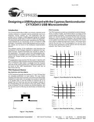
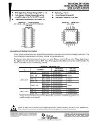
Host<br />
Interconnect<br />
Physical <strong>Device</strong><br />
Client SW<br />
manages an interface<br />
Interface x<br />
Function<br />
a collection of<br />
interfaces<br />
Pipe Bundle<br />
to an interface<br />
Buffers<br />
No <strong>USB</strong><br />
Format<br />
Interface<br />
Specific<br />
No <strong>USB</strong><br />
Format<br />
<strong>USB</strong> System SW<br />
manages devices<br />
Default Pipe<br />
to Endpoint Zero<br />
Endpoint<br />
Zero<br />
<strong>USB</strong> Logical<br />
<strong>Device</strong><br />
a collection of<br />
endpoints<br />
<strong>USB</strong> <strong>Device</strong><br />
Transfers<br />
<strong>USB</strong><br />
Framed<br />
Data<br />
Data Per<br />
Endpoint<br />
<strong>USB</strong><br />
Framed<br />
Data<br />
(Chapter 9)<br />
<strong>USB</strong> Host<br />
(Chapter 10)<br />
Host<br />
Controller<br />
<strong>USB</strong> Framed<br />
Data<br />
Transactions<br />
<strong>USB</strong> <strong>Bus</strong><br />
Interface<br />
SIE<br />
<strong>USB</strong> Wire<br />
<strong>USB</strong> <strong>Bus</strong><br />
Interface<br />
SIE<br />
Pipe, represents connection abstraction<br />
between two horizontal entities<br />
Mechanical,<br />
Data transport mechanism<br />
Electrical,<br />
<strong>USB</strong>-relevant format of transported data<br />
Protocol<br />
(Chapter 6,7,8)<br />
Figure 3<br />
Communications in <strong>the</strong> <strong>USB</strong> System<br />
<strong>Cypress</strong> Semiconductor Ver 1.03<br />
Page 5
<strong>Cypress</strong> <strong>USB</strong> Thermometer Application Note<br />
The minimum requirements for a <strong>USB</strong> device are:<br />
• Respond to <strong>the</strong> minimum <strong>USB</strong> commands per <strong>the</strong> Spec.<br />
• Observe <strong>the</strong> mechanical protocol for physically connecting to <strong>the</strong> <strong>USB</strong>.<br />
• Observe electrical protocol for electrically connecting to <strong>the</strong> <strong>USB</strong>.<br />
• Observe <strong>the</strong> <strong>USB</strong> specified data format and transport protocols.<br />
• Handle Idle condition detection and enter and leave <strong>the</strong> Suspend condition per <strong>the</strong> <strong>USB</strong><br />
Spec.<br />
• Detect <strong>the</strong> <strong>USB</strong> reset condition and take appropriate action.<br />
• Power management per <strong>the</strong> <strong>USB</strong> spec.<br />
That is quite many things to keep track of. Fortunately, many of <strong>the</strong>se issues are handled<br />
automatically by <strong>the</strong> <strong>Cypress</strong> <strong>USB</strong> Controller or are provided by <strong>Cypress</strong> in assembly code.<br />
This leaves <strong>the</strong> designer free to concentrate primarily on <strong>the</strong> application specific aspects of <strong>the</strong>ir<br />
project.<br />
<strong>Using</strong> <strong>the</strong> <strong>Cypress</strong> <strong>USB</strong> controller, <strong>the</strong>re is minimal additional hardware and software that is<br />
required to interface to <strong>the</strong> <strong>USB</strong> bus. We have broken down <strong>the</strong> items into two groups: items are<br />
handled for <strong>the</strong> designer by <strong>the</strong> <strong>Cypress</strong> <strong>USB</strong> controller (or are provided by <strong>Cypress</strong>) and items<br />
that <strong>the</strong> designer must supply.<br />
Items provided by <strong>Cypress</strong>:<br />
• Responding to <strong>the</strong> minimum <strong>USB</strong> commands per <strong>the</strong> Spec.<br />
<strong>Cypress</strong> supplies much of <strong>the</strong> needed assembly code that <strong>the</strong> controller can use to handle<br />
<strong>the</strong> standard minimum set of <strong>USB</strong> commands.<br />
ACK, NACK, and Stall responses to SETUP’s, IN’s and OUT’s are handled based on <strong>the</strong><br />
setting of only a few control bits.<br />
The <strong>Cypress</strong> <strong>USB</strong> Controller automatically sends data buffers and receives data transfers<br />
independently on both Endpoint 0 and Endpoint 1 in response to SETUP’s, IN’s and OUT’s<br />
using its 8-byte FIFO’s.<br />
The type of packet which was received (SETUP, IN, or OUT) is automatically detected by <strong>the</strong><br />
<strong>Cypress</strong> controller and is reported in status bits. The assembly code can determine what<br />
action to take based on this information.<br />
• Observing <strong>the</strong> electrical protocol for electrically connecting to <strong>the</strong> <strong>USB</strong><br />
The <strong>Cypress</strong> controller includes <strong>USB</strong> I/O drivers to connect to <strong>the</strong> bus, thus no external bus<br />
drivers are required.<br />
<strong>Cypress</strong> Semiconductor Ver 1.03<br />
Page 6
<strong>Cypress</strong> <strong>USB</strong> Thermometer Application Note<br />
• Observing <strong>the</strong> <strong>USB</strong> specified data format and transport protocols.<br />
The <strong>Cypress</strong> <strong>USB</strong> controller contains a <strong>Serial</strong> Interface Engine which performs all direct data<br />
handling on <strong>the</strong> bus (bit stuffing, NRZI encoding/decoding, etc.).<br />
It also handles basic bus protocol decoding for <strong>USB</strong> features such as Reset, Idle Detection,<br />
PID decoding, etc.<br />
• Handling Idle detection, entering and leaving <strong>the</strong> Suspend condition.<br />
<strong>Bus</strong> Idle detection is handled automatically, making it easy to determine when <strong>the</strong> <strong>USB</strong><br />
device should be put in Suspend mode.<br />
When <strong>the</strong> <strong>Cypress</strong> <strong>USB</strong> Controller is placed in Suspend mode, its on-chip power is reduced<br />
per <strong>the</strong> <strong>USB</strong> specification, automatically.<br />
The controller will automatically resume from <strong>the</strong> Suspend State on any <strong>USB</strong> activity. It may<br />
also be programmed to Resume after GPIO or Cext activity.<br />
• <strong>Bus</strong> Reset and Power-On Reset conditions are automatically detected.<br />
When a Reset is detected, <strong>the</strong> controller state is reset and program execution starts at a<br />
user-defined subroutine.<br />
The firmware can determine which event caused <strong>the</strong> reset through status bits.<br />
Items provided by <strong>the</strong> user:<br />
Each <strong>USB</strong> device has unique hardware and software characteristics that are not generic to <strong>the</strong><br />
<strong>USB</strong> system. The user must provide hardware and software development for <strong>the</strong>se areas.<br />
• Performing <strong>the</strong> correct application specific activity for each command.<br />
While <strong>Cypress</strong> provides <strong>the</strong> majority of <strong>the</strong> assembly code for handling <strong>the</strong> interface to <strong>the</strong><br />
<strong>USB</strong> and general controller activities for each command, <strong>the</strong> user must develop code for any<br />
activity that would be application specific.<br />
• Observe <strong>the</strong> mechanical protocol for physically connecting to <strong>the</strong> <strong>USB</strong><br />
Each device must provide a means for <strong>the</strong>ir device to physically attach to <strong>the</strong> <strong>USB</strong> (<strong>USB</strong><br />
Spec 1.0, 6.3). Attaching your device to <strong>the</strong> <strong>USB</strong> requires ei<strong>the</strong>r:<br />
• A <strong>USB</strong> cable with one end permanently attached to your device and a <strong>USB</strong> “A” type plug<br />
on <strong>the</strong> o<strong>the</strong>r end (to be connected to <strong>the</strong> host controller port).<br />
• A <strong>USB</strong> “B” type receptacle on your device to which a <strong>USB</strong> cable with both an “A” and a<br />
“B” plug will be attached.<br />
• Observing <strong>the</strong> electrical protocol for electrically connecting to <strong>the</strong> <strong>USB</strong>.<br />
To allow <strong>the</strong> <strong>USB</strong> hub to identify your device as a low speed device, <strong>the</strong> user must supply a<br />
pull up resistor between <strong>the</strong> “D-“ line and a positive supply voltage. This resistor can be ei<strong>the</strong>r<br />
a 1.5KOhm, 5% resistor to connected to a 3.14 V - 3.47 V supply or a 7.5KOhm, 1% resistor<br />
connected directly to <strong>the</strong> <strong>USB</strong> Vbus. (<strong>USB</strong> Spec 1.0, 7.1.3 and <strong>Device</strong> Working Group<br />
Review Request 135, 3.3V Regulator Tolerance)<br />
For more information on proper <strong>USB</strong> termination, please see <strong>the</strong> <strong>USB</strong> specification.<br />
<strong>Cypress</strong> Semiconductor Ver 1.03<br />
Page 7
<strong>Cypress</strong> <strong>USB</strong> Thermometer Application Note<br />
• Power management per <strong>the</strong> <strong>USB</strong> spec.<br />
The user must handle power shutdown and enable of external logic during Suspend and<br />
o<strong>the</strong>r stages of <strong>USB</strong> operation.<br />
<strong>Cypress</strong> Semiconductor Ver 1.03<br />
Page 8
<strong>Cypress</strong> <strong>USB</strong> Thermometer Application Note<br />
Communications Between Applications and <strong>Device</strong>s<br />
<strong>Device</strong> Drivers<br />
Applications cannot communicate directly with <strong>USB</strong> devices, and must do all communications<br />
through a device driver. In turn, <strong>the</strong> device driver will communicate with <strong>the</strong> <strong>USB</strong> device through<br />
<strong>the</strong> <strong>USB</strong> system drivers.<br />
The device driver opens pipes to endpoints on <strong>the</strong> <strong>USB</strong> device. It uses <strong>the</strong>se pipes for all<br />
communications with <strong>the</strong> device.<br />
Addresses and Endpoints<br />
The <strong>Cypress</strong> CY7C63X0X family of <strong>USB</strong> Controllers support two endpoints (0 and 1). The <strong>USB</strong><br />
device uses <strong>the</strong>se to communicate with <strong>the</strong> <strong>USB</strong> system in a manner defined by <strong>the</strong> <strong>USB</strong><br />
specification, its device driver, and its micro code.<br />
Endpoint 0, <strong>the</strong> device default control endpoint, is always configured. The <strong>USB</strong> system uses this<br />
endpoint for command and control of <strong>the</strong> device and for retrieving its status. Communications to<br />
Endpoint 0 is always through a message pipe and is bi-directional.<br />
The <strong>Cypress</strong> <strong>USB</strong> Controller supports an additional endpoint, Endpoint 1. This endpoint is<br />
unidirectional, can only be configured as an interrupt endpoint. It can be used to transmit data<br />
from <strong>the</strong> device to <strong>the</strong> host.<br />
Human Interface <strong>Device</strong>s (HID) (mice, joysticks, and keyboards, etc.), frequently use Endpoint 1<br />
to supply new information to <strong>the</strong> host on request.<br />
The <strong>Cypress</strong> <strong>USB</strong> Controller also supports a programmable address register that holds <strong>the</strong><br />
device logical address on <strong>the</strong> <strong>USB</strong>. The <strong>USB</strong> assigns this address to <strong>the</strong> device during<br />
enumeration.<br />
Enumerating a <strong>USB</strong> <strong>Device</strong><br />
For a host to use a <strong>USB</strong> device, <strong>the</strong> host must first enumerate it. This procedure allows <strong>the</strong> <strong>USB</strong><br />
system to identify <strong>the</strong> device, load its driver if necessary, assign it a logical address, and<br />
configure it. This sequence of events is called enumeration. In order for <strong>the</strong> host to use any of <strong>the</strong><br />
functions of a device, <strong>the</strong> host must first enumerate <strong>the</strong> device.<br />
Each <strong>USB</strong> device has a pull-up resistor attached between a specific positive voltage and ei<strong>the</strong>r<br />
D+ or D- signal line of <strong>the</strong> <strong>USB</strong>. This configuration indicates whe<strong>the</strong>r <strong>the</strong> device is a low-speed or<br />
full-speed device. D- pulled high indicates <strong>the</strong> device is a low-speed device while D+ pulled high<br />
indicates a full-speed device. The CY63XXX series of micro controllers are low-speed <strong>USB</strong><br />
devices.<br />
When a device is plugged into <strong>the</strong> <strong>USB</strong>, <strong>the</strong> <strong>USB</strong> system will detect <strong>the</strong> event. The <strong>USB</strong> system<br />
will determine whe<strong>the</strong>r <strong>the</strong> newly attached device is a full- or a low-speed device by determining<br />
which line (D+ or D-) is pulled high. It will also determine to which port <strong>the</strong> <strong>USB</strong> device is<br />
attached.<br />
The <strong>USB</strong> system will <strong>the</strong>n initialize <strong>the</strong> new device by sending it a <strong>USB</strong> reset. This reset will not<br />
affect any o<strong>the</strong>r device because <strong>the</strong> reset is only sent to <strong>the</strong> new devices' ports and not to <strong>the</strong><br />
o<strong>the</strong>r ports.<br />
The system will <strong>the</strong>n request <strong>the</strong> device’s <strong>Device</strong> Descriptor (see Control Transfer below) to<br />
Endpoint 0 at <strong>the</strong> default <strong>USB</strong> address, zero. The device will respond by sending its <strong>Device</strong><br />
Descriptor as requested.<br />
When <strong>the</strong> <strong>USB</strong> system has received enough of <strong>the</strong> device descriptor to determine what <strong>the</strong> newly<br />
attached device is, it will <strong>the</strong>n attempt to locate an existing driver for <strong>the</strong> device. If a driver exists,<br />
<strong>the</strong> <strong>USB</strong> System will automatically load it.<br />
If <strong>the</strong> operating system cannot locate an existing driver, it will automatically prompt <strong>the</strong> user to<br />
supply a driver, and will load <strong>the</strong> driver when <strong>the</strong> user has supplied it or its location.<br />
<strong>Cypress</strong> Semiconductor Ver 1.03<br />
Page 9
<strong>Cypress</strong> <strong>USB</strong> Thermometer Application Note<br />
Once <strong>the</strong> driver has been loaded, <strong>the</strong> host will send <strong>the</strong> device a unique logical address that will<br />
be used for all future communications.<br />
It will <strong>the</strong>n again request <strong>the</strong> device descriptor at <strong>the</strong> new address. After it completes reading <strong>the</strong><br />
device descriptor, it will <strong>the</strong>n request <strong>the</strong> configuration descriptor.<br />
Finally, <strong>the</strong> operating system and/or <strong>the</strong> driver will send <strong>the</strong> configuration information to <strong>the</strong><br />
device.<br />
This completes <strong>the</strong> process of enumeration and <strong>the</strong> host may now use any of <strong>the</strong> configured<br />
functions of <strong>the</strong> device.<br />
<strong>USB</strong> <strong>Device</strong> Communication (Packets and Transactions)<br />
The host communicates with a <strong>USB</strong> device during enumeration and operation through a series of<br />
transactions on <strong>the</strong> <strong>USB</strong>. Most communication, including <strong>the</strong> process of enumeration, is<br />
accomplished using <strong>the</strong>se transactions. At first, deciphering <strong>the</strong>se transactions may seem<br />
complex, but it is really quite simple.<br />
A transaction consists of several packets of information sent on <strong>the</strong> <strong>USB</strong>.<br />
Each transaction consists of:<br />
• A token packet<br />
This identifies <strong>the</strong> type of transaction (IN, OUT, or SETUP) and <strong>the</strong> recipient’s address and<br />
endpoint. The host is <strong>the</strong> only one that will issue a token packet. INs and OUTs correspond<br />
to IN and OUT transactions. A SETUP token is used for a Control Transfer transaction.<br />
These transactions are covered below in detail.<br />
• Some amount of data<br />
Ei<strong>the</strong>r <strong>the</strong> host or <strong>the</strong> device will send data. This can range from zero to some number of<br />
bytes. The direction of <strong>the</strong> transfer will be indicated in <strong>the</strong> token. IN and OUT transactions<br />
transmit data from device to host or from host to device, respectively. The size of <strong>the</strong> transfer<br />
is determined by <strong>the</strong> context of <strong>the</strong> transaction. SETUP transactions always contain eight<br />
bytes of data sent from <strong>the</strong> host to <strong>the</strong> device. They are simply a special form of an OUT<br />
transaction.<br />
• A handshake packet<br />
This will indicate <strong>the</strong> status of a data transfer in a transaction.<br />
The <strong>Cypress</strong> <strong>USB</strong> Controller automatically decodes <strong>the</strong>se packets, and provides <strong>the</strong> information<br />
contained in easy-to-use status and data locations. The designer can <strong>the</strong>n use this information in<br />
assembly code routines to determine what action to take. Since <strong>the</strong> designer does not need to<br />
handle <strong>the</strong>se packets individually, we will not discuss <strong>the</strong>m in detail here.<br />
The designer does need to handle <strong>the</strong> transactions, which are made up of <strong>the</strong>se packets.<br />
Transaction Types (INs, OUTs, and Control Transfers)<br />
We need to be concerned with three types of transactions. They are INs, OUTs, and Control<br />
Transfers.<br />
<strong>Cypress</strong> Semiconductor Ver 1.03<br />
Page 10
<strong>Cypress</strong> <strong>USB</strong> Thermometer Application Note<br />
IN’s and OUT’s<br />
• An “IN” tells <strong>the</strong> device to send <strong>the</strong> data that <strong>the</strong> host is expecting.<br />
• An “OUT” tells <strong>the</strong> device to take <strong>the</strong> data <strong>the</strong> host will send.<br />
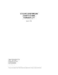
Figure 4 shows <strong>the</strong> structure of INs and OUTs. You can see that <strong>the</strong>y consist of three packets:<br />
• A token identifying <strong>the</strong> transaction as an IN or OUT.<br />
The host always sends this.<br />
• The data<br />
Data ei<strong>the</strong>r is sent by <strong>the</strong> device or host. The source of <strong>the</strong> data is dependent on whe<strong>the</strong>r <strong>the</strong><br />
transaction is an IN or OUT respectively.<br />
• A handshake<br />
The recipient of <strong>the</strong> data sends this to indicate whe<strong>the</strong>r or not <strong>the</strong> transfer was successful.<br />
Idle<br />
Token<br />
IN OUT<br />
Data<br />
DATA0/<br />
DATA1<br />
NAK<br />
STALL<br />
DATA0/<br />
DATA1<br />
Idle<br />
ACK<br />
ACK<br />
NAK<br />
STALL<br />
Idle<br />
Host<br />
Function<br />
Figure 4<br />
Data Transfer Transaction<br />
IN and OUT transactions may occur singly or as part of a larger sequence.<br />
When used singly, an IN transaction is used by a host to communicate with an interrupt endpoint<br />
(such as Endpoint 1 on <strong>the</strong> <strong>Cypress</strong> <strong>USB</strong> Controller) in order to retrieve data from <strong>the</strong> device. An<br />
example would be a host retrieving position information from a mouse on a regular basis.<br />
When used this way, <strong>the</strong> host must first configure <strong>the</strong> device to respond to <strong>the</strong> INs on Endpoint 1<br />
by communicating on Endpoint 0 with control transfers.<br />
<strong>Cypress</strong> Semiconductor Ver 1.03<br />
Page 11
<strong>Cypress</strong> <strong>USB</strong> Thermometer Application Note<br />
An IN or OUT can also be used as part of a larger sequence of transactions called a Control<br />
Transfer. In a control transfer (see below), INs or OUTs are used both to transfer data and to<br />
return status to <strong>the</strong> host.<br />
Control Transfers<br />
A host needs to be able to communicate with a device to control it or obtain its status. This is<br />
done through <strong>the</strong> device’s Endpoint 0 using control transfers. A control transfer is simply a special<br />
series of transactions in a specific sequence between a host and a control endpoint (Endpoint 0).<br />
Control transfers are used by a host to enumerate a device or change its state in any way, or<br />
obtain its status. Control transfers may also be used to send data to a device (although this is not<br />
<strong>the</strong> original intention of a control transfer).<br />
A control transfer has at least two transaction stages (a SETUP stage and a Status stage). It may<br />
also have an optional data stage, which consists of one or more IN or OUT transactions.<br />
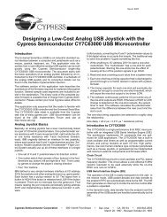
The SETUP stage is illustrated in Figure 5.<br />
There are three types of Control Transfers: a Control Read, a Control Write, and a No-data<br />
Control.<br />
The three types are illustrated in Figure 6.<br />
SETUP Stage<br />
The SETUP stage (See Figure 5) consists of three packets: <strong>the</strong> SETUP token, eight bytes of<br />
data, and <strong>the</strong> handshake packet.<br />
A “SETUP” is a special type of “OUT” that gives a specific command to <strong>the</strong> <strong>USB</strong> device to do<br />
something.<br />
Idle<br />
Token<br />
SETUP<br />
Data<br />
DATA0<br />
Handshake<br />
ACK<br />
Idle<br />
Host<br />
Function<br />
Figure 5<br />
Control SETUP Transaction<br />
<strong>Cypress</strong> Semiconductor Ver 1.03<br />
Page 12
<strong>Cypress</strong> <strong>USB</strong> Thermometer Application Note<br />
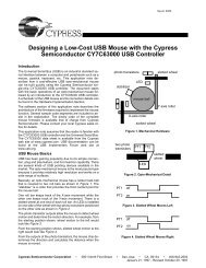
Data Stage<br />
The data stage, if it exists, consists of one or more IN or OUT transactions (See Figure 6), <strong>the</strong><br />
direction and number of which are specified in <strong>the</strong> SETUP stage. All transactions in <strong>the</strong> data<br />
stage must be in <strong>the</strong> same direction, i.e. ei<strong>the</strong>r all INs or all OUTs.<br />
Setup<br />
Stage<br />
Data<br />
Stage<br />
Status<br />
Stage<br />
Control<br />
Write<br />
SETUP (0) OUT (1) OUT (0)<br />
OUT (0/1)<br />
DATA0<br />
DATA1<br />
DATA0<br />
DATA0/1<br />
...<br />
IN (1)<br />
DATA1<br />
Control<br />
Read<br />
SETUP (0)<br />
DATA0<br />
IN (1)<br />
DATA1<br />
...<br />
IN (0) IN (0/1)<br />
DATA0<br />
DATA0/1<br />
OUT (1)<br />
DATA1<br />
Setup<br />
Stage<br />
Status<br />
Stage<br />
No-data<br />
Control<br />
SETUP (0)<br />
DATA0<br />
IN (1)<br />
DATA1<br />
Figure 6<br />
Control Read and Write Sequences<br />
Status Stage<br />
In all three types of Control Transfers, <strong>the</strong> Status stage is an IN or an OUT (See Figure 6).<br />
Additionally, <strong>the</strong> status stage has a data size of zero bytes and has a direction that is <strong>the</strong> opposite<br />
of <strong>the</strong> direction of <strong>the</strong> previous transfer. Since <strong>the</strong> SETUP is actually a special OUT, <strong>the</strong> Status<br />
stage for a No-data Control is an IN. The Status stage is also a zero byte transfer (an IN or an<br />
OUT with no data).<br />
In a Control Read or Write, <strong>the</strong> Setup will specify how many bytes of data are to be read or<br />
written. However, if <strong>the</strong> Host enters a Status stage prior to completing <strong>the</strong> transfer of data, all<br />
fur<strong>the</strong>r data transfers for that Control Transfer are canceled. The host can enter <strong>the</strong> Status stage<br />
by issuing an IN during a Control Write or an OUT with a zero byte data length during a Control<br />
Read.<br />
How Control Transfers are Used<br />
Control transfers are like a command and response between <strong>the</strong> host and <strong>the</strong> <strong>USB</strong> device. They<br />
are simple and well defined in <strong>the</strong> <strong>USB</strong> Specification.<br />
When a SETUP packet is received by <strong>the</strong> device, <strong>the</strong> device knows that it is receiving a Control<br />
Transfer. It decodes <strong>the</strong> SETUP to determine what to do with <strong>the</strong> following data (if any), and <strong>the</strong>n<br />
proceeds accordingly.<br />
Control Transfers handle most stages of <strong>the</strong> enumeration process: Get <strong>Device</strong> Descriptor, Set<br />
Address, Get Configuration Descriptor, and Set Configuration.<br />
Since Control Transfers are used for fundamental control of <strong>the</strong> device, <strong>the</strong>y are very critical.<br />
<strong>Cypress</strong> provides assembly language routines to handle <strong>the</strong> common control transfers <strong>the</strong> device<br />
will receive. The designer should be familiar with <strong>the</strong>m in order to be able to add <strong>the</strong> device<br />
specific requirements of <strong>the</strong>ir design. These routines are located in <strong>USB</strong>.ASM on <strong>the</strong> <strong>Cypress</strong><br />
<strong>USB</strong> CD-ROM.<br />
The specifics of each of <strong>the</strong> Control Transfers can be found in <strong>the</strong> <strong>USB</strong> Spec, Chapter 9, "<strong>USB</strong><br />
<strong>Device</strong> Framework".<br />
<strong>Cypress</strong> Semiconductor Ver 1.03<br />
Page 13
<strong>Cypress</strong> <strong>USB</strong> Thermometer Application Note<br />
Powering a <strong>USB</strong> <strong>Device</strong><br />
The <strong>USB</strong> system limits both <strong>the</strong> total power, which <strong>the</strong> <strong>USB</strong> bus can supply for all devices, and<br />
<strong>the</strong> power consumed by a single device.<br />
<strong>Bus</strong> Powered <strong>Device</strong>s<br />
A <strong>USB</strong> device may receive all or part of its power directly from <strong>the</strong> <strong>USB</strong>. However, <strong>the</strong> <strong>USB</strong><br />
specification limits <strong>the</strong> amount of current a device can draw from <strong>the</strong> <strong>USB</strong>. This amount depends<br />
on:<br />
1. The state of <strong>the</strong> device<br />
• Powered<br />
Prior to <strong>the</strong> device completing enumeration, power consumption is limited to one unit load<br />
(100 mA). This is a maximum value, and not an average value. (<strong>USB</strong> Spec 1.0, 7.2.1,<br />
<strong>USB</strong> Core Specification Clarifications by Section, rr97)<br />
• Configured<br />
Once configured, <strong>the</strong>re are two classes of devices in terms of power consumption: low<br />
power devices and high power devices.<br />
Low-power devices may draw no more than one unit load (100 mA) from <strong>the</strong> <strong>USB</strong>.<br />
High-power devices may increase <strong>the</strong>ir power consumption to five unit loads (500 mA) or<br />
<strong>the</strong> maximum power <strong>the</strong>y have specified during enumeration.<br />
• Operating Power Drain<br />
Once configured, a device may draw as much power as allowed by <strong>the</strong> <strong>USB</strong><br />
specification.<br />
• Suspended<br />
When a device is in Suspend Mode its power drain is limited to 500 µA. This includes <strong>the</strong><br />
power consumed by <strong>the</strong> pull-up configuration resistor on <strong>the</strong> D+ or D- line.<br />
2. The type of Hub to which it is attached<br />
Hubs can supply different amounts of current to <strong>the</strong>ir ports depending on whe<strong>the</strong>r <strong>the</strong>y are<br />
self-powered or bus-powered.<br />
A device may draw up to 500 mA from <strong>the</strong> <strong>USB</strong> if it is attached to a self-powered hub.<br />
If a device is attached to a bus-powered hub, it may only draw up to 100 mA from <strong>the</strong> <strong>USB</strong>.<br />
The hub in <strong>the</strong> desktop PC is usually considered a self-powered hub. However, <strong>the</strong> hub in a<br />
portable PC might be considered a bus-powered hub. (<strong>USB</strong> Specification 1.0, 7.2.1)<br />
If your device is a high powered device, it may exceed <strong>the</strong> available <strong>USB</strong> power from some<br />
hubs or in combination with o<strong>the</strong>r <strong>USB</strong> devices. If <strong>the</strong> power requirements are exceeded, it<br />
may become necessary to convert <strong>the</strong> design to “self-power” instead of “bus-power.”<br />
3. The maximum current that <strong>the</strong> device has told <strong>the</strong> <strong>USB</strong> system it will need<br />
The maximum amount of power a device will draw from <strong>the</strong> <strong>USB</strong> is specified in <strong>the</strong><br />
configuration descriptor.<br />
This value is read <strong>the</strong> by <strong>the</strong> <strong>USB</strong> system during enumeration.<br />
<strong>Cypress</strong> Semiconductor Ver 1.03<br />
Page 14
<strong>Cypress</strong> <strong>USB</strong> Thermometer Application Note<br />
4. Supply voltage range<br />
The voltage supplied by a <strong>USB</strong> hub at its “A” connector may be between 4.4Vdc and<br />
5.25Vdc.<br />
There may be additional loss in <strong>the</strong> cable between <strong>the</strong> “A” connector and <strong>the</strong> device itself.<br />
<strong>Bus</strong>-powered low-power devices with detachable cables must be able to enumerate correctly<br />
with supply voltages between 4.15Vdc and 5.25Vdc at <strong>the</strong> device. <strong>Bus</strong> powered devices with<br />
an attached cable must be able to enumerate with a supply voltage between 4.4Vdc and<br />
5.25Vdc at <strong>the</strong> “A” connector of <strong>the</strong> cable (<strong>USB</strong> Spec 1.0, 7.2.1.3).<br />
All bus-powered devices must be able to continue normal operations when <strong>the</strong> supply voltage<br />
at <strong>the</strong> device momentarily drops to 4.0Vdc.<br />
Self-Powered <strong>Device</strong>s<br />
Self-powered devices may use a combination of power from <strong>the</strong> <strong>USB</strong> and a local source. They<br />
must meet <strong>the</strong> same requirements as a bus-powered device in regards to <strong>the</strong> power <strong>the</strong>y draw<br />
from <strong>the</strong> <strong>USB</strong>. However, <strong>the</strong> self-powered portion of <strong>the</strong> design is solely limited by <strong>the</strong> capabilities<br />
of <strong>the</strong> external power supply.<br />
<strong>Cypress</strong> Semiconductor Ver 1.03<br />
Page 15
<strong>Cypress</strong> <strong>USB</strong> Thermometer Application Note<br />
<strong>Designing</strong> <strong>the</strong> “<strong>Cypress</strong> <strong>USB</strong> Thermometer”<br />
Overview of <strong>the</strong> <strong>Cypress</strong> <strong>USB</strong> Thermometer system<br />
The goal of this project was to produce a low cost system that would display temperature from a<br />
remote device.<br />
This application note documents <strong>the</strong> design of this system using <strong>the</strong> <strong>Cypress</strong> CY7C63001 <strong>USB</strong><br />
controller chip to implement <strong>the</strong> <strong>USB</strong> <strong>the</strong>rmometer.<br />
It provides:<br />
• A set of common <strong>USB</strong> assembly language routines which are usable by <strong>Cypress</strong> <strong>USB</strong><br />
controllers to communicate with <strong>the</strong> <strong>USB</strong> system.<br />
• A set of assembly language routines which are usable by <strong>Cypress</strong> <strong>USB</strong> controllers for<br />
performing serial I/O to external logic.<br />
• <strong>USB</strong> hardware design guidelines for implementing a <strong>USB</strong> device using <strong>Cypress</strong> <strong>USB</strong><br />
controllers.<br />
Partitioning <strong>the</strong> elements of our <strong>USB</strong> based system<br />
The basic elements of <strong>the</strong> system are:<br />
• A Windows application to acquire <strong>the</strong> temperature from <strong>the</strong> <strong>USB</strong> device and display it for <strong>the</strong><br />
user.<br />
• A <strong>USB</strong> enabled host PC and OS (with <strong>the</strong> appropriate drivers) to run <strong>the</strong> application and<br />
provide <strong>the</strong> <strong>USB</strong> hardware and software interface.<br />
• A <strong>USB</strong> device which will connect to <strong>the</strong> <strong>USB</strong>, measure <strong>the</strong> temperature and communicate<br />
that measurement to <strong>the</strong> host.<br />
Figure 7 illustrates <strong>the</strong> elements of <strong>the</strong> temperature measurement and display system.<br />
<strong>Cypress</strong> Semiconductor Ver 1.03<br />
Page 16
<strong>Cypress</strong> <strong>USB</strong> Thermometer Application Note<br />
Windows<br />
Application<br />
- Thermometer -<br />
OS with <strong>USB</strong><br />
Support<br />
(OSR2.1 or Memphis)<br />
<strong>USB</strong> Enabled Host PC<br />
<strong>USB</strong> <strong>Device</strong><br />
CY3640<br />
<strong>USB</strong> Controller<br />
(CY7C63001)<br />
Temperature Sensor<br />
Figure 7<br />
Elements of a <strong>USB</strong> System<br />
A complete schematic of <strong>the</strong> <strong>Cypress</strong> <strong>USB</strong> Thermometer device is shown in Figure 8.<br />
<strong>Cypress</strong> Semiconductor Ver 1.03<br />
Page 17
<strong>Cypress</strong> <strong>USB</strong> Thermometer Application Note<br />
Figure 8<br />
CY3640 Schematic<br />
<strong>Cypress</strong> Semiconductor Ver 1.03<br />
Page 18
<strong>Cypress</strong> <strong>USB</strong> Thermometer Application Note<br />
Partitioning <strong>the</strong> <strong>Cypress</strong> <strong>USB</strong> Thermometer device<br />
There are four main sub-systems in <strong>the</strong> <strong>Cypress</strong> <strong>USB</strong> Thermometer device:<br />
• The <strong>USB</strong> interface<br />
• The temperature sensor interface<br />
• The enumeration LED<br />
• The Centigrade/Fahrenheit button<br />
Overview<br />
All <strong>USB</strong> communication between <strong>the</strong> host and <strong>the</strong> <strong>the</strong>rmometer occurs on an interrupt basis in <strong>the</strong><br />
Endpoint 0 interrupt service routine.<br />
After a reset, <strong>the</strong> system is started in <strong>the</strong> main() routine in <strong>USB</strong>.ASM. This routine initializes <strong>the</strong><br />
<strong>USB</strong> variables, <strong>the</strong> IO ports, <strong>the</strong> temperature sensor variables, and <strong>the</strong> data space. The system<br />
loops here, doing nothing except responding to <strong>USB</strong> Commands until <strong>the</strong> device has been<br />
enumerated.<br />
Once <strong>the</strong> device is enumerated, <strong>the</strong> main routine also polls <strong>the</strong> temperature sensor approximately<br />
once every 10 ms to retrieve <strong>the</strong> new temperature reading, and updates <strong>the</strong> brightness of <strong>the</strong><br />
enumeration LED if necessary.<br />
The enumeration LED is controlled by <strong>the</strong> P13 pin of <strong>the</strong> <strong>USB</strong> controller and is turned on when a<br />
SetConfiguration command is received. This routine is decoded in <strong>USB</strong>.ASM.<br />
An external sensor senses <strong>the</strong> temperature and all communication between <strong>the</strong> <strong>Cypress</strong> <strong>USB</strong><br />
Controller and <strong>the</strong> sensor is through Port 0 using pins P00, P01, and P02. These routines are<br />
contained in DS1620.ASM.<br />
The controller detects button presses using Port 1, pin P12. Routines which support button press<br />
detection are found in <strong>the</strong> GPIO interrupt servicing routine and <strong>the</strong> 1024 µs interrupt service<br />
routine in <strong>USB</strong>.ASM.<br />
The <strong>USB</strong> electrical and mechanical interface<br />
• Identifying <strong>the</strong> device as a low-speed device<br />
To allow <strong>the</strong> <strong>USB</strong> hub to identify our device as a low-speed device, we must supply a pull up<br />
resistor between <strong>the</strong> “D-“ line and a positive supply voltage. We chose a 7.5 KOhm, 1%<br />
resistor connected directly to <strong>the</strong> <strong>USB</strong> Vbus. (<strong>USB</strong> Spec 1.0, 7.1.3 and <strong>Device</strong> Working<br />
Group Review Request 135, 3.3V Regulator Tolerance)<br />
It is important to insure that, if your device is self-powered, it cannot drive current into a<br />
floating upstream I/O driver. Supplying <strong>the</strong> power connected to <strong>the</strong> pull-up resistor from <strong>the</strong><br />
<strong>USB</strong> Vbus is an easy way to insure this, and is independent of whe<strong>the</strong>r or not your device is<br />
self-powered. (<strong>USB</strong> Spec 1.0, 7.1.3 and <strong>USB</strong> Core Specification Clarifications rr90)<br />
• Physically connecting <strong>the</strong> device to <strong>the</strong> <strong>USB</strong><br />
We chose to use a B type receptacle on our PC board. This allows us to use a detachable<br />
<strong>USB</strong> cable. However, <strong>the</strong> board also provides an in-line header footprint which <strong>the</strong> developer<br />
may use to hardwire a <strong>USB</strong> cable directly to <strong>the</strong> board.<br />
The <strong>USB</strong> Protocol Interface<br />
The routines for <strong>the</strong> functions that support this interface are located in <strong>USB</strong>.ASM.<br />
<strong>Cypress</strong> Semiconductor Ver 1.03<br />
Page 19
<strong>Cypress</strong> <strong>USB</strong> Thermometer Application Note<br />
We communicate with one endpoint (Endpoint 0) by a pipe that supports both system and vendor<br />
specific communications.<br />
Endpoint zero is required to support Setup oriented requests and o<strong>the</strong>r class or vendor requests.<br />
Each request interrupts <strong>the</strong> processor through <strong>the</strong> Endpoint 0 Interrupt service routine found in<br />
<strong>USB</strong>.ASM. This routine determines whe<strong>the</strong>r or not <strong>the</strong> request causing <strong>the</strong> interrupt was a<br />
SETUP command. If <strong>the</strong> request was a SETUP, <strong>the</strong> command is decoded and <strong>the</strong> subsequent<br />
routines service it.<br />
When a token is received by Endpoint 0, <strong>the</strong> <strong>Cypress</strong> <strong>USB</strong> Controller’s <strong>Serial</strong> Interface Engine<br />
(SIE) automatically determines if it is a SETUP packet. If <strong>the</strong> token is a Setup token, <strong>the</strong> SIE<br />
automatically places <strong>the</strong> associated data in Endpoint 0’s FIFO.<br />
It is only left to <strong>the</strong> designer to:<br />
• Determine <strong>the</strong> type of Control Transfer that is indicated by <strong>the</strong> SETUP packet from data in <strong>the</strong><br />
FIFO<br />
• Respond appropriately to <strong>the</strong> subsequent INs or OUTs based on <strong>the</strong> type of SETUP packet<br />
received<br />
• Respond correctly to <strong>the</strong> status transaction<br />
<strong>Cypress</strong> supplies assembly language routines to accomplish this for <strong>the</strong> standard <strong>USB</strong><br />
commands <strong>the</strong> device will receive. These are found in <strong>USB</strong>.ASM.<br />
Two vendor-specific control transfers are supported by <strong>the</strong> assembly code: GetTemperature and<br />
SetBrightness.<br />
When <strong>the</strong> controller receives a GetTemperature control transfer from <strong>the</strong> host, <strong>the</strong> last measured<br />
temperature reading is returned, along with a value, which indicates whe<strong>the</strong>r or not <strong>the</strong> button has<br />
been pushed since <strong>the</strong> last check.<br />
When <strong>the</strong> controller receives a SetBrightness control transfer from <strong>the</strong> host, <strong>the</strong> brightness level<br />
of <strong>the</strong> enumeration LED is changed according to <strong>the</strong> value specified in <strong>the</strong> control transfer.<br />
The Temperature Sensing Logic<br />
Since <strong>the</strong> <strong>Cypress</strong> <strong>USB</strong> Controller is a microcontroller with excellent control of its ports, no<br />
external logic was necessary to interface to <strong>the</strong> temperature-sensing chip.<br />
The temperature-sensing logic required three signals: reset, clock, and data (IN/OUT). All signals<br />
required to operate <strong>the</strong> temperature-sensing device were controlled by micro code.<br />
Port 0 is a low drive port and is suitable for use with low power devices such as CMOS and photo<br />
detectors. The temperature sensor is a CMOS device so Port 0 was used (P00 – P02).<br />
The routines for <strong>the</strong>se functions are primarily located in DS1620.ASM.<br />
A set of routines for generating timing signals was developed. These routines are generic for<br />
generating any set of signals commonly needed for this type of purpose.<br />
The assembly code for this interface can be found in files DS1620.ASM and DS1620.INC on <strong>the</strong><br />
CDROM.<br />
A simple 9-bit temperature value is read from <strong>the</strong> temperature sensor every 10 ms. After<br />
enumeration, <strong>the</strong> temperature sensor is initialized and placed into a continuous conversion mode.<br />
It stores <strong>the</strong> current temperature internally. Thereafter, <strong>the</strong> temperature is read every 10 ms and<br />
<strong>the</strong> value is placed into <strong>the</strong> <strong>USB</strong> endpoint one FIFO buffer for temporary storage.<br />
When a “Read Temperature” command is decoded, it is copied from <strong>the</strong> EP1 FIFO along with <strong>the</strong><br />
button status and placed into <strong>the</strong> EP0 FIFO where it will be returned to <strong>the</strong> host as part of <strong>the</strong><br />
command.<br />
<strong>Cypress</strong> Semiconductor Ver 1.03<br />
Page 20
<strong>Cypress</strong> <strong>USB</strong> Thermometer Application Note<br />
The Enumeration LED<br />
The LED is controlled by I/O Port P13. Port 1 has high drive capability and is capable of driving<br />
LEDs and o<strong>the</strong>r high current circuitry. The LED draws 20 mA and so Port 1 (P13) was chosen to<br />
drive it.<br />
When P13 goes low, this turns <strong>the</strong> LED on. The LED indicates <strong>the</strong> status of <strong>the</strong> <strong>USB</strong> connection.<br />
Once this device has been enumerated, <strong>the</strong> LED is turned on. This occurs in <strong>the</strong> SetConfiguration<br />
routine in <strong>USB</strong>.ASM.<br />
A Vendor Specific Control Transfer, Set Brightness, is supported to allow us to adjust <strong>the</strong><br />
brightness of <strong>the</strong> LED. This passes <strong>the</strong> new brightness level to <strong>the</strong> controller.<br />
To change <strong>the</strong> brightness of <strong>the</strong> LED we use a feature of <strong>the</strong> <strong>Cypress</strong> <strong>USB</strong> Controller that allows<br />
us to set <strong>the</strong> strength of <strong>the</strong> output buffer of each port. We adjust <strong>the</strong> LED’s brightness by first<br />
setting <strong>the</strong> new brightness value (default: FFh = High) and <strong>the</strong>n setting <strong>the</strong> brightness update<br />
field.<br />
The routine MAIN in <strong>USB</strong>.ASM checks <strong>the</strong> update variable and sets <strong>the</strong> new brightness by<br />
loading <strong>the</strong> value of <strong>the</strong> brightness variable into <strong>the</strong> P13 port strength register if necessary.<br />
The Centigrade/Fahrenheit Button<br />
A push button switch is used to indicate to <strong>the</strong> Windows application that <strong>the</strong> user wants <strong>the</strong><br />
Centigrade/Fahrenheit display mode to be toggled.<br />
The switch is a normally open momentary closed device. One side of <strong>the</strong> switch is connected to<br />
P12 and is also pulled high by a 10K resistor to Vcc. Thus, normally, P12 is held high.<br />
Alternatively, it could be pulled high by using <strong>the</strong> selectable on chip pull up resistor on <strong>the</strong><br />
controller. This would eliminate <strong>the</strong> need for an external component.<br />
The o<strong>the</strong>r side of <strong>the</strong> switch is connected to Vss.<br />
When <strong>the</strong> switch is pushed, P12 is grounded.<br />
This is illustrated in Figure 9.<br />
We have programmed <strong>the</strong> <strong>Cypress</strong> controller to give a GPIO interrupt on <strong>the</strong> Low-to-High<br />
transition of P12.<br />
Any time this transition occurs, <strong>the</strong> GPIO interrupt routine sets a variable, gbButtonDebounce, to<br />
100.<br />
The 1024 µs interrupt routine decrements this variable approximately each millisecond.<br />
If <strong>the</strong> routine decrements <strong>the</strong> variable to zero, it checks to see if <strong>the</strong> port has returned to a high.<br />
If P12 is now high, <strong>the</strong> routine determines that a valid button press and release has occurred.<br />
If <strong>the</strong> port has not returned to a high state, <strong>the</strong> routine determines that <strong>the</strong> button has not yet been<br />
released or is bouncing and, resets <strong>the</strong> variable to 100. The process is <strong>the</strong>n repeated.<br />
<strong>Cypress</strong> Semiconductor Ver 1.03<br />
Page 21
<strong>Cypress</strong> <strong>USB</strong> Thermometer Application Note<br />
P12<br />
Figure 9<br />
The Centigrade/Fahrenheit Button<br />
The <strong>Cypress</strong> Watchdog Timer<br />
The <strong>Cypress</strong> watchdog timer is not used in our application, but it deserves mention here.<br />
This timer increments once each millisecond. If it reaches a count of eight, <strong>the</strong> <strong>Cypress</strong> <strong>USB</strong><br />
Controller will be reset. It is cleared by any write to <strong>the</strong> Watchdog Timer Register at I/O address<br />
21h.<br />
The timer can be used to help determine if your device has gotten into an inappropriate state from<br />
which it cannot recover. An example would be if it were caught in a loop, unable to get out. After<br />
eight ms, <strong>the</strong> watchdog timer would time out and <strong>the</strong> device would be reset.<br />
The watchdog timer cannot be disabled directly. However, placing a write to <strong>the</strong> Watchdog Timer<br />
Register at I/O address 21h in <strong>the</strong> 1024 µs interrupt-handling loop will constantly clear <strong>the</strong><br />
counter. This is an effective method of disabling <strong>the</strong> watchdog counter, since <strong>the</strong> only<br />
inappropriate event or condition that could cause it to reset <strong>the</strong> controller would be if <strong>the</strong> 1ms<br />
timer interrupt were disabled.<br />
The Windows Application<br />
The Thermometer application queries <strong>the</strong> <strong>USB</strong> <strong>the</strong>rmometer and displays <strong>the</strong> temperature. The<br />
application can display <strong>the</strong> temperature over time for <strong>the</strong> last 64 samples. The sample rate<br />
displayed varies from one sample per second to one sample every 30 hours.<br />
Communicating with <strong>USB</strong> devices<br />
A normal Windows application cannot communicate directly with a <strong>USB</strong> device. All<br />
communications with a device are through a <strong>USB</strong> device driver. This driver will be automatically<br />
loaded when a <strong>USB</strong> device is attached to <strong>the</strong> <strong>USB</strong> bus and automatically unloaded when <strong>the</strong><br />
device is detached.<br />
To communicate with a <strong>USB</strong> device, three Windows APIs are used: OpenFile(),<br />
<strong>Device</strong>IoCommand(), and CloseHandle().<br />
• Starting communication with a <strong>USB</strong> device<br />
In order to communicate with a <strong>USB</strong> device, an application must first open a handle to its<br />
driver. This is done with <strong>the</strong> OpenFile() Windows API.<br />
To use this API, you supply <strong>the</strong> name of <strong>the</strong> driver, and information about how you want to<br />
talk to <strong>the</strong> device (read, write, etc.).<br />
If <strong>the</strong> device has been successfully attached to <strong>the</strong> <strong>USB</strong>, a device driver will have been<br />
automatically loaded, and <strong>the</strong> OpenFile() API will succeed and will return a handle to <strong>the</strong><br />
driver. O<strong>the</strong>rwise, an error return will result.<br />
<strong>Cypress</strong> Semiconductor Ver 1.03<br />
Page 22
<strong>Cypress</strong> <strong>USB</strong> Thermometer Application Note<br />
• Talking to <strong>the</strong> device<br />
Once <strong>the</strong> application software has received a handle to <strong>the</strong> device driver, it can start<br />
communicating with <strong>the</strong> device with <strong>the</strong> <strong>Device</strong>IoCommand() API.<br />
The device driver and various <strong>USB</strong> system drivers handle all actual communications with <strong>the</strong><br />
device itself. The style of <strong>the</strong> communications is varied and is device and driver dependent.<br />
In <strong>the</strong> case of <strong>the</strong> Thermometer driver, <strong>the</strong> application software simply passes messages to<br />
<strong>the</strong> driver and receives results back from <strong>the</strong> driver.<br />
• Ending communication with a <strong>USB</strong> device<br />
When <strong>the</strong> application is through communicating with <strong>the</strong> device, <strong>the</strong> handle to <strong>the</strong> device<br />
driver should be released with <strong>the</strong> CloseHandle() API.<br />
• Example code:<br />
Visual Basic 5 Function Declares<br />
Declare Function CreateFile Lib "kernel32" Alias "CreateFileA" (ByVal lpFileName<br />
As String, ByVal dwDesiredAccess As Long, ByVal dwShareMode As Long,<br />
lpSecurityAttributes As SECURITY_ATTRIBUTES, ByVal dwCreationDisposition As<br />
Long, ByVal dwFlagsAndAttributes As Long, ByVal hTemplateFile As Long) As Long<br />
Declare Function <strong>Device</strong>IoControl Lib "kernel32" (ByVal h<strong>Device</strong> As Long, ByVal<br />
dwIoControlCode As Long, lpInBuffer As Any, ByVal nInBufferSize As Long,<br />
lpOutBuffer As Any, ByVal nOutBufferSize As Long, lpBytesReturned As Long,<br />
lpOverlapped As OVERLAPPED) As Long<br />
Declare Function CloseHandle Lib "kernel32" (ByVal hObject As Long) As Long<br />
Visual Basic 5 Sample Code<br />
Type SECURITY_ATTRIBUTES<br />
nLength As Long<br />
lpSecurityDescriptor As Long<br />
bInheritHandle As Long<br />
End Type<br />
Type OVERLAPPED<br />
Internal As Long<br />
InternalHigh As Long<br />
offset As Long<br />
OffsetHigh As Long<br />
hEvent As Long<br />
End Type<br />
Public Security As SECURITY_ATTRIBUTES<br />
Public gOverlapped As OVERLAPPED<br />
Public hgDrvrHnd As LONG<br />
Public Const GENERIC_READ = &H80000000<br />
Public Const GENERIC_WRITE = &H40000000<br />
Public Const FILE_SHARE_WRITE = &H2<br />
Public Const FILE_SHARE_READ = &H1<br />
Public Const OPEN_EXISTING = &H3<br />
Dim sFileName as STRING<br />
Dim htemp As LONG<br />
<strong>Cypress</strong> Semiconductor Ver 1.03<br />
Page 23
<strong>Cypress</strong> <strong>USB</strong> Thermometer Application Note<br />
Dim lIn as long, lInSize as long, lOut as long, lOutSize as long, lSize as long<br />
sFileName = "\\.\Thermometer_0"<br />
lIn = 11 ‘ Read Temperature Command<br />
lSize = 0<br />
lInSize = 2<br />
lOutSize = 3<br />
‘ Get a handle to <strong>the</strong> driver<br />
hgDrvrHnd = CreateFile(sFileName, GENERIC_WRITE Or GENERIC_READ,<br />
FILE_SHARE_WRITE Or FILE_SHARE_READ, Security, OPEN_EXISTING, 0, 0)<br />
‘ Send <strong>the</strong> “GetTemperature Command”<br />
ltemp = <strong>Device</strong>IoControl(hgDrvrHnd, 4&, lIn, lInSize, lOut, lOutSize, lSize,<br />
gOverlapped)<br />
‘ Close <strong>the</strong> Handle to <strong>the</strong> driver<br />
htemp = CloseHandle(hgDrvrHnd)<br />
The <strong>Cypress</strong> <strong>USB</strong> Thermometer Driver<br />
Because <strong>the</strong> <strong>Cypress</strong> <strong>USB</strong> Thermometer does not fall into one of <strong>the</strong> currently supported classes<br />
of devices, <strong>Cypress</strong> wrote a vendor specific driver to accommodate <strong>the</strong> project. In <strong>the</strong> future, an<br />
official <strong>USB</strong> class will undoubtedly support a <strong>the</strong>rmometer type of device, and <strong>the</strong> writing of a<br />
driver for this type of product would no longer be required. It is useful, in this application note, to<br />
illustrate communication with custom driver software. For many classes of devices, class drivers<br />
will be available with <strong>the</strong> operating system. However, for custom functionality or performance<br />
enhancement, a custom driver may be preferred over a generic “class driver.”<br />
See <strong>the</strong> “CY3640 User’s Guide” for documentation on <strong>the</strong> calls to <strong>the</strong> driver using <strong>the</strong><br />
<strong>Device</strong>IoControl() function from <strong>the</strong> above source code example.<br />
<strong>Cypress</strong> Semiconductor Ver 1.03<br />
Page 24
<strong>Cypress</strong> <strong>USB</strong> Thermometer Application Note<br />
Connecting to <strong>the</strong> <strong>Bus</strong><br />
General Hardware Design Considerations<br />
Noise<br />
Noise coupled to and from D+ and D- and Power lines can cause problems with both EMI and/or<br />
data errors.<br />
D+ and D- should be kept away from signals that could couple noise to or from <strong>the</strong>m such as<br />
clock lines or o<strong>the</strong>r high frequency signals. A good ground plane under <strong>the</strong>se lines and/or<br />
shielding traces around <strong>the</strong>m should be sufficient to minimize coupled noise to or from <strong>the</strong>se<br />
lines.<br />
Good bulk and high frequency bypassing techniques should be used where <strong>the</strong> <strong>USB</strong> Vbus<br />
connects to <strong>the</strong> <strong>USB</strong> cable. This is discussed below. If noise is a particular problem in your<br />
design or environment, ferrite beads can be placed on <strong>the</strong> power and ground lines between <strong>the</strong><br />
bypass capacitors and <strong>the</strong> <strong>USB</strong> cable.<br />
Cables and Connectors<br />
Low-speed devices do not require shielded cables. However, some OEMs prefer <strong>the</strong> slight added<br />
cost of shielded cables to minimize <strong>the</strong> possibility of noise or EMI conformance problems.<br />
The maximum cable length for a low speed device is 3 meters.<br />
Care should be taken to insure that <strong>the</strong> wire gauge of <strong>the</strong> cable is chosen to be sufficiently large<br />
to insure that <strong>the</strong> minimum voltage (4.15Vdc) at <strong>the</strong> device is met under all conditions.<br />
Only cables and connectors that are on <strong>the</strong> <strong>USB</strong> approved vendor list should be used.<br />
Power Considerations<br />
Bypassing<br />
A bulk bypass-capacitor should be used on Vbus. It should have a value of less than 10 µF (per<br />
<strong>the</strong> <strong>USB</strong> Spec). This upper limit prevents large inrush currents during an attach event. This<br />
capacitor should be placed close to <strong>the</strong> power connection to <strong>the</strong> <strong>USB</strong>.<br />
The bulk capacitor on <strong>the</strong> starter kit board, C1, value was chosen to be a 4.7 µF tantalum<br />
capacitor.<br />
Because <strong>the</strong> <strong>Cypress</strong> <strong>USB</strong> Controller uses so little current, it may take a while to discharge <strong>the</strong><br />
bulk capacitor after a hot disconnect. This can be a problem if <strong>the</strong> device is plugged in again<br />
before <strong>the</strong> capacitor has discharged sufficiently to cause a power-on-reset.<br />
A 50 KOhm resistor was placed between Vcc and Vss to bleed off <strong>the</strong> charge on <strong>the</strong> bulk bypass<br />
capacitor after a hot disconnect. This value allows <strong>the</strong> power to bleed off in about 1 second.<br />
50 KOhm X 4.7 µF =~250 ms per time constant<br />
5 time constants to discharge <strong>the</strong> capacitor = ~1 Sec<br />
It also consumes only 100 µA dc power, leaving 400 µA for o<strong>the</strong>r device elements during<br />
Suspend. This allows <strong>the</strong> <strong>USB</strong> <strong>the</strong>rmometer device to have more reliable and rapid unplug/plug<br />
operations.<br />
A low ESL (Effective Series Inductance) capacitor should also be used near <strong>the</strong> <strong>USB</strong> connector<br />
to provide adequate high frequency bypass.<br />
We chose a value of 0.1 µF for C2.<br />
If noise is a problem in your environment, ferrite beads can also be placed on both <strong>the</strong> Vcc and<br />
Vss lines of <strong>the</strong> <strong>USB</strong> connector for fur<strong>the</strong>r isolation. Ferrite beads have <strong>the</strong> effect of filtering<br />
specific frequency noise while incurring an insignificant dc voltage drop.<br />
Additional bypassing at individual circuit elements should follow standard guidelines for <strong>the</strong>se<br />
elements.<br />
<strong>Cypress</strong> Semiconductor Ver 1.03<br />
Page 25
<strong>Cypress</strong> <strong>USB</strong> Thermometer Application Note<br />
Testing <strong>the</strong> Thermometer (and Your Product)<br />
OHCI and UHCI<br />
While <strong>the</strong>re should be no user visible difference between using an OHCI and a UHCI device, we<br />
advise <strong>the</strong> designer to thoroughly check <strong>the</strong>ir product on each environment.<br />
There may be aspects of <strong>the</strong> code that inadvertently depend on some sequence of events<br />
present in one type of controller and not in <strong>the</strong> o<strong>the</strong>r.<br />
Multiple Language Environments<br />
If your device includes support for multiple languages, ensure that you test it with each language<br />
for each operating system version. For example, Windows95 has versions specific for China,<br />
Japan, Germany, France, etc. The different language versions may behave in slightly different<br />
ways.<br />
Voltage and Temperature Range<br />
Insure that all logic is functional over <strong>the</strong> full voltage and temperature range covered by <strong>the</strong> <strong>USB</strong><br />
spec. This is 0ºC to 70ºC and a bus voltage of 4.4Vdc to 5.25Vdc. In addition, <strong>the</strong> device must<br />
enumerate at a voltage of 4.15 Vdc.<br />
Hot Connects and Disconnects<br />
The device should be tested to ensure that it can be plugged and unplugged into <strong>the</strong> <strong>USB</strong> reliably<br />
under a variety of conditions and with both UHCI and OHCI hubs.<br />
Startup and Shutdown<br />
The device should be tested under both cold starts (no power applied) while connected to <strong>the</strong> hub<br />
and with warm starts (host restarted without being powered down).<br />
OSR2.1 and Memphis<br />
The device should be tested under both Windows 95 OSR2.1, Memphis (Windows 98), and any<br />
o<strong>the</strong>r supported OS to insure it functions properly.<br />
<strong>Cypress</strong> Semiconductor Ver 1.03<br />
Page 26
<strong>Cypress</strong> <strong>USB</strong> Thermometer Application Note<br />
Summary<br />
Low cost <strong>USB</strong> devices can be easily and rapidly designed using <strong>the</strong> <strong>Cypress</strong> <strong>USB</strong> Controller<br />
family of devices.<br />
The <strong>Cypress</strong> <strong>USB</strong> Controllers handle most of <strong>the</strong> electrical issues you will encounter when<br />
designing a <strong>USB</strong> product. This includes <strong>USB</strong> I/O drivers and power handling for RESET and IDLE<br />
conditions.<br />
The controller also automatically handles much of <strong>the</strong> low-level <strong>USB</strong> protocol issues for <strong>the</strong><br />
designer. Additionally, most of <strong>the</strong> code to support <strong>the</strong> <strong>USB</strong> interface is supplied by <strong>Cypress</strong> to<br />
fur<strong>the</strong>r ease <strong>the</strong> designer’s task.<br />
The architecture of <strong>the</strong> device provides many features that reduce <strong>the</strong> need to supply external<br />
logic to interface to o<strong>the</strong>r parts of <strong>the</strong> <strong>USB</strong> device.<br />
These features include multiple I/O ports. These ports offer high and low current output drivers<br />
and individually selectable pull-up resistors, programmable output-buffer pull-down strength, <strong>the</strong><br />
ability to wake-up <strong>the</strong> controller from a Suspend state, programmable interrupts on each pin, and<br />
more.<br />
<strong>Cypress</strong> Semiconductor Ver 1.03<br />
Page 27
<strong>Cypress</strong> <strong>USB</strong> Thermometer Application Note<br />
Glossary<br />
ACK<br />
Active <strong>Device</strong><br />
Application<br />
Programming<br />
Interface<br />
API<br />
Babble<br />
Bandwidth<br />
Basic IO System<br />
Big Endian<br />
BIOS<br />
BIOS Setup Program<br />
Bit<br />
Bit Stuffing<br />
Buffer<br />
<strong>Bus</strong> Enumeration<br />
Byte<br />
Capabilities<br />
Cext<br />
Characteristics<br />
Client<br />
Configuring Software<br />
Control Pipe<br />
Acknowledgment. Handshake packet indicating a positive<br />
acknowledgment.<br />
A device that is powered and not in <strong>the</strong> suspend state.<br />
A defined interface to services provided by system software to an<br />
application.<br />
See Application Programming Interface.<br />
Unexpected bus activity that persists beyond a specified point in a frame.<br />
The amount of data transmitted per unit of time, typically bits per second<br />
(bps) or bytes per second (Bps).<br />
The code stored in ROM or EPROM, which provides <strong>the</strong> lowest level of<br />
interface to <strong>the</strong> computer and <strong>the</strong> basic configuration of <strong>the</strong> hardware. It is<br />
executed at startup.<br />
A method of storing data that places <strong>the</strong> most significant byte of multiple<br />
byte values at a lower storage addresses. For example, a word stored in<br />
big endian format places <strong>the</strong> least significant byte at <strong>the</strong> higher address and<br />
<strong>the</strong> most significant byte at <strong>the</strong> lower address. See Little Endian.<br />
See Basic IO System.<br />
A program which can be entered at startup to configure <strong>the</strong> low-level details<br />
of <strong>the</strong> hardware. This may include enabling or disabling <strong>USB</strong> hardware.<br />
A unit of information used by digital computers. Represents <strong>the</strong> smallest<br />
piece of addressable memory within a computer. A bit expresses <strong>the</strong><br />
choice between two possibilities and is typically represented by a logical<br />
one (1) or zero (0).<br />
Insertion of a “0” bit into a data stream to cause an electrical transition on<br />
<strong>the</strong> data wires allowing a PLL (Phase Locked Loop) to remain locked.<br />
Storage used to compensate for a difference in data rates or time of<br />
occurrence of events, when transmitting data from one device to ano<strong>the</strong>r.<br />
Detecting and identifying <strong>Universal</strong> <strong>Serial</strong> <strong>Bus</strong> devices.<br />
A data element that is eight bits in size.<br />
Those attributes of a <strong>Universal</strong> <strong>Serial</strong> <strong>Bus</strong> device that a host can<br />
administrate.<br />
A port on <strong>the</strong> <strong>Cypress</strong> <strong>USB</strong> Controller, which may be used <strong>the</strong> same as a<br />
GPIO port and as a special wakeup port for bringing a <strong>USB</strong> device out of a<br />
Suspended condition.<br />
Those qualities of a <strong>Universal</strong> <strong>Serial</strong> <strong>Bus</strong> device that are unchangeable; for<br />
example, <strong>the</strong> device class is a device characteristic.<br />
Software resident on <strong>the</strong> host that interacts with host software to arrange<br />
data transfer between a function and <strong>the</strong> host. The client is often <strong>the</strong> data<br />
provider and consumer for transferred data.<br />
The host software responsible for configuring a <strong>Universal</strong> <strong>Serial</strong> <strong>Bus</strong><br />
device. This may be a system configurator or software specific to <strong>the</strong><br />
device.<br />
Same as a message pipe.<br />
<strong>Cypress</strong> Semiconductor Ver 1.03<br />
Page 28
<strong>Cypress</strong> <strong>USB</strong> Thermometer Application Note<br />
Control Transfer<br />
CRC<br />
Cyclic Redundancy<br />
Check<br />
Default Address<br />
Default Pipe<br />
<strong>Device</strong><br />
<strong>Device</strong> Address<br />
<strong>Device</strong> Descriptor<br />
<strong>Device</strong> Driver<br />
<strong>Device</strong> Endpoint<br />
<strong>Device</strong> Enumeration<br />
<strong>Device</strong> Resources<br />
<strong>Device</strong> Software<br />
Downstream<br />
Driver<br />
One of four <strong>Universal</strong> <strong>Serial</strong> <strong>Bus</strong> Transfer Types. Control transfers support<br />
configuration/command/status type communications between client and<br />
function.<br />
See Cyclic Redundancy Check.<br />
A check performed on data to see if an error has occurred in transmitting,<br />
reading, or writing <strong>the</strong> data. The result of a CRC is typically stored or<br />
transmitted with <strong>the</strong> checked data. The stored or transmitted result is<br />
compared to a CRC calculated for <strong>the</strong> data to determine if an error has<br />
occurred.<br />
An address defined by <strong>the</strong> <strong>Universal</strong> <strong>Serial</strong> <strong>Bus</strong> Specification and used by a<br />
<strong>Universal</strong> <strong>Serial</strong> <strong>Bus</strong> device when it is first powered or reset. The default<br />
address is 00h.<br />
The message pipe created by <strong>Universal</strong> <strong>Serial</strong> <strong>Bus</strong> system software to pass<br />
control and status information between <strong>the</strong> host and a <strong>Universal</strong> <strong>Serial</strong> <strong>Bus</strong><br />
device’s Endpoint 0.<br />
A logical or physical entity that performs a function. The actual entity<br />
described depends on <strong>the</strong> context of <strong>the</strong> reference. At <strong>the</strong> lowest level,<br />
device may refer to a single hardware component, as in a memory device.<br />
At a higher level, it may refer to a collection of hardware components that<br />
perform a particular function, such as a <strong>Universal</strong> <strong>Serial</strong> <strong>Bus</strong> interface<br />
device. At an even higher level, device may refer to <strong>the</strong> function performed<br />
by an entity attached to <strong>the</strong> <strong>Universal</strong> <strong>Serial</strong> <strong>Bus</strong>; for example, a data/FAX<br />
modem device. <strong>Device</strong>s may be physical, electrical, addressable, and<br />
logical.<br />
When used as a non-specific reference, a <strong>Universal</strong> <strong>Serial</strong> <strong>Bus</strong> device is<br />
ei<strong>the</strong>r a hub or a function.<br />
The address of a device on <strong>the</strong> <strong>Universal</strong> <strong>Serial</strong> <strong>Bus</strong>. The <strong>Device</strong> Address<br />
is <strong>the</strong> Default Address when <strong>the</strong> <strong>Universal</strong> <strong>Serial</strong> <strong>Bus</strong> device is first<br />
powered or reset. Hubs and functions are assigned a unique <strong>Device</strong><br />
Address by <strong>Universal</strong> <strong>Serial</strong> <strong>Bus</strong> software.<br />
A data structure with a defined format that <strong>USB</strong> devices use to report <strong>the</strong>ir<br />
attributes to <strong>the</strong> host.<br />
Software which allows application software to talk to a hardware device<br />
without having to directly address it. Generally, it provides a logical<br />
interface to a physical configuration.<br />
A uniquely identifiable portion of a <strong>Universal</strong> <strong>Serial</strong> <strong>Bus</strong> device that is <strong>the</strong><br />
source or sink of information in a communication flow between <strong>the</strong> host and<br />
device.<br />
See <strong>Bus</strong> Enumeration.<br />
Resources provided by <strong>Universal</strong> <strong>Serial</strong> <strong>Bus</strong> devices, such as buffer space<br />
and endpoints. See Host Resources and <strong>Universal</strong> <strong>Serial</strong> <strong>Bus</strong> Resources.<br />
Software that is responsible for using a <strong>Universal</strong> <strong>Serial</strong> <strong>Bus</strong> device. This<br />
software may or may not also be responsible for configuring <strong>the</strong> device for<br />
use.<br />
The direction of data flow from <strong>the</strong> host or away from <strong>the</strong> host. A<br />
downstream port is <strong>the</strong> port on a hub electrically far<strong>the</strong>st from <strong>the</strong> host that<br />
generates downstream data traffic from <strong>the</strong> hub. Downstream ports receive<br />
upstream data traffic.<br />
When referring to hardware, an I/O pad that drives an external load. When<br />
referring to software, a program responsible for interfacing to a hardware<br />
device; that is, a device driver.<br />
<strong>Cypress</strong> Semiconductor Ver 1.03<br />
Page 29
<strong>Cypress</strong> <strong>USB</strong> Thermometer Application Note<br />
DWORD<br />
Dynamic Insertion<br />
and Removal<br />
End User<br />
Endpoint<br />
Endpoint Address<br />
Endpoint Number<br />
Enumeration<br />
EOP<br />
FIFO<br />
Function<br />
General Purpose IO<br />
GPIO<br />
Handshake Packet<br />
HID<br />
Host<br />
Host Controller<br />
Host Controller<br />
Driver<br />
Host Resources<br />
Hub<br />
Human Interface<br />
<strong>Device</strong><br />
Industry Standard<br />
Architecture<br />
In<br />
Interrupt Request<br />
Interrupt Transfer<br />
IRQ<br />
ISA<br />
Double word. A data element that is 2 words, 4 bytes, or 32 bits in size.<br />
The ability to attach and remove devices while <strong>the</strong> host is in operation.<br />
The individual user of a host.<br />
See <strong>Device</strong> Endpoint.<br />
The combination of a <strong>Device</strong> Address and an Endpoint Number on a<br />
<strong>Universal</strong> <strong>Serial</strong> <strong>Bus</strong> device.<br />
A unique pipe endpoint on a <strong>Universal</strong> <strong>Serial</strong> <strong>Bus</strong> device.<br />
See <strong>Bus</strong> Enumeration<br />
End of packet.<br />
A read/write memory element. On a FIFO read, data is presented in <strong>the</strong><br />
same order that it was written and vice versa.<br />
A <strong>Universal</strong> <strong>Serial</strong> <strong>Bus</strong> device that provides a capability to <strong>the</strong> host. For<br />
example, an ISDN connection, a digital microphone, or speakers.<br />
Read/write ports on <strong>the</strong> <strong>Cypress</strong> <strong>USB</strong> Controller family which can be used<br />
as required for general purpose by a designer of a <strong>USB</strong> device.<br />
See General Purpose IO.<br />
A packet that acknowledges or rejects a specific condition. For examples,<br />
see ACK and NACK.<br />
See Human Interface <strong>Device</strong>.<br />
The host computer system where <strong>the</strong> <strong>Universal</strong> <strong>Serial</strong> <strong>Bus</strong> host controller is<br />
installed. This includes <strong>the</strong> host hardware platform (CPU, bus, etc.) and<br />
<strong>the</strong> operating system in use.<br />
The host’s <strong>Universal</strong> <strong>Serial</strong> <strong>Bus</strong> interface.<br />
The <strong>Universal</strong> <strong>Serial</strong> <strong>Bus</strong> software layer that abstracts <strong>the</strong> host controller<br />
hardware. Host Controller Driver provides an SPI for interaction with a host<br />
controller. Host Controller Driver hides <strong>the</strong> specifics of <strong>the</strong> host controller<br />
hardware implementation.<br />
Resources provided by <strong>the</strong> host, such as buffer space and interrupts. See<br />
<strong>Device</strong> Resources and <strong>Universal</strong> <strong>Serial</strong> <strong>Bus</strong> Resources.<br />
A <strong>Universal</strong> <strong>Serial</strong> <strong>Bus</strong> device that provides additional connections to <strong>the</strong><br />
<strong>Universal</strong> <strong>Serial</strong> <strong>Bus</strong>.<br />
<strong>USB</strong> devices which are intended to be used primarily for human interface<br />
with <strong>the</strong> computer. Examples are: Keyboards, mice, joysticks, etc.<br />
The 8 and/or 16 bit expansion bus for IBM AT or XT compatible computers.<br />
A transfer of information from <strong>the</strong> device to <strong>the</strong> host.<br />
A hardware signal that allows a device to request attention from a host.<br />
The host typically invokes an interrupt service routine to handle <strong>the</strong><br />
condition which caused <strong>the</strong> request.<br />
One of four <strong>Universal</strong> <strong>Serial</strong> <strong>Bus</strong> Transfer Types. Interrupt transfer<br />
characteristics are small data, non periodic, low frequency, bounded<br />
latency, device initiated communication typically used to notify <strong>the</strong> host of<br />
device service needs.<br />
See Interrupt Request.<br />
See Industry Standard Architecture.<br />
<strong>Cypress</strong> Semiconductor Ver 1.03<br />
Page 30
<strong>Cypress</strong> <strong>USB</strong> Thermometer Application Note<br />
Little Endian<br />
LSB<br />
Mbs<br />
MBs<br />
Message Pipe<br />
MSB<br />
NACK<br />
Non Return to Zero<br />
Invert<br />
NRZI<br />
Object<br />
OHCI<br />
Out<br />
Packet<br />
Packet Buffer<br />
Packet ID<br />
PCI<br />
Peripheral<br />
Component<br />
Interconnect<br />
Personal Computer<br />
Memory Card<br />
International<br />
Association<br />
Phase<br />
Physical <strong>Device</strong><br />
PID<br />
Pipe<br />
Polling<br />
Method of storing data that places <strong>the</strong> least significant byte of multiple byte<br />
values at lower storage addresses. For example, a word stored in little<br />
endian format places <strong>the</strong> least significant byte at <strong>the</strong> lower address and <strong>the</strong><br />
most significant byte at <strong>the</strong> next address. See Big Endian.<br />
Least Significant Bit.<br />
Transmission rate expressed in megabits per second.<br />
Transmission rate expressed in megabytes per second.<br />
A pipe that transfers data using a request/data/status paradigm. The data<br />
has an imposed structure which allows requests to be reliably identified and<br />
communicated.<br />
Most Significant Bit.<br />
Negative Acknowledgment. Handshake packet indicating that a device or<br />
endpoint is functional and will be able to respond in <strong>the</strong> future, but is not<br />
currently ready to respond.<br />
A method of encoding serial data in which ones and zeroes are<br />
represented by opposite and alternating high and low voltages where <strong>the</strong>re<br />
is no return to zero (reference) voltage between encoded bits. Eliminates<br />
<strong>the</strong> need for clock pulses.<br />
See Non Return to Zero Invert.<br />
Host software or data structure representing a <strong>Universal</strong> <strong>Serial</strong> <strong>Bus</strong> entity.<br />
Open Hardware Control Interface. Open Host Controller Interface. A<br />
specification for implementing a <strong>USB</strong> host controller. Sponsored by<br />
Microsoft and o<strong>the</strong>r companies.<br />
A transfer of information from <strong>the</strong> host to a device.<br />
A bundle of data organized in a group for transmission. Packets typically<br />
contain three elements: control information (e.g., source, destination, and<br />
length), <strong>the</strong> data to be transferred, and error detection and correction bits.<br />
The logical buffer used by a <strong>Universal</strong> <strong>Serial</strong> <strong>Bus</strong> device for sending or<br />
receiving a single packet. This determines <strong>the</strong> maximum packet size <strong>the</strong><br />
device can send or receive.<br />
A field in a <strong>Universal</strong> <strong>Serial</strong> <strong>Bus</strong> packet that indicates <strong>the</strong> type of packet,<br />
and by inference <strong>the</strong> format of <strong>the</strong> packet and <strong>the</strong> type of error detection<br />
applied to <strong>the</strong> packet.<br />
See Peripheral Component Interconnect.<br />
A 32- or 64-bit, processor independent, expansion bus used on personal<br />
computers.<br />
The organization that standardizes and promotes PC Card technology.<br />
A token, data, or handshake packet; a transaction has three phases.<br />
A device that has a physical implementation; e.g., speakers, microphones,<br />
and CD players.<br />
See Packet ID.<br />
A logical abstraction representing <strong>the</strong> association between an endpoint on<br />
a device and software on <strong>the</strong> host. A pipe has several attributes; for<br />
example, a pipe may transfer data as streams (Stream Pipe) or messages<br />
(Message Pipe).<br />
Asking multiple devices, one at a time, if <strong>the</strong>y have any data to transmit.<br />
<strong>Cypress</strong> Semiconductor Ver 1.03<br />
Page 31
<strong>Cypress</strong> <strong>USB</strong> Thermometer Application Note<br />
POR<br />
Port<br />
Power On Reset<br />
Protocol<br />
Request<br />
Root Hub<br />
Setup<br />
Root Port<br />
Service<br />
SPI<br />
SRC<br />
Stage<br />
Stall<br />
System Programming<br />
Interface<br />
Termination<br />
Time-out<br />
Token Packet<br />
Transaction<br />
Transfer<br />
Transfer Type<br />
UHCI<br />
<strong>Universal</strong> <strong>Serial</strong> <strong>Bus</strong><br />
<strong>Universal</strong> <strong>Serial</strong> <strong>Bus</strong><br />
<strong>Device</strong><br />
<strong>Universal</strong> <strong>Serial</strong> <strong>Bus</strong><br />
Interface<br />
<strong>Universal</strong> <strong>Serial</strong> <strong>Bus</strong><br />
Resources<br />
<strong>Universal</strong> <strong>Serial</strong> <strong>Bus</strong><br />
Software<br />
See Power On Reset.<br />
Point of access to or from a system or circuit. For <strong>Universal</strong> <strong>Serial</strong> <strong>Bus</strong>, <strong>the</strong><br />
point where a <strong>Universal</strong> <strong>Serial</strong> <strong>Bus</strong> device is attached.<br />
Restoring a storage device, register, or memory to a predetermined state<br />
when power is applied.<br />
A specific set of rules, procedures, or conventions relating to format and<br />
timing of data transmission between two devices.<br />
A request made to a <strong>Universal</strong> <strong>Serial</strong> <strong>Bus</strong> device contained within <strong>the</strong> data<br />
portion of a SETUP packet.<br />
A <strong>Universal</strong> <strong>Serial</strong> <strong>Bus</strong> hub directly attached to <strong>the</strong> host controller. This hub<br />
is attached to <strong>the</strong> host; tier 0.<br />
A packet that indicates that <strong>the</strong> transaction is a control transaction and what<br />
operation is expected of <strong>the</strong> device. It is only sent by <strong>the</strong> host.<br />
The upstream port on a hub.<br />
A procedure provided by an SPI.<br />
See System Programming Interface.<br />
See Sample Rate Conversion.<br />
One part of <strong>the</strong> sequence composing a control transfer; i.e., <strong>the</strong> setup<br />
stage, <strong>the</strong> data stage, and <strong>the</strong> status stage.<br />
A response on <strong>the</strong> <strong>USB</strong> that tells <strong>the</strong> host that <strong>the</strong> device responding is<br />
unable to complete <strong>the</strong> request and requires host intervention to proceed.<br />
A defined interface to services provided by system software.<br />
Passive components attached at <strong>the</strong> end of cables to prevent signals from<br />
being reflected or echoed.<br />
The detection of a lack of bus activity for some predetermined interval.<br />
A type of packet that identifies what transaction is to be performed on <strong>the</strong><br />
bus.<br />
The delivery of service to an endpoint; consists of a token packet, optional<br />
data packet, and optional handshake packet. Specific packets are<br />
allowed/required based on <strong>the</strong> transaction type.<br />
One or more bus transactions to move information between a software<br />
client and its function.<br />
Determines <strong>the</strong> characteristics of <strong>the</strong> data flow between a software client<br />
and its function. Four Transfer types are defined: control, interrupt, bulk,<br />
and isochronous.<br />
<strong>Universal</strong> Host Controller Interface. A specification for implementing a <strong>USB</strong><br />
host controller. Sponsored by Intel.<br />
A collection of <strong>Universal</strong> <strong>Serial</strong> <strong>Bus</strong> devices and <strong>the</strong> software and hardware<br />
that allow <strong>the</strong>m to connect <strong>the</strong> capabilities provided by functions to <strong>the</strong> host.<br />
Includes hubs and functions. See device.<br />
The hardware interface between <strong>the</strong> <strong>Universal</strong> <strong>Serial</strong> <strong>Bus</strong> cable and a<br />
<strong>Universal</strong> <strong>Serial</strong> <strong>Bus</strong> device. This includes <strong>the</strong> protocol engine required for<br />
all <strong>Universal</strong> <strong>Serial</strong> <strong>Bus</strong> devices to be able to receive and send packets.<br />
Resources provided by <strong>Universal</strong> <strong>Serial</strong> <strong>Bus</strong>, such as bandwidth and<br />
power. See <strong>Device</strong> Resources and Host Resources.<br />
The host-based software responsible for managing <strong>the</strong> interactions<br />
between <strong>the</strong> host and <strong>the</strong> attached <strong>Universal</strong> <strong>Serial</strong> <strong>Bus</strong> devices.<br />
<strong>Cypress</strong> Semiconductor Ver 1.03<br />
Page 32
<strong>Cypress</strong> <strong>USB</strong> Thermometer Application Note<br />
<strong>USB</strong><br />
<strong>USB</strong>D<br />
<strong>Universal</strong> <strong>Serial</strong> <strong>Bus</strong><br />
Driver<br />
Upstream<br />
Virtual <strong>Device</strong><br />
Word<br />
See <strong>Universal</strong> <strong>Serial</strong> <strong>Bus</strong>.<br />
See <strong>Universal</strong> <strong>Serial</strong> <strong>Bus</strong> Driver.<br />
The host resident software entity responsible for providing common<br />
services to clients that are manipulating one or more functions on one or<br />
more Host Controllers.<br />
The direction of data flow towards <strong>the</strong> host. An upstream port is <strong>the</strong> port on<br />
a device electrically closest to <strong>the</strong> host that generates upstream data traffic<br />
from <strong>the</strong> hub. Upstream ports receive downstream data traffic.<br />
A device that is represented by a software interface layer; e.g., a hard disk<br />
with its associated device driver and client software that makes it able to<br />
reproduce an audio .WAV file.<br />
A data element that is two bytes or 16 bits in size.<br />
<strong>Cypress</strong> Semiconductor Ver 1.03<br />
Page 33
<strong>Cypress</strong> <strong>USB</strong> Thermometer Application Note<br />
Links to O<strong>the</strong>r <strong>USB</strong> Documents<br />
Datasheets:<br />
CY3650/CY3651<br />
CY7C63000/63001<br />
CY7C63100/63101<br />
CY7C63200/63201<br />
CY7C63410/63411<br />
CY7C63412/63413<br />
CY7C63510/63511<br />
CY7C63512/63513<br />
CY7C64011/64012/64013<br />
CY7C64111/64112/64113<br />
CY7C65013/65113<br />
CY7C66011/66012/66013<br />
CY7C66111/66112/66113<br />
<strong>USB</strong> Developer’s Kit<br />
<strong>Universal</strong> <strong>Serial</strong> <strong>Bus</strong> Microcontroller<br />
<strong>Universal</strong> <strong>Serial</strong> <strong>Bus</strong> Microcontroller<br />
<strong>Universal</strong> <strong>Serial</strong> <strong>Bus</strong> Microcontroller<br />
Low Speed, High I/O 1.5 Mbps <strong>USB</strong> Controller<br />
Low Speed, High I/O 1.5 Mbps <strong>USB</strong> Controller<br />
Low Speed, High I/O 1.5 Mbps <strong>USB</strong> Controller<br />
Low Speed, High I/O 1.5 Mbps <strong>USB</strong> Controller<br />
High Speed <strong>USB</strong> (12 Mbps) Peripheral Controller<br />
High Speed <strong>USB</strong> (12 Mbps) Peripheral Controller<br />
4/8 Downstream Port <strong>USB</strong> Hub<br />
High Speed <strong>USB</strong> (12 Mbps) Controller with Hub<br />
High Speed <strong>USB</strong> (12 Mbps) Controller with Hub<br />
Application Notes:<br />
<strong>Designing</strong> a Low-Cost <strong>USB</strong> Mouse with <strong>the</strong> <strong>Cypress</strong> Semiconductor CY7C63000 <strong>USB</strong> Controller<br />
<strong>Designing</strong> a Low-Cost Analog <strong>USB</strong> Joystick with <strong>the</strong> <strong>Cypress</strong> CY7C63200 <strong>USB</strong> Microcontroller<br />
<strong>USB</strong> Specification:<br />
<strong>USB</strong> Specification<br />
<strong>Cypress</strong> Semiconductor Ver 1.03<br />
Page 34