A wideband coplanar-waveguide-fed multi-slot antenna for radar ...
A wideband coplanar-waveguide-fed multi-slot antenna for radar ...
A wideband coplanar-waveguide-fed multi-slot antenna for radar ...

Create successful ePaper yourself
Turn your PDF publications into a flip-book with our unique Google optimized e-Paper software.
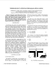
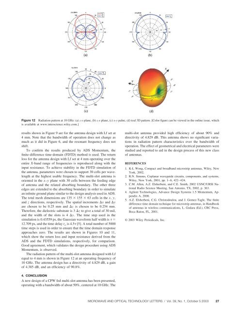
Figure 12 Radiation pattern at 10 GHz: (a) z-y plane, (b) z-x plane, (c) x-y palne, (d) toal 3D pattern. [Color figure can be viewed in the online issue, whichis available at www.interscience.wiley.com.]results shown in Figure 9 are <strong>for</strong> the <strong>antenna</strong> design with Lf set at4 mm. Note that the bandwidth of operation does not change asmuch as it did in Figure 6, and the resonant frequency does notshift.To confirm the results produced by ADS Momentum, thefinite-difference time-domain (FDTD) method is used. The returnloss <strong>for</strong> the <strong>antenna</strong> design with Lf set at 4 mm operating over theentire X-band range of frequencies is reproduced along with theinput resistance. To achieve stability in the FDTD simulation ofthe <strong>antenna</strong>, parameters were chosen to support 30 cells per wavelengthat the highest usable frequency. The <strong>multi</strong>-<strong>slot</strong> <strong>antenna</strong> isoriented in the x–y plane with 30 cells between the feeding edgeof <strong>antenna</strong> and the related absorbing boundary. The other threeedges are extended to the absorbing boundary in order to simulatean infinite ground plane similar to the design analysis used in ADS.The total mesh dimensions are 135 155 63 cells in the x, y,and z directions, respectively. The spatial increments x and yare chosen to be 0.25 mm and z is chosen to be 0.254 mm.There<strong>for</strong>e, the dielectric substrate is 3 z to give a total of 30 mil,and the width of the <strong>slot</strong>s is 4 y. The time step used in thesimulation is 0.43559 ps, the Gaussian wave<strong>for</strong>m half width is 12.709 ps, and the time delay t o is 4.5 [5]. A total number of 5000time steps is used in order to ensure that the time domain responseapproaches zero. The results are shown in Figures 10 and 11,which show the return loss and input resistance derived from theADS and the FDTD simulations, respectively, <strong>for</strong> comparison.Good agreement, which validates the design procedure using ADSMomentum, is observed.The radiation pattern of the <strong>multi</strong>-<strong>slot</strong> <strong>antenna</strong> designed with Lfequal to 4 mm is shown in Figure 12 at an operating frequency of10 GHz. The <strong>antenna</strong> design has a directivity of 4.829 dB, a gainof 4.385 dB, and an efficiency of 90.8%.<strong>multi</strong>-<strong>slot</strong> <strong>antenna</strong> provided high efficiency of about 90% anddirectivity of 4.829 dB. This <strong>antenna</strong> shows no significant variationsin radiation pattern characteristics over the bandwidth ofoperation. The effect of geometrical and electrical parameters werestudied and reported to aid in the design process of this new classof <strong>antenna</strong>s.REFERENCES1. K-L Wong, Compact and broadband microstrip <strong>antenna</strong>s, Wiley, NewYork, 2002.2. R.N. Simons, Coplanar <strong>waveguide</strong> circuits, components, and systems,Wiley, New York, 2001, pp. 1–6, 422–424.3. C.M. Allen, A.Z. Elsherbeni, and C.E. Smith, 2002 USNC/URSI NationalRadio Science Meeting, San Antonio, TX, 2002, p. 363.4. Agilent Technologies, Advance Design Systems 1.5 Momentum, AppendixA, 2000.5. A.Z. Elsherbeni, C.G. Christodoulou, and J. Gomez-Tagle, The finitedifference time domain technique <strong>for</strong> microstrip <strong>antenna</strong>s, in Handbookof <strong>antenna</strong>s in wireless communications, L. Godara (Ed.), CRC Press,Boca Raton, FL, 2001.© 2003 Wiley Periodicals, Inc.4. CONCLUSIONA new design of a CPW <strong>fed</strong> <strong>multi</strong>-<strong>slot</strong> <strong>antenna</strong> has been presented,operating with a bandwidth of about 50%, centered at 10 GHz. TheMICROWAVE AND OPTICAL TECHNOLOGY LETTERS / Vol. 39, No. 1, October 5 2003 27