
Create successful ePaper yourself
Turn your PDF publications into a flip-book with our unique Google optimized e-Paper software.
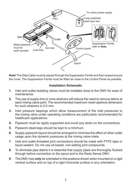
To mains power supplyPSU3 amp switchedfused spur boxDMVOutletMetal pipeworkmust beearth bondedCold inletHot inletControl panelSuppression Ferrite,refer to Note.SpoutNote! The Data Cable must be placed through the Suppression Ferrite and then looped aroundthe cover. The Suppression Ferrite must be fitted as close to the Control Panel as possible.Installation Schematic1. Inlet and outlet isolating valves must be installed close to the DMV for ease ofmaintenance.2. The use of supply-line or zone strainers will reduce the need to remove debris ateach mixing valve point. The recommended maximum mesh aperture dimensionfor such strainers is 0.5 mm.3. Inlet pressure tappings which allow measurement of the inlet pressures tothe mixing valve under operating conditions are particularly recommended forhealthcare applications.4. Pipework must be rigidly supported and avoid any strain on the connections.5. Pipework dead-legs should be kept to a minimum.6. Supply pipework layout should be arranged to minimise the effect of other outletusage upon the dynamic pressures at the mixing valve inlets.7. Inlet and outlet threaded joint connections should be made with PTFE tape orliquid sealant. Do not use oil-based, non-setting joint compounds.8. To eliminate pipe debris it is essential that supply pipes are thoroughly flushedthrough before connection to the spout and to the <strong>Rada</strong> Sense DMV.9. The DMV may only be orientated in the positions shown when mounted on a rigidvertical surface and on top of a rigid horizontal surface in any orientation.7